1
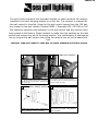
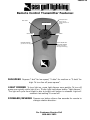
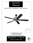
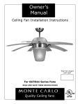
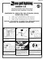
16004-15
16004-15
INSTRUCTIONS FOR YOUR NEW
REMOTE FAN CONTROL SYSTEM
CAUTION: To reduce the risk of electric shock,
install only in Fan
1.
Model CD-52, manufactured by Ja Yang (E106510)
3.
Model AC-552, manufactured by Air Cool (E75795)
2.
Model 9701, manufactured by Furn Fan (E141261)
CAUTION : FOR CONTROL OF SHADE POLE, PERMANENT SPLIT
CAPACITOR, OR UNIVERSAL MOTORS ONLY.
1
2
3
Caution: Turn off power at fuse box to avoid
possible electrical shock.
Top view of switch housing plate.
Disconnect Molex Connectors in switch housing
plate by pushing down on tab and pulling the
two (molex connectors) apart.
4
5
6
Remote Transmitter Dip swtiches
Remote Receiver Dip switches
Connect the molex from the receiver to the
molex in the switch housing plate by aligning
and sliding together. Note: For longer distance
operation, coil receiver antenna around the
natural wire (white wire).
Set dip switches on the Remote Transmitter and
Remote Receiver to the same settings. This
must be done so the units will communcate
properly. If you have other fans you can set to
control from one transmitter by setting both
receivers the same as the transmitter. If you
have more than one fan with remote. You can
set the dip switches to different positiosns to
have seperate control.
Align gap in receiver with the screw between
speed switch and reverse switch and slide
receiver (Dip switch facing housing plate) into
switch housing plate. Receiver should fit directly into area in the switch housing plate. Note:
If installing light kit, use the blue and white
wire from the receiver.
16004-15
The wall control transmits the command signals via radio waves to the receiver
installed in the fan’s hanging bracket or on the fan. The receiver is required for
the wall control to function. Power for the wall control comes from the 12V battery located in the wall remote. Duracell MN21 / Eveready A23 / GP 23A all 12V.
The frequency switches (dip switches) on the wall control and the receiver have
been preset at the factory. Please recheck to make sure the switches on the wall
control and receiver are set to the same position. Any combination of settings are
fine as long as the wall control and ceiling fan receiver are set to the same position.
CAUTION: TURN OFF POWER AT FUSE BOX TO AVOID POSSIBLE ELECTRICAL SHOCK.
1
2
Remove cover by snaping off from top or bottom. Remove battery cover. Install 12V battery
into wall remote. Duracell MN21 / Eveready A23
/ GP 23A all 12V.
3
WALL MOUNT INSTALL
Install wall control unit to outlet box
using machine screws provided.
HAND HELD INSTALL
Place face plate over battery compartment and
buttons. Place remote over 2 pins on front
cover. Attach cover of remote by placing over 4
pins and snaping into place.
4
Attach front cover to wall control
with screws provided. Snap battery
cover in place.
16004-15
Remote Control Transmitter Features:
LED LIGHT
Forward/Reverse
(Press once to
change direction of
the fan.
MEDIUM SPEED
LOW SPEED
HIGH SPEED
FAN OFF SETTING
(Turns fan off only)
LIGHT ON/OFF SETTING AND DIMMER
(Press and hold to
dim light infinitively)
FAN SPEED Depress “l dot” for low speed, “2 dots” for medium or “3 dots” for
high. To turn fan off press square”.
LIGHT DIMMER To turn light on, press light dimmer once quickly. To turn off
press once quickly while light is on. To dim light hold down button “light dimmer”.
The light will cycle from bright to dim to bright until button is released. Light will
maintain last setting if turned off.
FORWARD/REVERSE Depress rev button allow a few seconds for remote to
change rotation direction.
For Customer Service Call
866-449-2821