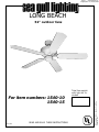
1
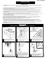
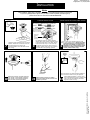
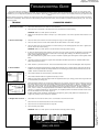
Page 1 – 5V52/5VB52-ULEnglish/Rev. 0/12/08/1997
®
LONG BEACH
52" outdoor fans
HC-340
READ AND SAVE THESE INSTRUCTIONS
© Copyright 1999, Sea Gull Lighting
Products, Inc.
For item numbers: 1540-10
1540-15
Total fan weight
with light kit included.
Page 2 – 5V52/5VB52-ULEnglish/Rev. 0/12/08/1997
INSTALLATION
Safety Tips
WARNING: TO REDUCE THE RISK OF FIRE, ELECTRIC SHOCK, OR INJURY TO PERSONS, OBSERVE THE FOLLOWING:
READ AND SAVE THESE INSTRUCTIONS
1. Installation work and electrical wiring must be done by qualified person(s) in accordance with all applicable codes and standards(ANSI/NFPA 701993), including fire-rated construction.
2. Use this unit only in the manner intended by the manufacurer. If you have any questions contact the manufacturer.
3. After making the wire connections, the wires should be spread apart with the grounded conductor and the equipment-grounding conductor on
one side of the outlet box and ungrounded conductor on the other side of the outlet box.
4. Before you begin installing the fan, Switch power off at Service panel and lock service disconnecting means to prevent power from being
switched on accidentally. When the service disconnecting means cannot be locked, securely fasten a prominent warning device, such as a tag,
to the service panel.
5. Be cautious! read all instructions and safety information before installing your new fan. Review the accompanying assembly diagrams.
6. When cutting or drilling into wall or ceiling, do not damage electrical wiring and other hidden utilities.
7. Make sure the installation site you choose allows the fan blades to rotate without any obstructions. Allow a minimum clearance of 7 feet from the
floor to the trailing edge of the blade.
8. To reduce the risk of fire, electric shock, or personal injury, mount to outlet box or supporting system acceptable for fan support.
(Mounting must support at least 35 lbs.)
9. Do not bend blade holders during installation to motor, balancing or during cleaning. Do not insert foreign object between rotating blades.
10. Attach the mounting bracket using only the hardware supplied with the outlet box.
11. To reduce the risk of fire or electric shock, do not use this fan with any solid state fan speed control device, or variable speed control.
12. If this unit is to be installed over a tub or shower, it must be marked as appropriate for the application.
13. NEVER place a switch where it can be reached from a tub or shower.
14. The combustion airflow needed for safe operation of fuel-burning equipment may be affected by this unit’s operation. Follow the heating
equipment manufacturer’s guideline safety standards such as those published by the National Fire Protection Association (NEPA), and the
American Society for Heating, Refrigeration and Air Conditioning Engineers (ASHRAE) and the local code authorities.
15. Before servicing or cleaning unit, Switch power off at Service panel and lock service disconnecting means to prevent power from being switched
on accidentally. When the service disconnecting means cannot be locked, securely fasten a prominent warning device, such as a tag, to the
service panel.
16. NOTE--FOR OUTDOOR FANS ONLY: Suitable for use in wet locations when installed in a GFCI protected branch circuit.
TOOLS REQUIRED
Phillips Screwdriver
Wire Cutters
Pliers
1
Unpack and inspect fan carefully to be
certain all contents are included. (See
exploded view parts list.)
2
Turn off power at breaker box to avoid
possible electrical shock.
Step Ladder
3
Use outlet box suitable for fan support.
Secure outlet box directly to the building
structure using ceiling joist screws.
Outlet box must support 35 lbs.
Cotter
Pin
Clevis
Pin
YOKE CANOPY
4
Install mounting bracket to outlet box
in ceiling using the screws provided
with the outlet box and washers.
Install downrod into yoke canopy and ceiling
canopy. Feed motor wires through downrod/
canopy assembly. Insert the 3 lead wires
from the fan and the earth wire on the
hanger ball through the downrod cover.
This prevernts water from running
through the downrod.
5
6
Set
Screws
Insert downrod into motor yoke. Next,
insert clevis pin through yoke and
downrod and secure with cotter pin.
(see inset) Tighten both yoke set screws
to further secure downrod.
© Copyright 1999, Sea Gull Lighting
Products, Inc.
1
1
1
Page 3 – 5V52/5VB52-ULEnglish/Rev. 0/12/08/1997
INSTALLATION
Note:
After installation, please refer to operation, maintenance and troubleshooting sections in this manual.
If your fan is packaged with a light kit or if you wish to install a separately purchased light kit,
please refer to the insert sheet titled: LIGHT KIT INSTALLATION
STANDARD WIRING OPTION
Ball
Notch
WIRING OPTION WITH WALL SPEED CONTROL
Light Switch
*ATTACH BLUE WIRE
ONLY IF ATTACHING
LIGHT KIT WITH FAN
Secure with
twist-lock
wire
connectors
(included)
7
Carefully lift fan assembly onto mounting
bracket. Rotate fan so that the notch on
the ball engages the ridge in the
mounting bracket. This will allow handsfree wiring.
8
Fan Switch
*
Ridge
Wall
control
For pullchain controls, follow diagram
above. Make sure that all exposed wiring
is secured inside wire nuts. Note: Wires
from house may vary in color and may
not include ground wire. After wiring is
conplete, gently push wires into junction
box with wire nuts pointing upward.
For control of fan and optional light from wall
location, follow diagram above. NOTE: A professional electrician is recommended for
this type of installation. Ceiling fan is
suitable for use in wet locations when
installed in a GFCI protected branch
circuit (outdoor fans only).
9
Shipping
Stabilizer
Tab
Washers
11
Attach blade brackets to blades
using the blade bracket screws and
washers provided.
12
© Copyright 1999, Sea Gull Lighting
Products, Inc.
10
Raise the canopy up and align the
four holes in the canopy with the
four holes in the hanger bracket.
Secure with screws provided.
Check the motor for plastic shipping stabilizer
tabs, and remove them if they are present.
Attach blade assembly to motor using
the noise-dampening motor gaskets and
motor screws and washers provided.
Tighten screws securely.
Page 4 – 5V52/5VB52-ULEnglish/Rev. 0/12/08/1997
TROUBLESHOOTING GUIDE
If you have difficulty operating your new ceiling fan, it may be the result of incorrect assembly, installation, or wiring. In some cases, these
installation errors may be mistaken for defects. If you experience any faults, please check this Trouble Shooting Chart. If a problem cannot be
remedied, or you are experiencing difficulty in installation, please call our Customer Service Center at the number printed on your parts list insert
sheet.
Warning: Before servicing or cleaning unit, Switch power off at Service panel and lock service disconnecting means to prevent power from being
switched on accidentally. When the service disconnecting means cannot be locked, securely fasten a prominent warning device, such as a tag, to
the service panel.
SUGGESTED REMEDY
TROUBLE
1. If fan does not start:
1.
Check main and branch circuit fuses or circuit breakers.
2.
Check line wire connections to fan and switch wire connections in switch housing.
CAUTION: Make sure main power is turned off.
2. If fan sounds noisy:
3.
Make sure forward/reverse switch is firmly in up or down position. Fan will not operate when switch is in the
middle.
1.
Check to make sure all screws in motor housing are snug (not over tightened).
2.
Check to make sure the screws which attach the fan blade holder to the motor are tight.
3.
Check to make sure wire nut connectors in switch housing are not rattling against each other or against the
interior wall of the switch housing.
CAUTION: Make sure main power is turned off before entering switch housing.
3. If fan wobbles:
Touching
Ceiling
4.
If using an optional Ceiling Fan Light Kit, check to be sure the screws securing the glassware are finger tight.
Check to be sure light bulb is tight in socket and not touching glass shade(s). If vibration persists from
glass, remove glass and install a
1/4" wide rubber band on glass neck to act as an insulator. Replace glass and tighten screws against rubber
band.
5.
Some fan motors are sensitive to signals from Solid State variable speed controls. DO NOT USE a Solid
State variable speed control.
6.
Allow "break-in" period of 24 hours. Most noises associated with a new fan will disappear after this period.
1.
All blades are weighed and grouped by weight. Natural woods vary in density which could cause the fan to
wobble even though all blades are weight-matched. The following procedures should eliminate most of the
wobble. Check for wobble after each step.
2.
Check that all blades are screwed firmly into blade holders.
3.
Check that all blade holders are tightened securely to motor.
4.
Make sure that canopy and mounting bracket are tightened securely to ceiling junction box and junction box
is mounted firmly to ceiling joist.
5.
Most fan wobble problems are caused when blade levels are unequal. Check this level by selecting a point on
the ceiling above the tip of one of the blades. Measure this distance as shown in Figure 1. Keeping measure
within 1/8", rotate the fan until the next blade is positioned for measurement. Repeat for each blade. If all
blade levels are not equal, you can adjust blade levels by the following procedure. To adjust a blade tip
down, insert a washer (not supplied) between the blade and blade holder at the screw closest to the motor
(Figure 2). To adjust a blade tip up, insert washer (not supplied) between the blade and blade holder at the
two screws farthest from the motor (Figure 2).
6.
If blade wobble is still noticeable, interchanging two adjacent (side by side) blades can redistribute the
weight and possibly result in smoother operation.
Figure 1
Fan Blade
Blade Brackets
Blade Tip Up:
Fan Blade
Figure 2
4. If light does not work: 1.
Check blue wire from fan to make sure it is connected to hot wire from house.
2.
Check for loose or disconnected wires in fan switch housing.
3.
Check for loose or disconnected wires in light kit.
4.
Check for faulty light bulbs.
CAUTION: Make sure main power is turned off before entering switch housing.
FOR TECHNICAL SUPPORT CALL:
(866) 449-2821
© Copyright 1999, Sea Gull Lighting
Products, Inc.
Blade Tip Down:
Page 5 – 5V52/5VB52-ULEnglish/Rev. 0/12/08/1997
© Copyright 1999, Sea Gull Lighting
Products, Inc.
3/3/98: REV.0, NEW ISSUE FOR SEA GULL LONGBEACH SERIES 1540 FANS
11/30/2000
Rev. 1, changed step 10 to show side mount screws.