1
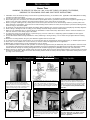
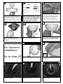
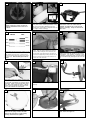
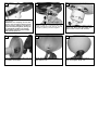
OWNER’S
MANUAL
Ceiling Fan Installation Instructions
QUALITY CEILING FAN
For Quality Pro Series Fans
15160B-255,15161B-191,15162B-15
15163B-191, 15270B-255
Total fan weight
with light kit
READ AND SAVE THESE INSTRUCTIONS
INSTALLATION
SAFETY TIPS
WARNING: TO REDUCE THE RISK OF FIRE, ELECTRIC SHOCK, OR INJURY TO PERSONS,
OBSERVE THE FOLLOWING: READ AND SAVE THESE INSTRUCTIONS
1. Installation work and electrical wiring must be done by qualified person(s) in accordance with applicable codes ANSI/NFPA 70-1999),
including fire-rated construction.
2. Use this unit only in the manner intended by the manufacturer. If you have any questions contact the manufacturer.
3. After making the wire connections, the wires should be spread apart with the grounded conductor and the equipment-grounding conductor on one side of the outlet box and ungrounded conductor on the other side of the outlet box.
4. Before you begin installing the fan, Switch power off at Service panel and lock service disconnecting means to prevent power from
being switched on accidentally. When the service disconnecting means cannot be locked, securely fasten a prominent warning device,
such as a tag, to the service panel.
5. Be cautious! read all instructions and safety information before installing your new fan. Review the accompanying assembly diagrams.
6. When cutting or drilling into wall or ceiling, do not damage electrical wiring and other hidden utilities.
7. Make sure the installation site you choose allows the fan blades to rotate without any obstructions. Allow a minimum clearance of 7
feet from the floor to the trailing edge of the blade.
8. To reduce the risk of fire, electric shock, or personal injury, mount to outlet box or supporting system acceptable for fan support.
(Mounting must support at least 35 lbs.)
9. Do not bend blade holders during installation to motor, balancing or during cleaning. Do not insert foreign object between rotating
blades.
10. Attach the mounting bracket using only the hardware supplied with the outlet box.
11. To reduce the risk of fire or electric shock, do not use this fan with any solid state fan speed control device, or variable speed control.
12. If this unit is to be installed over a tub or shower, it must be marked as appropriate for the application.
13. NEVER place a switch where it can be reached from a tub or shower.
14. The combustion airflow needed for safe operation of fuel-burning equipment may be affected by this unit’s operation. Follow the heating equipment manufacturer’s guideline safety standards such as those published by the National Fire Protection Association (NFPA),
and the American Society for Heating, Refrigeration and Air Conditioning Engineers (ASHRAE) and the local code authorities.
15. Before servicing or cleaning unit, Switch power off at Service panel and lock service disconnecting means to prevent power from being
switched on accidentally. When the service disconnecting means cannot be locked, securely fasten a prominent warning device, such
as a tag, to the service panel.
Phillips Screwdriver
2
1
Before you begin installing the fan, Switch power off
at Service panel and lock service disconnecting
means to prevent power from being switched on
accidentally. When the service disconnecting means
cannot be locked, securely fasten a prominent warning device, such as a tag, to the service panel.
4
Canopy disk
Downrod
TOOLS REQUIRED
Wire Cutters
Pliers
Before installing this fan make sure the outlet box is
properly installed to the house structure. To reduce
the risk of fire, electric shock, or personal injury,
mount to outlet box or supporting system acceptable
for fan support. (Mounting must support at least 35
lbs.)
5
Cross Pin
3
Step Ladder
Use metal outlet box suitable for fan support
(must support 35 lbs). Before attaching fan to
outlet box, ensure the outlet box is securley fastened by at least two points to a structural ceiling
member ( a loose box will cause the fan to wabble). Use only the screws provided with the
outlet box.
6
Yoke
Canopy
Thread leadwires first through the canopy
disk, canopy and lastly downrod.
Keeper
Pin
Insert downrod into yoke on top of the Fan Body.
Align the hole in the Downrod with the hole in the
Yoke. Insert the Pin through the Yoke and Downrod
until the point appears on the other side. Install
the Keeper Pin.
Tighten the 2 Set screws on the Yoke
once the downrod is in place. Check
motor for shipping stabilizers and
remove if present.
7
8
Black
White
Ground
Hang assembled fan from the mounting bracket
installed to ceiling in previous step. Make sure the
fan is hanging straight. Rotate fan until the tab on
the Mounting bracket engages the slot on the
Downrod Ball. This must be done to prevent the fan
body from rotating when the blades are in motion.
10
House
Fan
9
Blue
Black
White
Green
Connect black and blue wire from fan to
Black or (Hot) wire from house. Connect
White wire from Fan to White (Neutral)
wire from house. Connect Ground leads
from mounting bracket and downrod to
Ground lead from house. Refer to
Safety Tips section of manual.
11
Make wire connections to power source using wire
nuts provided. Make sure that no filiments are outside of the wirenut. After making the wire connections, the wires should be spread apart with the
grounded conductor and the equipment-grounding
conductor on one side of the outlet box and
ungrounded conductor on the other side of the outlet
box.
12
Cover
Ring
Make sure the studs protruding from the
bottom of the Mounting bracket are
installed with threads all the way through
the bracket.
For downrod
installation
Go to step 25
Lift Conopy allowing the 2 studs to
protrude through the canopy.
14 Flush Mount Installation
Next lift the cover ring and install knurled
nuts as shown. Tighten the knurled nuts
securely. The canopy should adjust for
any irregularity in the ceiling or Outlet
box.
15
“L” shape
slots
Pass leadwires through the canopy.
Remove side covers from canopy exposing 4 holes. 2 closed holes and 2 open
“L” shape holes.
16
17
18
Remove every other screw as circled
and save for later use.
Install rubber pad between fan
body and canopy.
Place canopy over fan body
aligning holes.
21
20
19
Hands free hook
Replace the 3 screws removed and
tighten securely. Check motor for
shipping stabilizers and remove if
present.
22
Black
White
Ground
House
Fan
Remove the all thread studs from the
lower part of the mounting bracket. Hang
fan from mounting bracket by the
hands free hook into a closed hole on
the edge of the Canopy. .
23
Take 4 screws from hardware pack
and insert 2 one on each side of
bracket to match the L slot screw
holes in canopy. Keep 2 screws for
later use.
24
Blue
Black
White
Green
Connect black and blue wire from fan to Black or (Hot)
wire from house. Connect White wire from Fan to
White (Neutral) wire from house. Connect Ground
leads from mounting bracket and downrod to Ground
lead from house. Refer to Safety Tips section of
manual.
Make wire connections to power source using wire nuts
provided. Make sure that no filiments are outside of
the wirenut. After making the wire connections, the
wires should be spread apart with the grounded conductor and the equipment-grounding conductor on one
side of the outlet box and ungrounded conductor on
the other side of the outlet box.
25
26
Place blade holders onto blades aligning holes
in blade holder with holes in blade. Make sure
that the side of the blade you select is facing
downward. Install 3 screws and fiber washers to back side of blade as shown. Tighten
screws securely. Repeat this process 4 more
times until all blades are assembled.
Install blades to motor using the 10
motor screws provided. Tighten screws
securely.
Lift fan to mounting bracket, aligning the “L”
shape holes with the screws on the mounting bracket. Turn the fan clockwise to lock
in position. Install the other 2 screws included in hardware bag and tighten all 4 securely.
27
Remove nut and save for next step.
28
29
30
Remove switch cap housing from fan.
Remove the plug of fitter. Install
switch cap housing to light kit by
turning clockwise to tighten.
Install keeper nut over lead wires.
Tighten keeper nut onto threaded
pipe from the light kit.
31
32
33
Locate blue and white wire from the fan
marked “For light kit”. Connect blue from fan
to black from light and white from fan to white
from light by pushing connectors together.
Remove 3 screws and washers from
switch cap. Place the light fitter and
tighten with screws and washers.
34
35
36
Remove finial nut, finial cap, hex nut,
and washer from fitter.
Install rubber washer and nut to
glass tighten nut.
Install finial cap and finial nut to
glass and tighten finial nut.
Install 3 x 40 watt Candelabra base bulbs.
Bulbs included.
WARNING: Over lamping the fan will
result in the fan lights shutting down
until the proper wattage of bulbs are
installed. Reset the lights by turning off
the wall switch, breaker,or by remote.
Replace bulbs with the correct wattage
bulbs, turn the power on.
TROUBLE SHOOTING
If you have difficulty operating your new ceiling fan, it may be the result of incorrect assembly, installation, or wiring. In
some cases, these installation errors may be mistaken for defects. If you experience any faults, please check this Trouble
Shooting Chart. If a problem cannot be remedied, or you are experiencing difficulty in installation, please call our
Customer Service Center at the number printed on your parts list insert sheet.
Warning: Before servicing or cleaning unit, Switch power off at Service panel and lock service disconnecting
means to prevent power from being switched on accidentally. When the service disconnecting means cannot
be locked, securely fasten a prominent warning device, such as a tag, to the service panel.
1. If fan does not start:
2. If fan sounds noisy:
1.Check main and branch circuit fuses or circuit breakers.
2.Check line wire connections to fan and switch wire connections in switch housing.
CAUTION: Make sure main power is turned off.
3.Make sure forward/reverse switch is firmly in up or down position. Fan will not operate
when switch is in the middle.
4.Make sure that shipping stabilizer tabs have been removed from motor (see installation
step #13).
1.Check
2.Check
3.Check
other or
to make sure all screws in motor housing are snug (not over tightened).
to make sure the screws which attach the fan blade holder to the motor are tight.
to make sure wire nut connectors in switch housing are not rattling against each
against the interior wall of the switch housing.
CAUTION: Make sure main power is turned off before entering switch housing.
4.If using an optional Ceiling Fan Light Kit, check to be sure the screws securing the glassware are finger tight. Check to be sure light bulb is tight in socket and not touching glass
shade(s). If vibration persists from glass, remove glass and install a 1/4" wide rubber band
on glass neck to act as an insulator. Replace glass and tighten screws against rubber band.
5.Some fan motors are sensitive to signals from Solid State variable speed controls. DO
NOT USE a Solid State variable speed control.
6.Allow "break-in" period of 24 hours. Most noises associated with a new fan will disappear
after this period.
3. If fan wobbles:
4. If light does not work:
1.Make sure that the ridge of the canopy engages the notch in the downrod ball. (See illustration in Step #6 of Downrod Mount installation).
2.Check that all blades are screwed firmly into blade holders.
3.Check that all blade holders are tightened securely to motor.
4.Make sure that canopy and mounting bracket are tightened securely to ceiling junction box
and junction box is mounted firmly to ceiling joist.
5.Most fan wobble problems are caused when blade levels are unequal. Check this level by
selecting a point on the ceiling above the tip of one of the blades. Measure this distance
from blade tip to ceilng. Keeping measure within 1/8", rotate the fan until the next blade is
positioned for measurement. Repeat for each blade. If all blade levels are not equal, you can
adjust blade levels by the following procedure. To adjust a blade tip down, insert a washer
(not supplied) between the blade and blade holder at the screw closest to the motor. To
adjust a blade tip up, insert washer (not supplied) between the blade and blade holder at
the two screws farthest from the motor. Reverse the position of the washer if blades mount
from top of blade.
6.If blade wobble is still noticeable, interchanging two adjacent (side by side) blades can
redistribute the weight and possibly result in smoother operation.
1.Check blue wire from fan to make sure it is connected to hot wire from house
2.Check for loose or disconnected wires in fan switch housing.
3.Check for loose or disconnected wires in light kit.
4.Check for faulty light bulbs.
CAUTION: Make sure main power is turned off before entering switch housing.
WARNING: Over lamping the fan will result in the fan lights shutting down
until the proper wattage of bulbs are installed.
Reset the lights by turning off the wall switch, breaker,or by remote. Replace bulbs with
the correct wattage bulbs, turn the power on.
Customer Service Center:
301 West Washington St.
Riverside, NJ 08075
1-800-519-4092