Transcript
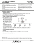
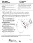
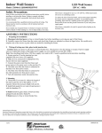
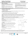
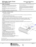
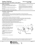
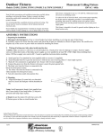
HD Supply Outdoor Wall Pack
Fluorescent Wall Sconce
Model: 326912 & 326930 (TPDW70050LBK/TPDW110050LBK)
120VAC / 60Hz
Safety Precautions
Read all safety precautions and installation instructions carefully
before installing or servicing this fixture. Failure to comply with these
instructions could result in potentially fatal electric shock and/or
property damage.
It is recommended that a qualified electrician perform all wiring. This
fixture must be wired in accordance with all national and local
electrical codes.
Do not handle any energized fixture or attempt to energize any fixture
with wet hands or while standing on a wet or damp surface or in water.
This fixture is designed for use in a 110-120VAC, 60Hz fused circuit.
Do not use on a dimming circuit.
To reduce the risk of electrical shock, and to assure proper operation,
this fixture must be adequately grounded. To accomplish proper
grounding, there must be a separate ground wire (green) contact
between this fixture and the ground connection of your main power
supply panel.
This fixture is intended to be used for general outdoor lighting in wet
locations.
ASSEMBLY INSTRUCTIONS
1. Preparing for installation
A. Disconnect electrical power at fuse or circuit breaker box before installing or servicing any part of this fixture.
B. Carefully remove the fixture from the carton.
2.
Wiring-all wiring must take place inside junction box (not included)
Caution: Make sure power is off at fuse or circuit breaker box. Check power wires for damage or scrapes. If power supply
wires are within three inches of the ballast power supply, use wire suitable for at least 90C (194F). Note: Most dwellings built
before 1985 have supply wire rated to 60C. Consult a qualified electrician before installing.
A. Secure fixture arm (2) on the threaded cover (3) (not supplied) with locknut (4) (supplied).
B. Make all wire connections to appropriate wire. Secure with wire nuts (included).
C. Connect the green wire from the fixture to the power source green wire.
D. The black wire from the fixture is connected to the
black wire from power source.
E. The white wire from the fixture is connected to the
white (neutral) wire from power source.
F. Tuck all connections neatly into junction box.
G. Secure threaded cover (3) on the junction box with
two screws (not supplied).
5. Positioning Fixture with the Swivel/Arm Assembly
A. Loosen the thumb nut on the swivel arm assembly
base. Adjust the correct fixture aiming angle position by
rotating it upward or downward.
6. Restore power at fuse or circuit breaker box.
Limited Factory Warranty
American Fluorescent Corporation warrants this fixture is free from defects in materials and workmanship when installed and used under normal
operating conditions for a period of 2 years from date of purchase. This warranty covers all component parts and extends only to replacement of
defective fixture or components; it does not cover failure due to improper installation, misuse, mishandling or damage incurred in transit
1 of 1
8060665 R0