1
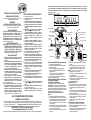
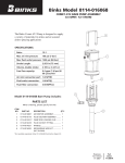
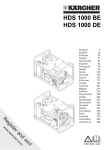
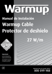
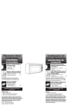
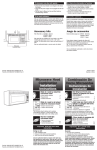
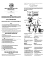
Tools Needed: Slotted screwdriver, Adjustable wrench, Electrical Hand drill, Step ladder, Wire cutters, Wiring supplies as
required by electrical code.
ELECTRICAL CONNECTIONS (for all models)
Required Supply Circuit: 120V, 60Hz
LINE VOLTAGE FLEXIBLE TRACK SYSTEM
INSTRUCTION MANUAL
Please read carefully and save these instructions, as you may need them at a later date.
Connect the white wire(s) from the fixture to the white wire of the supply circuit. Connect the black wire(s) from the fixture to the
black wire of the supply circuit. Connect the green or bare copper wire to the ground wire of the supply circuit. Use UL/CSA
listed wire connectors suitable for the size type, and number of conductors. No loose strands or loose wires should be present.
Secure wire connectors with UL/CSA listed electrical tape.
HOW TO INSTALL:
SAFETY
WARNING: RISK OF ELECTRIC SHOCK
Disconnect the electrical supply circuit before installing light fixture.
GENERAL
All electrical connections must be in accordance with local codes, ordinances or national electrical codes. If you are unfamiliar
with methods of installing electrical wiring, secure the services of a qualified electrician. Before starting installation, disconnect
the power by turning off the circuit breaker or removing the fuse at the fuse box.
INSTALLATION INSTRUCTIONS
CAUTION: MAKE SURE POWER IS TURNED OFF AT THE ELECTRICAL PANEL BOX BEFORE BEGINNING YOUR
INSTALLATION. TURNING POWER OFF AT WALL SWITCH IS NOT SUFFICIENT TO PREVENT ELECTRICAL SHOCK.
Outlet box
Anchor
Wire connector
Stanchion Ceiling screw
Canopy mounting bracket
Mounting bracket screw
Outlet Box Canopy Screw
Power Canopy
Stanchion
Support stem
End cap
Track Mounting Bracket
GENERAL
1. Be sure to read these installation instructions and review the diagrams thoroughly before installing the light fixture.
2. All electrical connections must be in accordance with local codes and the National Electrical Code. If you are unfamiliar
with methods of installing electrical wiring, secure the services of a qualified licensed electrician.
3. These fixtures are intended to be mounted to a 4 square x 2 1/8 deep metal octagon outlet box. The box must be
directly supported by the building structure.
4. Before starting the installation, disconnect the power by turning off the circuit breaker or by removing the appropriate fuse
at the fuse box. Turning the power off using the light switch is not sufficient to prevent electrical shock.
Note: The important safeguards and instructions appearing in this manual are not meant to cover all possible conditions and
situations that may occur. It must be understood that common sense, caution and care are factors that cannot be built into
any product. These factors must be supplied by the person(s) caring for, installing and operating the fixture.
IMPORTANT SAFETY INSTRUCTIONS
1. Read all instructions.
2. Do not install this lighting system in a damp or wet location.
3. Before energizing make sure that the lighting system is clear of all material which could cause a direct short and check all
electrical connections to make sure they are tight.
4. CAUTION Hot surface, keep away from curtains and other combustible materials.
5. Lighted lamp is hot! Do not touch lamp at any time. Use a soft cloth or relamping tools (see diagram), Oil from skin may
damage lamp. Turn off power and allow bulbs to cool before replacing.
6. Lamp gets hot quickly! Contact only switch or plug when turning on. Do not touch hot lamp lens.
7. Do not conceal or extend bus-bar conductors through a building wall.
8. Do not install any part of this system (TRACK) less than 7 feet (2.2m) above floor.
9. To reduce the risk of fire and burns, do not install this lighting system where non insulated open bus-bar conductors can be
shorted or contact any conductive metals.
10. To reduce the risk of fire and overheating, make sure all connections are tight.
11. Do not install any lamps closer than 6 inches (15.25cm) from any curtain or similar combustible material.
12. Turn off electrical power before modifying the light system in anyway.
13. Use minimum 20 spacing between stanchions when using 7 stanchions.
14. For use with EC series line voltage flexible track system only. Do not cut any track sections.
15. CAUTION To reduce the risk of a burn during relamping, remove from the track before relamping.
16. This track system is to be supplied by a single branch 120 volt circuit.
17. Disconnect electrical power before adding to or changing the configuration of the track.
READ AND SAVE THESE INSTRUCTIONS
UNPACK THE FIXTURE
Parts List: Check the contents to be sure everything is included, 12' flexible track , one power canopy, one canopy mounting
bracket, 7 stanchions, 7 support stems, 7 track mounting brackets, and two track end caps.
Retaining cap
Power Connector
16mm
Power Connector cover
Method 2
track
Retaining cap
Fixture(Sold Separately)
Fixture Adapter
INSTALL THE CANOPY (AS SHOWN IN DIAGRAM)
1. Turn off the main power.
2. Install mounting bracket to existing outlet box with
screws.
3. Pull wires through mounting bracket.
A. Make ELECTRICAL CONNECTIONS as directed
above.
B. Carefully tuck connected wires back into the outlet
box.
4. Secure Outlet Box Canopy to the mounting bracket with
the screws provided.
INSTALL THE LINE VOLTAGE FLEXIBLE TRACK (AS
SHOWN IN DIAGRAM)
CREATE LAYOUT
The line voltage flexible track kit allows you maximum
flexibility in creating an attractive lighting system for your
room. The 12 track can be mounted in an infinite
combination of curves and straight runs. The adjustable track
heads can be mounted anywhere along the track run.
INSTALL CEILING SUPPORTS
Method 1:
1. Remove support stems from stanchions.
2. Lay out your track design and mark the position for each
stanchion. Evenly space stanchions so that they form
desired pattern. (Use minimum 20 spacing between
stanchions when using 7 stanchions.)
3. Drill holes in the ceiling at desired stanchion location by
electrical drill. (Note: Please use diameter 6mm drill bit)
4. Install enclosed screw anchors into drilled holes.
Decorative ring
Stanchion
5. Insert the stanchion screws to secure stanchions to the
ceiling.
6. Screw the support stems into the stanchions , and then
install the track mounting brackets to the support stems
as shown in the figure.
Method 2: (As shown in diagram)
1. Repeat step 1,2 of method 1.
2. Drill 5/8 inches (16mm) holes in the ceiling at desired
stanchion location.
3. Push toggle bolts into the holes drilled into the ceiling
and tighten toggle bolts until the stanchion and
decorative ring secured.
4. Repeat step 6 of method1.
INSTALL TRACK
1. Remove the retaining cap on the power connector.
2. Open the power connector cover and align the two slots
of the track to the two tabs on the power connector.
3. Close the power connector cover and replace the
retaining cap making sure that the connection is secure.
4. Remove the retaining cap, open the track mounting
bracket, and then insert the flexible track into the track
mounting bracket.
5. Replace the retaining caps to secure the flexible track.
INSTALL FIXTURE(sold separately)
1. Remove the retaining caps from the fixtures.
2. Align the two tabs of the track fixture adaptor to the two
slots on the flexible track.
3. Close the fixture adapters and replace the retaining caps
making sure that the connection is secure
accesorio al cable negro del circuito de alimentacion. Conecte el conductor verde o de cobre desnudo al cable de tierra del
circuito de alimentacion. Use capuchones de empalme certificados por UL/CSA, adecuados para el tamano, tipo y cantidad de
conductores. No deben quedar conductores o cables sueltos. Asegure los capuchones de empalme con cinta aisladora
certificada por UL/CSA.
SISTEMAS DE RIEL FLEXIBLE DE TENSION DE
LINEA MANUAL DE INSTRUCCIONES
Lea cuidadosamente y guarde estas instrucciones, porque
puede necesitarlas mas adelante.
SEGURIDAD
ADVERTENCIA: RIESGO DE DESCARGA ELECTRICA
Antes de instalar el accesorio de iluminacion, desconecte el
circuito de la red de suministro electrico.
INDICACIONES GENERALES
Efectue todas las conexiones electricas de acuerdo con las
reglamentaciones municipales y nacionales vigentes. Si
usted no esta familiarizado con los metodos de instalacion
del cableado electrico, contrate los servicios de un perito
electricista habilitado. Antes de iniciar la instalacion, corte la
alimentacion electrica general con el interruptor principal o
quitando los fusibles de entrada.
INSTRUCCIONES DE INSTALACION
PRECAUCION: ANTES DE COMENZAR LA INSTALACION,
ASEGURESE DE QUE EL SUMINISTRO ELECTRICO
ESTE DESCONECTADO EN LA CAJA DEL CIRCUITO
ELECTRICO. DESCONECTAR LA ENERGIA EN EL
INTERRUPTOR DE PARED NO ES SUFICIENTE
PARA EVITAR DESCARGAS ELECTRICAS.
INDICACIONES GENERALES
1. Asegurese de leer estas instrucciones y revisar los
diagramas con cuidado antes de instalar el accesorio de
iluminacion.
2. Todas las instalaciones electricas deben observar los
codigos locales y el Codigo de Electricidad Nacional de
EE.UU. Si usted no esta familiarizado con los metodos
de instalacion del cableado electrico, contrate los
servicios de un perito electricista habilitado.
3. Estos artefactos estan previstos para usar con una caja
de empalmes octogonal metalica de 4 x 2 1/8 pulg. (100
x 54 mm) de profundidad. La caja debe ser soportada
directamente por la estructura del edificio.
4. Antes de empezar con la instalacion, desconecte la
alimentacion electrica con el interruptor general o los
fusibles de entrada. Cortar la alimentacion al circuito
solamente con la llave de luz, no es suficiente para
prevenir una electrocucion.
Nota: Las importantes recomendaciones e instrucciones
proporcionadas en este manual no abarcan todas las
condiciones y/o situaciones posibles que pudieran
presentarse. Se sobreentiende que el sentido comun, la
precaucion y la atencion al trabajo no son parte de
ningun producto. Son factores que debe tener en cuenta
quien ejecute la instalacion, cuide y opere el accesorio.
INSTRUCCIONES DE SEGURIDAD IMPORTANTES
1. Lea todas las instrucciones.
2. No instale este sistema de iluminacion en lugares
humedos o mojados.
3. Antes de conectar la alimentacion, asegurese de que el
sistema de iluminacion este libre de materiales que
puedan causar un cortocircuito directo y verifique todas
las conexiones electricas para asegurarse de que esten
apretadas.
4. PRECAUCION
Superficie caliente, mantengala
alejada de cortinas y otros materiales combustibles.
5. !La bombilla encendida esta caliente! No toque la
bombilla en ningun momento. Use un trapo blando o
herramientas especiales (como se ilustra en el
diagrama). La grasitud de la piel puede danar la
bombilla.
6. !La bombilla se calienta rapidamente! Toque solo el
interruptor o el enchufe al encenderla. No toque el
cristal de la bombilla caliente.
7. No esconda ni extienda los conductores de la barra de
distribucion a traves de una pared de construccion.
Desconecte la energia electrica y deje que se enfrie
antes de reemplazar la bombilla.
8. No instale ninguna parte de este sistema (RIEL) a
menos de 7 pies (2.2 m) sobre el nivel del piso.
9. Para reducir el riesgo de incendio y quemaduras, no
instale este sistema de iluminacion alli donde puedan
producirse cortocircuitos de los conductores de la barra
de distribucion abierta sin aislar o donde estos puedan
hacer contacto con materiales conductores.
10. Para reducir el riesgo de incendio o recalentamiento,
asegurese de que todas las conexiones esten apretadas.
11. No instale ninguna bombilla a una distancia menor de 6
pulgadas (15 cm) de cualquier cortina o material
combustible similar.
12. Desconecte la alimentacion electrica antes de modificar
de cualquier manera el sistema de iluminacion.
13. Use una separacion minima de 20 pulgadas (50 cm)
entre anclajes cuando utilice 7 anclajes.
14. Solo para instalacion con sistemas de riel flexible de
tension de linea serie EC. No corte ninguna seccion del
riel.
15. PRECAUCION Para reducir el riesgo de quemaduras
durante el cambio de bombillas, retirelo del riel antes del
cambio.
16. Este sistema de riel debe ser alimentado por un circuito
de 120 voltios de un solo ramal.
17. Desconecte la energia electrica antes de hacer
agregados a la configuracion del riel o de cambiarla.
LEA Y CONSERVE ESTAS INSTRUCCIONES
DESEMBALAJE DEL PRODUCTO
Lista de piezas: Verifique el contenido para asegurarse de que esten todos los elementos, riel flexible de 12 pies (3.6 m), un
roseton de alimentacion, un soporte de montaje del roseton, 7 anclajes, 7 vastagos de soporte, 7 soportes de montaje del riel
y dos capuchones de extremo del riel.
Herramientas necesarias: Destornillador Phillips, llave ajustable, Perforadora
electrica de mano,escalera, pinza para cortar cables, elementos de cableado requeridos por el codigo de electricidad.
CONEXIONES ELECTRICAS (para todos los modelos)
Circuito de alimentacion requerido: 120 V, 60 Hz
Conecte el o los cables blancos del accesorio al cable blanco del circuito de alimentacion. Conecte el o los cables negros del
OMO INSTALAR EL ACCESORIO:
Caja de empalme
Capuchon de empalme
Anclaje
Tornillo del soporte
de montaje
Tornillo del roseton de la
caja de empalme
Soporte de montaje del roseton
Tornillo de anclaje del cielo raso
Roseton de alimentacion
Soporte del anclaje
Vastago de soporte
tapa para
extremo
Soporte de montaje del riel
Conector de alimentacion
Tapa de retencion
Cubierta del conector
de alimentacion
16mm
perno
acodillado
riel
Metodo 2
Tapa de retencion
accesorio (vendidos
por separado)
Adaptador del accesorio
INSTALACION DEL ROSETON (SEGUN EL DIAGRAMA)
1. Desconecte la alimentacion principal.
2. Instale el soporte de montaje en la caja de empalme
existente con tornillos.
3. Pase los cables a traves del soporte de montaje.
A. Haga las CONEXIONES ELECTRICAS como se
explica mas arriba.
B. Vuelva a colocar con cuidado todos los cables
conectados adentro de la caja de empalme.
4. Fije el roseton de la caja de empalme al soporte de
montaje con los tornillos provistos.
INSTALACION DEL RIEL FLEXIBLE PARA TENSION DE
LINEA (SEGUN EL DIAGRAMA)
COMO CREAR LA CONFIGURACION
El riel flexible para tension de linea le brinda maxima
flexibilidad para crear un sistema de iluminacion atractivo
para su habitacion. El sistema de riel de 12 ¦ 3.6 m) puede
ser instalado en una combinacion infinita de tramos curvos y
rectos. Los cabezales del riel ajustable pueden instalarse en
cualquier parte a lo largo del tramo del riel..
INSTALACION DE LOS SOPORTES DE TECHO
Metodo 1:
1. Desmonte los vastagos de soporte de los anclajes.
2. Coloque su diseno de riel y marque la posicion de cada
anclaje. Espacie en forma regular los anclajes de modo
que formen el modelo deseado. (Use una separacion
minima de 20 pulgadas (50 cm) entre anclajes cuando
utilice 7 anclajes. ).
3. Perfore orificios en la posicion deseada de los anclajes
en el cielo raso con la perforadora electrica. (Nota: Use
una broca de 6 mm de diametro.)
4. Instale los tornillos de anclaje incluidos en los orificios
perforados.
anillo decorativo
Soporte del anclaje
5. Inserte los tornillos de anclaje para fijar los anclajes al
cielo raso.
6. Enrosque los vastagos de soporte en los anclajes y
luego instale los soportes de montaje del riel en los
vastagos de soporte como se muestra en la figura.
Metodo 2: (Tal y como aparece en el diagrama)
1. Repita los pasos 1 y 2 del metodo 1.
2. Taladre agujeros de 5/8 de pulgada (16mm) en el techo
en el puntal deseado.
3. Empuje los tornillos articulados en los agujeros
taladrados en el techo y aprietelos hasta que el puntal y
el anillo decorativo esten seguros.
4. Repita el paso 6 del metodo 1.
INSTALACION DEL RIEL
1. Retire la tapa de retencion del conector de alimentacion.
2. Abra la cubierta del conector de alimentacion y alinee
las dos ranuras del riel con las dos lenguetas del
conector.
3. Cierre la cubierta del conector de alimentacion y vuelva
a colocar la tapa de retencion, asegurandose de que la
conexion quede bien firme.
4. Retire la tapa de retencion, abra el soporte de montaje
del riel e inserte luego el riel flexible en el soporte de
montaje del mismo.
5. Vuelva a colocar las tapas de retencion hasta que
quede sujeto.
INSTALACION DEL ACCESORIO (sold separately)
1. Retire las tapas de retencion de los accesorios.
2. Alinee las dos lenguetas del accesorio del riel con las
dos ranuras del riel flexible.
3. Cierre los adaptadores del accesorio y vuelva a colocar
las tapas de retencion, asegurandose de que la
conexion quede bien firm.