1
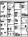
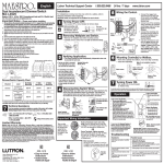
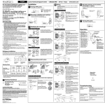
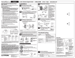
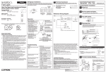
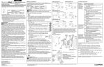
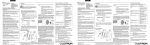
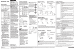
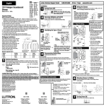
English
®
Fan Speed
Control
P/N 033-102
Multigang Installations
When installing more than one control in the same wallbox, it may be necessary to remove all inner
side sections prior to wiring (see below). Using pliers, bend side sections up and down until they
break off. Repeat for each side section to be removed. Note: Product does not require derating
when side sections are removed.
?
Technical Assistance
If you have questions concerning the installation or operation of this product, call the
Lutron Technical Support Center. Please provide exact model number when calling.
U.S.A. and Canada (24 hrs/7 days):
+1-800-523-9466
Other countries 8am – 8pm ET:
+1-610-282-3800
Do not remove
outside
sections.
Fax +1-610-282-6311
http://www.lutron.com
Lutron Technical Support Center
1-800-523-9466 24 hrs / 7 days
Canopy Module Installation
1
CM-FQ1:
Breaking Side
Sections
120 V~ 60 Hz
1.0 A fan
2
Inside sections are
removed from each
control
Side sections are
removed from both
sides of middle control
Wall Control
MA-FQ4M:
Set fan speed.
• Set fan(s) to highest speed using pull chains.
Reference Wiring Diagram
3
Neutral
120 V~ 60 Hz
4.0 A (up to 4 CM-FQ1)
Install fan(s).
• Install fan(s) according to manufacturer's instructions and check for proper operation.
Quiet Fan Speed Control Multi-Location
System
Canopy Module
www.lutron.com
Turn OFF power.
• Turn power OFF at circuit breaker (or remove fuse).
Accessory Control
MA-AFQ4:
Yellow (Fan)
Tap Button
120 V~ 60 Hz
4.0 A
Warning: For use with one to four ceiling paddle fans only. Do not use with an
exhaust fan.
• Tap once when fan is off - Fan
speed increases to preset level.
• Tap once when fan is on - Fan
speed slows to off.
• Tap twice quickly - Fan speed
increases to full speed.
Live
Press to increase fan speed
Press to decrease fan speed
120 V~
60 Hz
Switched Live
ON
Up to 3
Additional
Fans / Canopy
Modules
(up to 4 total)
ON
Canopy
Module
ON
Operation
OFF OFF OFF
White
Black
Note: Up to four ceiling fans can be controlled on one circuit.
Follow steps 4–7 for each fan.
First Fan / Canopy Module
4
Wall
Control
Disconnect fan.
• Remove canopy enclosure from ceiling fan mounting bracket.
• Leave any green ground wires connected as directed in fan manufacturer's instructions.
• Disconnect fan from remaining wiring in the ceiling.
Brass
LEDs
Brass
Indicate exact fan speed
LEDs will change with each press
One to four ceiling fans only
No exhaust fans
Green
Typical Wire Colors
Black
FASSTM - Front
Accessible
Service Switch
(LEDs not available on Accessory Controls)
Fan
Neutral
Ground
Black
White
Wallbox
See Step 12 for two- and three-location control wiring.
To junction box
To junction box
Important Notes
Mounting
bracket
Please read before installing.
1.
2.
3.
4.
5.
6.
7.
8.
9.
10.
11.
12.
13.
14.
15.
16.
17.
Caution: To avoid overheating and possible damage to other equipment, do not use to control
receptacles, lighting fixtures, transformer-supplied appliances, solid state fan motors, or
exhaust fans. For exhaust fans use Lutron fully variable fan speed controls.
Install in accordance with all national and local electrical codes.
When no “grounding means” exist within the wallbox then the NEC® 2002, Article 404-9 allows
a wall control without a grounding connection to be installed as a replacement, as long as a
plastic, noncombustible wallplate is used. For this type of installation, cap or remove the green
ground wire on the wall control and use an appropriate wallplate such as Lutron’s Claro® or
Satin ColorsTM series wallplates.
The Maestro® fan speed control system consists of a Wall Control, one to four Canopy
Modules, and up to two Accessory Controls. All must be installed correctly before attempting
to control the fans. Do not attempt to mix Lutron controls with those from other manufacturers,
or mix Lutron controls not labeled for use together.
This system is not compatible with fans having a control system built into the motor.
Do not paint Wall Control, Canopy Module, or Accessory Control.
Maestro Controls are not compatible with standard 3-way/4-way switches.
Accessory Controls (MA-AFQ4) cannot be used individually and must be used in conjunction
with a Maestro Wall Control (MA-FQ4M) in a 3-way/4-way application.
In any 3-way/4-way circuit use only one Wall Control (MA-FQ4M) with up to 2 Accessory
Controls (MA-AFQ4).
Operate between 32 °F (0 °C) and 104 °F (40 °C) room temperature. For indoor use only.
Wall Control and Accessory Controls may feel warm to the touch during normal operation.
Recommended wallbox depth is 2.5" (64 mm) minimum.
Clean controls with a soft damp cloth only. Do not use any chemical cleaners.
This system cannot be used to change the direction of the fan. To change the fan direction,
stop the fan, and then change the position of the switch located on the body of the fan.
Do not use pull chains to operate fan(s) after installing this system.
Each Canopy Module must be installed within a fan canopy enclosure.
This device complies with Part 15 of the FCC Rules. Operation is subject to the following two
conditions: (1) this device may not cause harmful interference, and (2) this device must accept
any interference received, including interference that may cause undesired operation.
Canopy
enclosure
Down Rod Bracket
Troubleshooting
Symptom
Possible Cause
Fan does not turn ON or no LEDs turn ON.
• Front Accessible Service Switch (FASS) on
control is pulled out to the OFF position.
• Manual switch on fan is off (ex: pull chain).
• Breaker is OFF or tripped (or fuse blown).
• Fan direction switch is between forward and
reverse.
• Wiring error, call Lutron Technical Support
Center at +1-800-523-9466.
• Unit is not activated properly. Activate system
as described in Step 15.
• Wiring error, call Lutron Technical Support
Center at +1-800-523-9466.
• Communication error. Check wiring; if error
continues, call Lutron Technical Support
Center at +1-800-523-9466.
• Fan blades not properly balanced. See fan
manufacturer's instructions.
• Fan pull chain not set to high.
• Fan pull chain not set to high.
• Wiring error, call Lutron Technical Support
Center at +1-800-523-9466.
LEDs on Wall Control cycle rapidly and
bottom LED is ON.
LEDs on Wall Control cycle rapidly and
second lowest LED is ON.
Fan vibrates or wobbles.
Fan speeds too slow.
Wall Control LEDs respond as expected but
fan does not respond properly.
NOTE: This equipment has been tested and found to comply with the limits for a Class B digital
device, pursuant to Part 15 of the FCC Rules. These limits are designed to provide reasonable
protection against harmful interference in a residential installation. This equipment generates, uses
and can radiate radio frequency energy and, if not installed and used in accordance with the
instructions, may cause harmful interference to radio communications. However, there is no
guarantee that interference will not occur in a particular installation. If this equipment does cause
harmful interference to radio or television reception, which can be determined by turning the
equipment off and on, the user is encouraged to try to correct the interference by one or more of
the following measures:
- Reorient or relocate the receiving antenna.
- Increase the separation between the equipment and receiver.
- Connect the equipment into an outlet on a circuit different from that to which the receiver is
connected.
- Consult the dealer or an experienced radio/TV technician for help.
Important Wiring Information
When making wire connections, follow the recommended strip lengths and combinations for the supplied wire
connectors (see wire connector bag). Note: All wire connectors provided are suitable for copper wire only. For
aluminum wire, consult an electrician.
Wire Connectors:
Use to join 14 AWG or 12 AWG ground wire to 18 AWG Wall Control
ground wire, and to join 18 AWG Canopy Module wire to 12, 14, 16
or 18 AWG wire.
5
Limited Warranty
Flush Mount Bracket
Twist wire
connector
tight.
Connect Canopy Module(s).
• If you have questions about wiring, call the Lutron Technical Support Center at +1-800-523-9466.
(Valid only in U.S.A., Canada, Puerto Rico, and the Caribbean.)
Lutron will, at its option, repair or replace any unit that is defective in materials or manufacture within one year after purchase. For
warranty service, return unit to place of purchase or mail to Lutron at 7200 Suter Rd., Coopersburg, PA 18036-1299, postage prepaid.
THIS WARRANTY IS IN LIEU OF ALL OTHER EXPRESS WARRANTIES, AND THE IMPLIED WARRANTY OF
MERCHANTABILITY IS LIMITED TO ONE YEAR FROM PURCHASE. THIS WARRANTY DOES NOT COVER THE COST OF
INSTALLATION, REMOVAL OR REINSTALLATION, OR DAMAGE RESULTING FROM MISUSE, ABUSE, OR DAMAGE FROM
IMPROPER WIRING OR INSTALLATION. THIS WARRANTY DOES NOT COVER INCIDENTAL OR CONSEQUENTIAL
DAMAGES. LUTRON’S LIABILITY ON ANY CLAIM FOR DAMAGES ARISING OUT OF OR IN CONNECTION WITH THE
MANUFACTURE, SALE, INSTALLATION, DELIVERY, OR USE OF THE UNIT SHALL NEVER EXCEED THE PURCHASE PRICE
OF THE UNIT.
This warranty gives you specific legal rights, and you may have other rights which vary from state to state. Some states do not allow
the exclusion or limitation of incidental or consequential damages, or limitation on how long an implied warranty may last, so the
above limitations may not apply to you.
These products may be covered under the following U.S. patents: 4,992,709; D353,798; and corresponding foreign patents. U.S. and
foreign patents pending. Lutron, Claro, and Maestro are registered trademarks and FASS and Satin Colors are trademarks of Lutron
Electronics Co., Inc. NEC is a registered trademark of the National Fire Protection Association, Quincy, Massachusetts.
© 2006 Lutron Electronics Co., Inc.
Lutron Electronics Co., Inc.
7200 Suter Road
Coopersburg, PA 18036-1299, U.S.A.
Made and printed in the U.S.A. 3/06 P/N 033-102 Rev. A
Wiring the Canopy Module (CM-FQ1):
Use wire connectors to join wires as indicated below
and in the wiring diagram, and to cap any unused
wires.
To junction box
Neutral
Switched
Live
Black
Switched
Live to
additional
fans
Canopy
Module
Canopy
Module Wire:
Connects to:
White
Neutral wires in the junction
box and to fan
Switched Live wire(s) from
Wall Control and to
additional fan(s)
Fan
White
Black
Fan
Yellow
Yellow
To fixture
Lutron Technical Support Center
6
1-800-523-9466
24 hrs / 7 days
www.lutron.com
Control Installation
8 Remove original wallplate and switch.
Insert Canopy Module.
6a - Down Rod Bracket
• Remove the wallplate and switch mounting screws.
• Carefully remove switches from wall (do not remove wires).
• Do not install Canopy Module in ceiling.
• Slide Canopy Module into the ceiling fan mounting bracket.
12c - Three-Location control
Push-in Terminals: Insert wires fully.
NOTE: Push-in terminals are for use with 14 AWG solid copper wire only. DO NOT
use stranded or twisted wire.
Danger: Verify power to
each switch is OFF
before proceeding.
To junction box
Important Wiring Information
Trim or strip wallbox wires to the length indicated by the strip gauge on the back of the control
One location will be replaced with a Wall Control (MA-FQ4M) and the other two with Accessory Controls
(MA-AFQ4).
Wall Control or
Accessory Control
Connect Control(s).
Replace the 4-way switch
Note: 4-way switch may be replaced with either a Wall
Control or an Accessory Control
• Connect both of the tagged wires removed from the
4-way switch to the black screw terminal on the
Control (one wire to the screw and the other to the
push-in terminal).
• Connect one of the remaining wires removed from the
switch to one of the brass screw terminals on the
Control.
• Connect the remaining wire removed from the switch
to the remaining brass screw terminal on the Control.
• Use wire connectors to connect the green ground
wire on the Control to the bare copper or green
ground wire in the wallbox (see Important Note 3),
and to cap any unused wires.
• For installations involving more than one control in a wallbox, refer to Multigang Installations before
beginning.
• Only one Wall Control (MA-FQ4M) can be used with up to 2 Accessory Controls (MA-AFQ4).
Replace the two 3-way switches
Follow Step 12b - Two-Location control.
Tagged wires
Brass
screws
OR
Screw Terminals: Tighten securely.
Screw terminals are for use with 12 or 14 AWG solid copper wire only. DO NOT use
stranded or twisted wire.
9
Identify the circuit type.
Black
screw
Ground
Green wire
9a - Single-Location control
One switch controlling the fan(s).
This switch will be a single-pole. The switch will have
insulated wires connected to two screws of the same color
plus a green ground screw.
12
6b - Flush Mount Bracket
9b - Two-Location control
• Connect the remaining wire removed from the switch
to one of the brass screw terminals on the Wall
Control.
Two switches controlling the fan(s).
Both switches will be 3-way. Each switch will have
insulated wires connected to three screws plus a green
ground screw. One of these wires is connected to a screw
of a different color (not green) or labeled COMMON. TAG
this wire on both switches to identify when wiring.
• Tighten the remaining brass screw terminal on the
Wall Control. It is not used in a single-pole circuit.
Black
screw
Live
Ground
Tagged wire
7
Attach canopy.
7a - Down Rod Bracket
• Check all wire connections.
• Tuck the wires into the junction box and/or canopy enclosure.
• Attach the canopy enclosure to the fan mounting bracket, taking care not to pinch any wires.
Three switches controlling the fan(s).
Two switches will be 3-way and one will be a 4-way. TAG
the two 3-way switches as in the Two-Location diagram
above. The 4-way switch will have insulated wires
connected to four screws plus a green ground screw. TAG
two insulated wires which are connected to same colored
screws.
Note: Screw
placement may
be different on
your switch.
Same colored
screw (or marked
IN or OUT)
To junction box
Ground
Tagged wires
(Bare Copper or
Green Wire)
120 V~
60 Hz
Canopy Module
and Fan Fixture
Green
Canopy Module
and Fan Fixture
•
•
•
•
Check all wire connections.
Tuck the wires into the junction box and/or bracket.
Ensure wires and/or wire connectors do not come in contact with moving motor parts.
Attach the canopy enclosure to the fan mounting bracket, taking care not to pinch any wires.
To junction box
11
Ground
Ground
Neutral
Wallbox
Wallbox
Up to 4 Canopy
Modules and Fans
Mount Control(s) to wallbox.
Align control and
tighten screws.
Wallbox
Neutral
Up to 4 Canopy
Modules and Fans
14
Wiring the Wall Control and Accessory Control:
• Connect the tagged wire removed from the switch to
the black screw terminal on the Control.
• Connect one of the remaining wires removed from the
switch to one of the brass screw terminals on the
Control.
• Connect the remaining wire removed from the switch
to the remaining brass screw terminal on the Control.
• Use wire connectors to connect the green ground
wire on the Control to the bare copper or green
ground wire in the wallbox (see Important Note 3), and
to cap any unused wires.
Brass
screws
Tag
7b - Flush Mount Bracket
Canopy Module
and Fan Fixture
Start screws.
Black
screw
Ground
Green wire
Turn ON power.
• Do not turn on power until Wall Control, Accessory Control(s) and Canopy Module(s) have been
installed and wired.
• Turn power ON at circuit breaker (or replace fuse).
Wall Control and
Accessory Control
One
continuous
wire to the
screw.
Canopy Module
and Fan Fixture
Green
Ground
Identify switch wires.
One wire in
the push-in
terminal and
one to the
screw.
Black
Green
Caution: Do not
overtighten
mounting screws.
12b - Two-Location control
Important Note:
Your wall switch may have two wires attached to the same screw (see illustrations below for examples). Tape these
two wires together before disconnecting. When wiring, connect wires to new Controls the same way they were
connected to the switch.
Black
• Form wires carefully into the wallbox, mount and align the Control(s).
• Install wallplate(s).
One location will be replaced with a Wall Control (MA-FQ4M) and the other with an Accessory Control (MA-AFQ4).
10
Brass
Brass
Brass
Brass
Black
Live
Wall Control or
Accessory Control
Brass
Brass
Ground
Wall Control
9c - Three-Location control
Wall Control or
Accessory Control
Green
Wallbox
13
Reference Wiring Diagram
Brass
Brass
Black
120 V~
60 Hz
• Use wire connectors to connect the green ground
wire on the Wall Control to the bare copper or green
ground wire in the wallbox (see Important Note 3),
and to cap any unused wires.
Green wire
Ground
(Bare Copper or
Green Wire)
Different colored
screw (Common)
Wall Control or
Accessory Control
Warning: Fan(s) will return to
full speed when power is
restored. Clean up any tools or
ladders near the fan(s) first.
15
OFF OFF OFF
Note: Screw
placement may
be different on
your switch.
Reference Wiring Diagram
• Connect either of the wires removed from the switch
to the black screw terminal on the Wall Control.
Brass
screws
Notch
Cable tie
Wiring the Wall Control (MA-FQ4M):
Wall Control
ON
To junction box
12a - Single-Location control
Ground
(Bare Copper or
Green Wire)
ON
Do not install Canopy Module in ceiling.
Attach Canopy Module to bracket with a cable tie.
Ensure cable tie does not come in contact with moving motor parts.
Install cable tie through notches on Canopy Module. Pull tight and clip excess.
ON
•
•
•
•
Activate system.
• Pull out the Front Accessible Service Switch (FASS) at the bottom
of the Wall Control, wait 10 seconds, then push it back in.
• The LEDs will cycle for up to 30 seconds.
• If installing more than one Wall Control/Canopy Module system,
activate one at a time with FASS pushed in on all other systems.
• Accessory Controls do not require activation.
Disconnect switch wires.
Reference Wiring Diagram
Wall Control or
Accessory Control
Live
Brass
Brass
Black
120 V~
60 Hz
Screw Terminals:
Turn screws to loosen.
Push-in Terminals:
Insert screwdriver.
Pull wire out.
Looped Wire:
Turn screw to loosen.
Wall Control or
Accessory Control
Brass
Brass
Black
Green
Green
Canopy Module
and Fan Fixture
Canopy Module
and Fan Fixture
16
Recommended - Disconnect pull chains.
• Disconnect pull chain extensions to prevent fan speed from being adjusted at the fan(s).
Ground
Wallbox
Ground
Wallbox
Neutral
Up to 4 Canopy
Modules and Fans