1
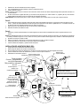
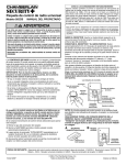
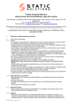
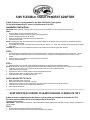
120V FLEXIBLE TRACK PENDENT ADAPTOR
Adapts direct wire or track pendants for use with 120V Flexible Track system.
For use with Hampton Bay EC series line flexible track. 60 Hz 120V
Installation Instructions:
IMPORTANT: Before installing, disconnect power by turning off the circuit breaker or by removing the fuse at the fuse box.
Step1:
1. Open the adaptor cover by removing the set screw.
2. Loosen the three set screws on the lower portion of the wiring terminal.
3. Determine the desired location of the pendant.
4. When the desired length is established, mark the pendant wire.
5. Cut the wire at the mark.
NOTE: If installing more than one pendant and the same height is desired for all pendants make sure the mark on all pendants are at the
same length before cutting.
6. The pendant wire has three (3) smaller wires running inside of it. Remove 1 ½” of the outer insulation exposing the three (3) smaller
wires inside.
CAUTION: Be careful not to cut or damage the insulation on the inside wires when removing the outer insulation.
STEP2:
1.
2.
3.
Pull the pendant wire through the bottom hole in the pendant adapter, and then secure the strain relief to the pendant wire. (NOTE:
Do not fully tighten the strain relief set screw, but secure with only 2 or 3 rotations so that the pendant wire can still be moved as
needed.
Remove a 3/8 inch of the insulation on all three (3) of the smaller wires.
Twist the copper wire strands.
STEP 3:
1. Carefully identify and connect the 3 wires following the pendant wiring instructions included with the pendant.
NOTE: Please Read all instruction of the pendant head (sold separately), to identify polarity of the wires, then connect Live to Live, Neutral
to Neutral, Ground to Ground. If you have any doubt, please contact or consult a qualified electrician.
2. Tighten screws to secure the wire.
3. Slide the strain relief to a suitable position on the wire and tighten the screws.
4. Position the strain relief to its original position in the adaptor.
5. Close the adaptor cover, and tighten the set screw.
INSTALLING ADAPTER TO TRACK:
1.
2.
3.
4.
5.
Make sure that the power is turned off.
Remove the retaining cap on the power connector.
Open the power connector cover and align the two slots of the track to the two tabs on the power connector.
Close the power connector cover and replace the retaining cap.
Restore the electrical power.
ADAPTADOR DE ACCESORIO COLGANTE PARA RIEL FLEXIBLE DE 120 V
Adapta accesorios colgantes para cable directo o riel para usar con sistemas de riel flexible de 120 V
Para usar con los sistemas de riel serie Hampton Bay de 60 Hz 120 V
Instrucciones de instalación:
IMPORTANTE: Antes de realizar la instalación, corte la alimentación eléctrica general con el interruptor principal o quitando los fusibles en la
caja de fusibles.
Paso 1:
1.
2.
Abra la cubierta del adaptador retirando el tornillo de fijación.
Afloje los tres tornillos de fijación de la porción inferior del terminal de cableado.
3. Determine la ubicación deseada del accesorio colgante.
4. Una vez establecida la longitud deseada, marque el cable del accesorio.
5. Corte el cable en la marca.
NOTA: Si deseara colgar más de un accesorio a la misma altura, antes de cortar los cables de bajada asegúrese de que estén marcados a la
misma distancia.
6. El cable del accesorio colgante tiene tres (3) conductores más pequeños en su interior. Retire 1 ½ pulgadas (38 mm) de la aislación
externa dejando expuestos los tres (3) conductores más pequeños del interior.
PRECAUCIÓN: Tome precauciones para no cortar ni dañar la aislación de los cables internos cuando quita la aislación externa.
Paso 2:
1.
2.
3.
Pase el cable del accesorio colgante a través del orificio inferior del adaptador del accesorio y luego fije al cable la protección contra
tirones. (NOTA: No apriete totalmente el tornillo de fijación de la protección contra tirones, sujétela sólo con 2 ó 3 vueltas de modo que
el cable del accesorio colgante pueda moverse aún según sea necesario.
Retire 3/8” (9 mm) de la aislación de cada uno de los tres (3) cables pequeños.
Retuerza las hebras del alambre de cobre
Paso 3:
1.
Identifique y conecte cuidadosamente los 3 cables siguiendo las instrucciones de cableado del accesorio colgante incluidas con el
mismo.
NOTA:Lea detenidamente todas las instrucciones del cabezal del accesorio colgante (vendido por separado), para identificar la polaridad de
los cables y conéctelos luego vivo con vivo, neutro con neutro y tierra con tierra. Si tiene alguna duda, consulte a un electricista profesional.
2. Apriete los tornillos para sujetar el cable.
3. Deslice la protección contra tirones a una posición adecuada en el cable y apriete los tornillos.
4. Coloque la protección contra tirones en su posición original en el adaptador.
5. Cierre la cubierta del adaptador y apriete el tornillo de fijación.
INSTALACIÓN DEL ADAPTADOR EN EL RIEL:
1.
2.
3.
4.
5.
Asegúrese de que la alimentación está desconectada.
Retire la tapa de retención del conector de alimentación.
Abra la cubierta del conector de alimentación y alinee las dos ranuras del riel con las dos lengüetas del conector.
Cierre la cubierta del conector de alimentación y vuelva a colocar la tapa de retención.
Retaining cap
Restablezca la alimentación eléctrica.
Tapa de retención
Power connector cover
Cubierta del conector de alimentación
Power connector
Conector de alimentación
Track (Sold Separately)
Riel (vendido por separado)
Set screw
Tornillo de fijación
Step 1
Paso 1
Adaptor cover
Cubierta del adaptador
Align the two slots of the track to the two
tabs on the power connector.
Alinee las dos ranuras del riel con las dos
lengüetas del conector de alimentación.
Step3
Paso 3
Black wire (live)
Cable negro (vivo)
Green wire (grounding)
Cable verde (tierra)
White wire (neutral)
Cable blanco (neutro)
Wiring terminal
Terminal de cableado
Pendant wire
Cable del accesorio colgante
Step 2
Paso 2
1”
3/8”
Strain relief
Protección contra tirones
Screw
Tornillo
Track pendant
Accesorio colgante para riel
(Sold Separately)
(Vendido por separado)