1
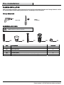
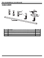
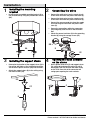
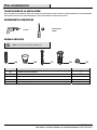
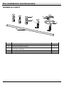
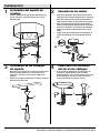
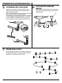
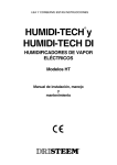
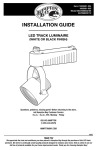
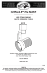
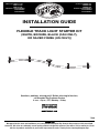
US Item #1000000-922
1000000-948
1000000-924
US Model #847658004017
847658004048
847658004031
CAN Item #1000777-349
1000777-350
1000776-346
CAN Model #847658004055
847658004062
847658004024
INSTALLATION GUIDE
FLEXIBLE TRACK LIGHT STARTER KIT
(WHITE, BRONZE, BLACK (CAN ONLY),
OR SILVER FINISH (US ONLY))
Questions, problems, missing parts? Before returning to the store,
call Hampton Bay Customer Service
8 a.m. - 6 p.m., EST, Monday - Friday
855-HD-HAMPTON
(1-855-434-2678)
HAMPTONBAY.COM
77003
THANK YOU
We appreciate the trust and confidence you have placed in Hampton Bay through the purchase of this track light
starter kit. We strive to continually create quality products designed to enhance your home. Visit us online to see our
full line of products available for your home improvement needs. Thank you for choosing Hampton Bay!
Table of Contents
Hardware Included ..................................... 3 Package Contents ...................................... 4 Installation ............................................. 5 Table of Contents ..................................2 Safety Information .................................2 Warranty .................................................2 Pre-Installation ......................................3 Planning Installation................................... 3 Tools Required ........................................... 3 Safety Information
Read these installation instructions and review the
diagrams thoroughly before installing the track
system. Save these instructions and refer to them
when additions to or changes in the track
configuration are made.
WARNING: To reduce the risk of fire and electric
shock, do not attempt to connect power tools,
extension cords, appliances, and the like to the track.
Do not attempt to energize anything other than
lighting track luminaires on the track.
□
This track light is rated at 120 volts, 60Hz,
Max. 5A.
□ Only use luminaire assemblies marked for
use with Hampton Bay’s 77003 track system.
1. Do not cut any track section.
CAUTION: Do not install this track in damp or wet
locations.
2. Read all of these installation instructions before
installing the track system.
CAUTION: Do not install any luminaire assembly
closer than 6 in. from any curtain, or similar
combustible material.
CAUTION: Do not install any part of this luminaire
less than 5 ft. above the floor.
3. Save these instructions and refer to them when
additions to or changes in the track
configuration are made.
CAUTION: Pendant-mounted track intended to be
installed by the stems only are to be mounted by
cable; the stems are to be mounted every 1 foot
along the track.
WARNING: Disconnect electrical power before
adding to or changing the configuration of the track.
Warranty
LIMITED WARRANTY
The manufacturer warrants this product to be free from defects in materials and workmanship for a period of three
(3) years from date of purchase. This warranty applies only to the original consumer purchaser and only to products
used in normal use and service. If this product is found to be defective, the manufacturer's only obligation, and your
exclusive remedy, is the repair or replacement of the product at the manufacturer's discretion, provided that the
product has not been damaged through misuse, abuse, accident, modifications, alterations, neglect, or mishandling.
This warranty shall not apply to any product that is found to have been improperly installed, set-up, or used in any
way not in accordance with the instructions supplied with the product. This warranty shall not apply to a failure of
the product as a result of an accident, misuse, abuse, negligence, alteration, or faulty installation, or any other
failure not relating to faulty material workmanship. The manufacturer specifically disclaims any liability and shall not
be liable for any consequential or incidental loss or damage, including labor/expense costs involved in the
replacement or repair of said product.
Contact the Customer Service Team at 855-HD-HAMPTON (1-855-434-2678) or visit www.Hamptonbay.com.
2
Pre-Installation
PLANNING INSTALLATION
Before you begin installation, check to ensure all parts listed in the Hardware Included and Package Contents section
are contained within the packaging and that there is no damage to any of the parts.
TOOLS REQUIRED
Phillips
screwdriver
Power drill
HARDWARE INCLUDED
NOTE: Hardware not shown to actual size.
AA
Part
BB
CC
Description
EE
DD
Quantity
AA
Junction Box Screw
2
BB
Wire Connector
3
4
CC
Wood Screw
DD
Plastic Anchor
4
EE
Canopy Screw (Preassembled to Power Feed Stem (B))
2
3
HAMPTONBAY.COM
Please contact 1-877-527-0313 for further assistance.
Pre-Installation (continued)
PACKAGE CONTENTS
D
A
C
B
E
Part
Description
Quantity
A
Mounting Bracket (preassembled to Power Feed Stem (B))
1
B
Power Feed Stem
1
C
Decorative Collar (preassembled to Power Feed Stem (B)/Support Stem (D))
5
D
Support Stem
4
E
Track Rail
1
4
Installation
1
Installing the mounting
bracket
2
□ Install the preassembled mounting bracket (A) to
the junction box by using the junction box screws
(AA).
Connecting the wires
□ Connect the white wire from the supply circuit
to the white wire from the power feed stem (B).
□ Connect the black wire from the supply circuit
to the black wire from the power feed stem (B).
□ Connect the green ground wire from the supply
circuit to the green wire from the power feed
stem (B).
□ Secure the connections with wire connectors
(BB) and gently tuck the wires into the outlet
box.
□ Attach the power feed stem (B) to the mounting
bracket (A) using the canopy screws (EE).
A
A
BB
AA
B
EE
3
4
Installing the support stems
□ Determine the location of the support stems (D) in
the ceiling, drill holes at the installation locations,
and insert the plastic anchors (DD) into the holes.
□ Attach the support stems (D) to the ceiling using
the wood screws (CC).
Opening the track contacts
on the stems
□ On the power feed stem (B) and support stems
(D), unthread the decorative collar (C) until it
disengages from the threads and slides freely
on the shaft. One side of the connector will
swing open exposing the track contacts.
DD
B
D
C
CC
D
5
HAMPTONBAY.COM
Please contact 1-877-527-0313 for further assistance.
Installation (continued)
5
6
Attaching the track rail
Closing the track contacts
□ Close the connector tight and rethread the
decorative collar (C) to lock the track contacts
closed.
□ Ensure that the ground side of the track rail (E)
(exposed copper wire on top of the track rail) is
facing the ceiling.
□ Align and insert the contacts on the support stems
(D) with the contact channel on the track rail (E),
making sure the “N” line contact inserts into the
upper channel, the “L” line contact inserts into the
lower channel, and the ground tab (1) rests on the
copper ground on top of the track rail (E).
D
B
C
B
N
E
1
E
L
D
E
7
Shaping the track
□ Refer to the following figure for recommended
shapes. Do not make any sharp bends in the track.
Do not bend the track more than 90 degrees within a
10 in. portion of the track.
6
Questions, problems, missing parts? Before returning to the store,
call Hampton Bay Customer Service
8 a.m.- 6 p.m., EST, Monday-Friday
855-HD-HAMPTON
(1-855-434-2678)
HAMPTONBAY.COM
Retain this manual for future use.
Núm. de artículo Canadá
1000777-349
1000777-350
1000776-346
Núm. de modelo Canadá
847658004055
847658004062
847658004024
Núm. de artículo EE. UU. 1000000-922
1000000-948
1000000-924
Núm. de modelo EE. UU. 847658004017
847658004048
847658004031
GUÍA DE INSTALACIÓN
JUEGO DE INTERRUPTOR DE ENCENDIDO DE
LÁMPARA DE RIEL FLEXIBLE
(ACABADO BLANCO, BRONCE, NEGRO (SOLAMENTE CANADÁ),
O ACABADO PLATA (SOLAMENTE EE. UU.))
¿Tiene preguntas, problemas, o faltan piezas? Antes de regresar a la tienda,
llame a Servicio al Cliente de Hampton Bay
de lunes a viernes de 8 a.m. a 6 p.m., hora local del Este
855-HD-HAMPTON
(1-855-434-2678)
HAMPTONBAY.COM
77003
GRACIAS
Apreciamos la confianza que ha depositado en Hampton Bay por la compra de este juego de interruptor de encendido de lámpara de
riel. Nos esforzamos por crear continuamente productos de calidad diseñados para mejorar su hogar. Visítenos en internet para ver
nuestra línea completa de productos disponibles para sus necesidades de mejorar su hogar. ¡Gracias por elegir a Hampton Bay!
Tabla de contenido
Herraje incluido.................................................... 3
Contenido del paquete ......................................... 4
Instalación ...................................................... 5
Tabla de contenido ........................................ 2
Información de seguridad ............................. 2
Garantía .......................................................... 2
Pre-instalación ............................................... 3
Planificación de la instalación ..............................3
Herramientas requeridas ......................................3
Información de seguridad
Lea estas instrucciones de instalación y revise los
diagramas por completo antes de instalar el sistema de riel.
Guarde estas instrucciones y consúltelas cuando se hagan
adiciones o cambios en la configuración del carril.
ADVERTENCIA: Para reducir el riesgo de choque
eléctrico, no intente conectar herramientas
eléctricas, cables de extensión ni cosas similares en
el riel. No intente energizar nada que no sean
luminarias para riel en el riel.
□
Esta bombilla de riel tiene capacidad nominal para
120 voltios, 60Hz, Máx. 5A.
□ Use solamente ensamblajes de luminarias
marcadas para ser usadas con sistema de riel de
77003 Hampton Bay.
1. No corte ninguna sección del riel.
2.
Lea todas las instrucciones de instalación antes de
instalar el sistema de riel.
3.
Guarde estas instrucciones y consúltelas cuando se
hagan adiciones o cambios en la configuración del
carril.
PRECAUCIÓN: No instale este riel en lugares
húmedos o mojados.
PRECAUCIÓN: No instale ninguna pieza de esta
luminaria a menos de 5 pies sobre el piso.
PRECAUCIÓN: No instale ningún ensamblaje de
luminaria a menos de 6 pulg. de cortinas o material
combustible similar.
PRECAUCIÓN: El riel montado en suspensión
previsto para ser instalado por los vástagos
solamente serán montados por medio de cables; los
vástagos serán montados cada 1 pie a lo largo del
riel.
ADVERTENCIA: Desconecte la energía eléctrica
antes de agregar o cambiar la configuración del riel.
Garantía
GARANTÍA LIMITADA
El fabricante garantiza que este producto está libre de defectos en materiales y mano de obra por un periodo de tres (3) años a partir
de la fecha de compra. Esta garantía aplica únicamente al comprador consumidor final y únicamente para los productos usados en
condiciones de uso y servicio normal. Si este producto está defectuoso, la única obligación del fabricante y la única reparación, es
reparar o reemplazar el producto a discreción del fabricante, siempre y cuando el producto no ha sido dañado por mal uso, abuso,
accidente, modificaciones, alteraciones, negligencia o mal manejo. Esta garantía no aplicará a ningún producto que se detecte que
se haya instalado, configurado o usado incorrectamente de alguna manera que no sea de acuerdo con las instrucciones
proporcionadas con el producto. Esta garantía no aplicará a fallas del producto como resultado de un accidente, mal uso, abuso,
negligencia, alteración o instalación incorrecta o cualquier otra falla no relacionada a una falla por fabricación material. El fabricante
renuncia específicamente a cualquier responsabilidad civil y no se hará responsable por daños y perjuicios, por pérdida o daños
accesorios, incluidos los gastos de mano de obra u otros gastos relacionados al reemplazo o reparación de dicho producto.
Póngase en contacto con el Equipo de Servicio al Cliente llamando al 1-855-434-2678 o visite www.Hamptonbay.com.
2
Pre-instalación
PLANIFICACIÓN DE LA INSTALACIÓN
Antes de comenzar la instalación, revise para asegurarse de que todas las piezas listadas en Herraje Incluido y la sección Contenido
del Paquete estén presentes dentro del paquete y que no hayan daños en ninguna de las piezas.
HERRAMIENTAS REQUERIDAS
Destornillador
Phillips
Taladro
HERRAJE INCLUIDO
NOTA: No se muestra el herraje en el tamaño real.
AA
Pieza
BB
CC
Descripción
EE
DD
Cantidad
AA
Tornillo de caja de empalmes
2
BB
Conector de cable
3
CC
Tornillo para madera
4
DD
Ancla plástica
4
EE
Tornillo del dosel (preensamblado al Vástago de alimentación de energía (B))
2
3
HAMPTONBAY.COM
Para obtener asistencia, póngase en contacto llamando al 1-877-527-0313.
Pre-instalación (continuación)
CONTENIDO DEL PAQUETE
D
A
C
B
E
Pieza
Descripción
Cantidad
A
Soporte de montaje (preensamblado al Vástago de alimentación de energía (B))
1
B
Vástago de alimentación de energía
1
C
Collarín decorativo (preensamblado al Vástago de alimentación de energía
(B)/Vástago de soporte (D))
5
D
Vástago de soporte
4
E
Riel de pista
1
4
Instalación
1
□
Instalación del soporte de
montaje
Instale el soporte de montaje preensamblado (A) en la
caja de empalmes usando los tornillos de la caja de
empalmes (AA).
2
Conexión de los cables
□
□
□
□
□
Conecte el cable blanco del cirtuito de alimentación al
cable blanco del vástago de alimentación de energía (B).
Conecte el cable negro del cirtuito de alimentación al
cable negro del vástago de alimentación de energía (B).
Conecte el cable verde del cirtuito de alimentación al
cable verde del vástago de alimentación de energía (B).
Asegure las conexiones con conectores de cable (BB) y
empuje con cuidado el cableado dentro de la caja de
salida.
instale el vástago de alimentación de energía (B) en el
soporte de montaje (A) usando los tornillos del dosel
(EE).
A
A
BB
B
AA
EE
3
□
□
Instalación de los vástagos
de soporte
Determine la ubicación de los vástagos de soporte (D) en
el techo, perfore agujeros en las ubicaciones de la
instalación e inserte las anclas plásticas (DD) en los
agujeros.
Instale los vástagos de soporte (D) en el techo usando los
tornillos para madera (CC).
4
□
Cómo abrir los contactos
del riel en los vástagos
En el vástago de alimentación de energía (B) y los
vástagos de soporte (D),desensarte el collarín
decorativo (C) hasta que se desenganche de los hilos y
deslice líbremente en el eje. Un lado del conector
oscilará exponiendo los contactos del riel.
B
DD
D
C
CC
D
5
HAMPTONBAY.COM
Para obtener asistencia, póngase en contacto llamando al 1-877-527-0313.
Instalación (continuación)
5
□
□
6
Instalación del riel de pista
Asegúrese de que el lado de tierra del riel de pista (E)
(cable de cobre expuesto en la parte superior del riel de
pista) esté mirando al techo.
Alinee e inserte los contactos en los vástagos de soporte (D)
con el canal de contacto en el riel de pista (E),
asegurándose de que el contacto de la línea “N” se inserte
en el canal superior, el contacto de la línea “L” se inserte
en el canal inferior y la pestaña de tierra (1) descanse en
el tierra de cobre en la parte superior del riel de pista (E).
B
□
Cierre de los contactos
del riel
Cierre el conector apretadamente y ensarte de nuevo
el collarín decorativo (C) para bloquear los contactos
del riel cerrados.
D
B
C
N
1
E
E
L
D
E
7
□
Dando forma al riel
Consulte la siguiente figura para las formas recomendadas.
No haga dobleces filosos en el riel. No doble el riel más de
90 grados en una porción de 10 pulg. del riel.
6
¿Tiene preguntas, problemas, o faltan piezas? Antes de regresar a la tienda,
llame a Servicio al Cliente de Hampton Bay
de lunes a viernes de 8 a.m. y 6 p.m., hora local del Este
855-HD-HAMPTON
(1-855-434-2678)
HAMPTONBAY.COM
Conserve este manual para uso futuro.