1
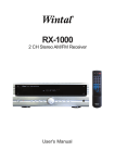
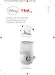
Faros
Instrucciones de Instalación
TRACK HEAD
Por favor, lea cuidadosamente y guarde estas instrucciones, ya que las podría necesitar posteriormente.
INSTALLATION INSTRUCTIONS
Please read carefully and save these instructions, as you may need them at a later date.
SEGURIDAD
ADVERTENCIA:RIESGO DE ELECTROCUCIÓN
Desconecte el suministro de electricidad antes
de instalar el juego de alumbrado de riel
SAFETY
WARNING:RISK OF ELECTRIC SHOCK.
Disconnect the electrical supply circuit to the track
Before installing light kit
GENERAL
Todas las conexiones eléctricas deben de estar en conformidad con los códigos locales, ordenanzas o los códigos elétricos
nacionales. Si no está familiarizado con los métodos de instalación de alambrado elétrico, solicite los servicios de un electricista
autorizado. Antes de comenzar la instalación, desconecte la energía eléctrica apagando el cortacircuitos o removiendo el fusible
de la caja de fusibles. Cortar la alimentación al circuito solamente con la llave de luz, no es suficiente para prevenir una
electrocución.
NOTA: Las importantes guías de seguridad e instrucciones que aparecen en este manual no están diseñadas para cubrir todas
las posibles condiciones y situaciones que puedan ocurrir. Entiéndase que el sentido común, la precaución y el cuidado son
factores que no pueden incluirse en producto alguno. Estos factores deben de ser provistos por la(s) persona(s) que instalan esta
unidad.
INSTRUCCIONES DE SEGURIDAD IMPORTANTES
1.
2.
3.
4.
5.
6.
7.
8.
9.
10.
Lea todas las instrucciones.
Guarde estas instrucciones y remítase a ellas cuando se realicen agregados o cambios en la configuración del sistema de
riel.
No instale ninguna parte del sistema de riel a menos de 7pies (2.2 m) sobre el nivel del piso.
No instale ningún juego de accesorios a una distancia menor de 6 pulgadas (15.25cm) de cualquier cortina o material
combustible similar.
No intente alimentar con el riel nada que no sea accesorios de iluminación. para reducir el riesgo DE INCENDIO,
DESCARGA ELÉCTRICA, Por favor, no trate de conectar al riel herramientas mecánicas, cables de prolongación,
artefactos ni productos similares
¡La bombilla encendida está caliente! Desconecte la energía eléctrica y deje que se enfríe antes de reemplazar la
lámpara.No toque la bombilla en ningún momento. Use un trapo blando o herramientas especiales (No se suministra en
todos los modelos). La grasitud de la piel puede dañar la bombilla.
PRECAUCIÓN – Para reducir el riesgo de quemaduras durante el cambio de bombillas, retírelo del riel antes del cambio.
¡La bombilla se calienta rápidamente! Toque sólo el interruptor o el enchufe al encenderla. No toque el cristal de la bombilla
caliente.
PRECAUCIÓN – Superficie caliente, manténgala alejada de cortinas y otros materiales combustibles.
Para instalación con rieles serie EC de HAMPTON BAY únicamente.
GENERAL
All electrical connections must be in accordance with local codes, ordinances or national electrical codes. If you are unfamiliar
with methods of installing electrical wiring, secure the services of a qualified electrician. Before starting installation, disconnect
the power by turning off the circuit breaker or removing the fuse at fuse box. Turning the power off using the light switch is not
sufficient to prevent electrical shock.
NOTE: the important safeguards and instructions appearing in this manual are not meant to cover all possible conditions and
situations that may occur. It must be understood that common sense, caution and care are factors which cannot be built into
any product. These factors must be supplied by the person(s) installing this unit.
IMPORTANT SAFETY INSTRUCTIONS
Read all instructions.
Save these instructions and refer to them when additions to or changes in the track configuration are made.
Do not install any part of a track system less than 7feet(2.2m) above the floor.
Do not install any fixture assembly closer than 6inches(15.25cm) from any curtain, or similar combustible material.
Do not attempt to energize anything other than lighting track fixtures on the track. To reduce the risk of fire and
electric shock, Please do not attempt to connect power tools, extension cords, appliances and the like to the track.
6. Lighted lamp is hot! Turn off power and allow to cool before replacing lamp. Do not touch lamp at any time. Use a
soft cloth or relamping tools (Not provided for all models), Oil from skin may damage lamp.
7. CAUTION – To reduce the risk of a burn during relamping, remove from the track before relamping.
8. Lamp gets hot quickly! Contact only switch or plug when turning on. Do not touch hot lamp lens.
9. CAUTION – Hot surface, keep away from curtains and other combustible materials.
10. For installation with HAMPTON BAY EC series track only.
1.
2.
3.
4.
5.
SAVE THESE INSTRUCTIONS
CONSERVE ESTAS INSTRUCCIONES
Track Head Installation
READ & SAVE
INSTALLATION AND REMOVAL OF TRACK HEAD
IMPORTANT: Determine ground side of track (has indented groove on face and two internal copper bars)and connector(side of
connector with two metal tabs). Can only be assembled if grounds are aligned.
Note: For glass shade fixtures, please clip/push the smaller opening of the glass shade onto the socket bracket.
INSTALLATION
1.
2.
3.
4.
Push the top portion of the head adapter into the slot of the track section.
Pull down the adapter’s locking sleeve.
Turn “Ground indicator” tab towards the ground groove on track to align ground tab with ground conductor.
Adapter can move to any position along the track section. Lighting fixture will adjust to any position.
REMOVAL
1.
2.
Pull down the adapter’s locking sleeve.
At the same time, rotate the adapter 90 degrees and remove from track.
INSTALLATION AND REMOVAL OF BULB (not provided on all models)
1. Turn the power off. Make sure that the bulb is cool before relamping the fixture.
2. Remove the head from the track. The track head sleeve must be pulled down the twist1/4 turn. For low volt track heads, pull down on
spring tab while twisting.
3. Twist to remove bulb from the socket, Replace with new bulb. To insert bulb, Rotate the bulb until it is secured. Use relamping tool
(Not provided for all models) if necessary to remove and install bulbs.(Note: Keep relamping tool for future use)
4. Replace the track head onto the track. Pull down the locking sleeve and reverse the 1/4 turn.
CAUTION: Please refer to the re-lamping label located on the fixture for recommended maximum wattage.
NOTE(FOR LOW VOLTAGE TRACK HEAD): This equipment has been tested and found to comply with Part 18 of the FCC Rules. This equipment
generates, uses and can radiate radio frequency energy and if not installed and used in accordance with the instructions, may cause harmful
interference to radio communications. However, there is no guarantee that interference will not occur in a particular installation. If this equipment does
cause harmful interference to radio or television reception, which can be determined by turning the equipment off and on, the user is encouraged to try
to correct the interference by one or more of the following measures:
Reorient or relocate the receiving antenna.
- Increase the separation between the equipment and receiver.
Connect the equipment into an outlet on a circuit different from that to which the receiver is connected
Changes or modifications not expressly approved by the party responsible for compliance could void the user’s authority to operate the equipment.
Instalación de cabezales de riel
Lea y Conserve
INSTALACIÓN Y DESMONTAJE DEL CABEZAL DEL RIEL
IMPORTANTE: Determine cuál es el lado a tierra del riel (tiene una ranura en el lado anterior y dos barras interiores de cobre) y del
conector (el lado con dos lengüetas de metal). A pesar de no ser un accesorio con conexión a tierra. el mismo podrá ensamblarse
únicamente si los lados a tierra eatán alineados.
Nota: En el caso de artefactos con pantalla de vidrio, enganche/presione la abertura más pequeña de la pantalla en el soporte del
portalámpara.
INSTALACIÓN
1.
2.
3.
4.
Introduzca a presión la porción superior del adaptador del cabezal en la ranura de la sección del riel.
Tire del manguito de bloqueo del adaptador hacia abajo.
Gire la pestaña “indicadora de tierra” hacia la acanaladura de tierra del riel para alinearla con el conductor de tierra.
El adaptador se puede mover a cualquier posición a lo largo de la sección del riel. El artefacto luminoso se ajusta a cualquier
posición.
DESMONTAJE
1. Tire del manguito de bloqueo del adaptador hacia abajo.
2. Al mismo tiempo, gire el adaptador 90 grados y desmóntelo del riel.
INSTALACIÓN Y REMOCIÓN DE LA LÁMPARA (no se suministran a todos los modelos).
1. Desconecte la alimentación eléctrica. Asegúrese de que la bombilla esté fría antes de cambiarla.
2. Para remover la cabeza de la seccion de riel, la manga de la cabeza debe halarse hacia abajo y girarse 1/4 de vuelta.Para los faros de
bajo voltaje tire la lengüeta hacia abajo mientras le da vuelta.
3. Gire la bombilla para retirarla del zócalo, Reemplácela por la nueva bombilla. Para insertar la lámpara, gire la lámpara hasta que quede
sujeta.Para retirar e instalar las bombillas, use la herramienta especial(No se suministra en todos los modelos) si fuera necesario.(Nota:
Guarde la herramienta especial para uso futuro)
4. Vuelva a colocar el cabezal en el riel. Tire de la pestaña/manguito de bloqueo hacia abajo e invierta el ¼ de vuelta.
PRECAUCIÓN: Observe el valor máximo de potencia de lámpara recomendado en la etiqueta del artefacto.
AVISO(PARA CABEZAL DE RIEL DE BAJO VOLTAJE): Este aparato ha sido puesto a prueba y cumple con las normas de la FCC, Parte 18. Este
aparato genera, utiliza y puede radiar energía de alta frecuencia.y si no se instala y utiliza de acuerdo con las instrucciones, puede ocasionar
interferencias perjudiciales en radiocomunicaciones. Sin embargo, no se puede garantizar que tales interferencias no puedan ocurrir en una
determinada instalación.Si este aparato le ocasionara interferencias perjudiciales a su recepción, de radio o televisión, lo cual puede determinarse.
encendiendo v apagando, el aparato, el usuario podrá intentar corregir dicha interferencia mediante uno de los siguientes métodos.
Moviendo odesplazando la antena de recepcíon.
- Aumentando la distancia entre el aparato y el receptor.
Conectando el aparato en un tomacorrientes que pertenezca aun circuito eléctrico distinto al usado para el receptor
Cualquier cambio o modificación que no haya sido aprobado especificamente por la parte responsable de la conformidad con el reglamento.podría
anular la autorización del usuario de hacer funcionar este aparato.
713