1
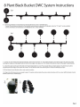
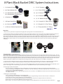
8 Plant Black Bucket DWC System Instructions
1. (1) 8 Outlet Air Pump
8.
(12) 1/2“ Grommet
2. (8) 6” Net Pot Bucket Lids
9. (9) 1/2“ Shut-Off Valve
3. (2) 5 Gallon Buckets (Master Reservoirs)
(8) 5 Gallon Buckets (Site Reservoirs)
10. (8) 1/2” Barbed “T
11. (3) 1/2” Barbed “L”
4. (2) Bucket Lids
12. (2) 1/2” Barbed “Straight”
5. (10) Super Starter Plugs
13. (1) 14” Length of 1/2“ Black Tubing
6. (8) 4” Air Stone
14. (1) 32‘ length of 1/4“ Clear Tubing
7. (1) 50 Liters ViaStone Expanded Clay
15. (1) 3’ Transparent Blue 1/2“ Tubing
Preparation:
1. Wash and rinse your ViaStone Clay Rocks thoroughly before placing them in the 6” Net Pot Bucket Lids.
fig.3
fig.2
fig.1
2. The Super Starter Plugs are provided to germinate seeds or to propagate cuttings in. Place the seeds at the recommended planting depth and
keep them moist, but not saturated with water. They should always be moist but never soggy. Seedlings generally thrive at 75-85° with
60%+ humidity. When the seedlings are ready to transplant, bury each Super Starter Plug into the 6” Net Pot Bucket Lid so that the top of the Super
Starter Plug is covered with a thin layer of ViaStone Clay Rocks. Make sure that the bottom of the seedling root system will be in contact with the
bubbling water-nutrient solution. As the roots grow, decrease the water-nutrient solution level to keep the root mass from being submerged
completely.
Master
Control 1
Barbed “T”
Master
Control 2
Shut-Off
System Assembly: (See parts layout fig.1-2)
1. The Master Control Buckets will be the 5 Gallon Buckets that have 2 pre-drilled holes (the other eight 5 Gallon Buckets will have only 1). Take one
Master Control Bucket and insert the ½” Grommet into the pre-drilled hole in the bottom of the side wall, then insert one side of the Barbed “L” until it
is firmly seated inside of the grommet with the exposed end facing up. Now push the 18“ length of transparent blue tubing over the open end of the
Barbed “L”. This length of tubing will be used as your water level indicator and will allow you to visually inspect the water level inside of the system
without removing the lid. Make sure the transparent blue tubing is pointed up. Now, repeat for the second Master Control Bucket.
2. Insert the other ½” Grommets into the second pre-drilled holes in the Master Control Buckets, then insert the ½” Barbed Straights until firmly
secured and attach a 6“ length of ½” Black Tubing to each of the Master Control Buckets to the open end of the ½” Barbed Straights.
3. Use the top of a Barbed “T” to connect the 6“ pieces of 1/2” Black Tubing together. Now take the open perpendicular end of that Barbed “T” and
attach a small length of the ½” Black Tubing to it, then insert a ½” Shut-Off Valve into the open end until firmy secured. (fig. 3)
4. Preparing the Site Reservoir Buckets
- Place the remaining ½” Grommets into the pre-drilled holes in the bottom of the side wall for the remaining eight 5 Gallon Buckets.
- Insert the remaining ½” Shut-Off Valves into the ½” Grommets. If you have difficulty, a small dab of liquid dish soap can be used as a lubricant
(it will need to be washed off when finished).
- Cut eight 9“ -12” lengths of the ½” Black Tubing and attach one to each of the ½” Shut-Off Valves that have been inserted into the bottom of the
four 5 Gallon Buckets.
5. Building the ½” Manifold (fig. 4)
- Cut the remaining ½” Black Tubing into eight equal lengths.
- Starting at the Master Control Buckets’ 1/2“ Shut-Off Valve, attach 1 length of tubing and to the other side attach a ½” Barbed “T.”
- To the other side of the “T” attach another piece of ½” Black Tubing.
- Attach another “T” to the Black Tubing making sure the perpendicular end points in the opposite direction of the first “T.”
- Repeat this process until all of the Barbed “T” pieces have been used.
- Once all of the “T’s” have been used, connect the last length of ½” Black Tubing from the “T” to the other side of the ½” Barbed “L.”
Page 1