1
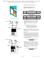
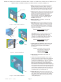
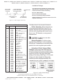
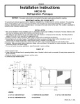
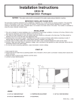
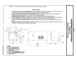
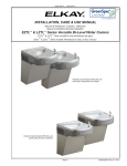
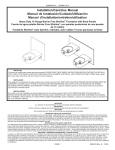
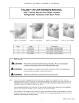
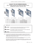
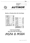
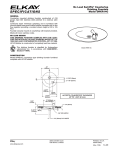
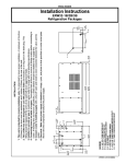
ERPB2-8C, ERPB2-8RAC, ERPBV2-8C, ERPBV2-8RAC, LRPB2-8C, LRPB2-8RAC, ERPB2-8C*2C, ERPB2-8C*3C
ERPB2-8GRNC*A, ERPB2-8GRNRAC*A, LRPB2-8GRNC*A, LRPB2-8GRNRAC*A
INSTALLATION, CARE & USE MANUAL
TM
TM
SWIRLFLO Refrigerated fountains with FLEXI-GUARD
ERPB2-8C
ERPB2-8RAC
INSTALLER
Review these instructions before beginning installation. Be sure that installation
conforms to all plumbing, electrical and other applicable codes.
When installation is complete, ensure these instructions are left in the plastic bag
provided inside the installed unit for future reference.
Service to be performed by authorized service personnel only.
NOTE: It is common practice to ground electrical hardware such as telephones, computers and other devices
to available water lines. This can, however, cause electrical feedback in the plumbing circuit, which
results in an “electrolysis” effect occurring in the fountain. This may result in water which has a metallic
taste to it or has a noticeable increase in the metallic content of the water.
When inspecting plumbing circuit, remember the line may be grounded some distance from the
installation, and may occur outside the building or area in which the unit is being installed.
This condition can be avoided (in most cases) by using recommended materials during installation. Any
drain fittings provided by the installer should be made of plastic which will electronically isolate the
fountain from the remainder of the building’s plumbing circuits.
Page 1
97924C (Rev. G - 2/12)
97924C (Rev. G - 2/12)
LEGEND
A = 1/4” O.D. Tube - Water Outlet Connection
B = 3/8” O.D. Tube - Water Inlet Connection
C = 1-1/4” Waste Tube
D = ELECTRICAL INLET
Figure 1 - Rough-in Dimensions
Model LRPB2-8C
Model LRPB2-8RAC
ERPB2-8C, ERPB2-8RAC, ERPBV2-8C, ERPBV2-8RAC, LRPB2-8C, LRPB2-8RAC, ERPB2-8C*2C, ERPB2-8C*3C
ERPB2-8GRNC*A, ERPB2-8GRNRAC*A, LRPB2-8GRNC*A, LRPB2-8GRNRAC*A
Page 2
ERPB2-8C, ERPB2-8RAC, ERPBV2-8C, ERPBV2-8RAC, LRPB2-8C, LRPB2-8RAC, ERPB2-8C*2C, ERPB2-8C*3C
ERPB2-8GRNC*A, ERPB2-8GRNRAC*A, LRPB2-8GRNC*A, LRPB2-8GRNRAC*A
REQUIRED TOOLS AND MATERIALS
These tables show special tools and/or
additional materials (not provided) which are
necessary to complete installation of these
units:
Special Tools
Item
Description
Quantity
NONE
Additional Materials
Item
Figure 2 - Chiller Installation
Description
1
Unplated copper inlet pipe
2
Service Stop
Quantity
1. Install chiller: Remove front panel of chiller. Remove
and discard cardboard inner pack from between
compressor and side panel. Slide chiller onto the
shelf and position it to the left as per dimensions in
Figure 1.
TO BUBBLER
26
26
Note: Building construction must allow for
adequate air flow on both sides, top and
back of chiller. A minimum of 4” (102mm) on
both sides and top is required. See chiller
installation for additional instructions.
27
28
CHILLER
OUTLET
CHILLER
INLET
2. Make water supply connections. Install a shut-off valve
and union connection to building water supply (valve and
union not provided). Turn on water supply and flush the
line thoroughly.
3. ERPB Models: Make connection between remote chiller
and building supply line. Inlet port is marked on the chiller
(1/4” O.D. copper tube). Bend the copper tube (provided)
at an appropriate length from chiller to opening in frame.
Install the in-line strainer (provided with chiller) by pushing
it until it reaches a positive stop, approximately 3/4” (19mm)
on the marked chiller inlet port. Connect building supply
line to strainer. (See Figure 3)
Figure 3 - ERPB Tube Routing
Caution: DO NOT SOLDER tubes inserted
into the strainer as damage to
o-rings may result.
TO BUBBLER
26
26
27
42
26
CHILLER
OUTLET
WATER
INLET
4. LRPB Models: Mount filter head assembly to side of
chiller (See Figure 4). Make connections between filter
and building supply line (3/8” O.D. tube not porvided).
Inlet port is marked on the chiller (1/4” O. D. copper tube).
Install a 1/4” x 1/4” union (provided) on the marked chiller
inlet port. Insert the 1/4” poly tubing (provided) into the
fitting on filter and connect the union to the chiller.
(See Figure 4)
Caution: DO NOT SOLDER tubes inserted
into the strainer as damage to
o-rings may result.
Figure 4 - LRPB Tube Routing
Page 3
97924C (Rev. G - 2/12)
ERPB2-8C, ERPB2-8RAC, ERPBV2-8C, ERPBV2-8RAC, LRPB2-8C, LRPB2-8RAC, ERPB2-8C*2C, ERPB2-8C*3C
ERPB2-8GRNC*A, ERPB2-8GRNRAC*A, LRPB2-8GRNC*A, LRPB2-8GRNRAC*A
5. Hang the upper panel on the mounting frame hanger. Be
sure that the panel is engaged with hanger at the top of
frame before releasing it. Align holes in the panel with holes
in the mounting frame. Install two (2) #10-24 x 5/8” (16mm)
screws (Item 29 - Figure 5) in holes and tighten securely.
29, 30, 31, 32
6. Install the fountain. Remove the screw (Item 30) from cover
plate and slide cover plate (Item 14) toward basin. Mount the
fountain to the upper panel and frame with (4) 5/16” x 1”
(25mm) bolts (Item 33), brackets (Item 36) and nuts
(Item 35) provided. Tighten securely. Brackets (Item 36)
must be installed as shown to properly support
fountains. (See Figure 6)
34
7. Attach waste tube (1-1/4” O.D.) to 1-1/4” O.D. slip
trap (provided by others).
8. ERPB Models: Make connections between remote chiller
outlet tube and fountain. Outlet port is marked on the chiller
(1/4” O.D. copper tube). Install a 1/4” x 1/4” tee (provided)
on the marked chiller outlet port. Insert the 1/4” poly tubing
coming from the fountain into the union. Turn on the water
supply and check for leaks.
Figure 5 - Upper Panel Installation
37
CAUTION: DO NOT SOLDER tubes inserted
into the strainer as damage to
o-rings may result.
LRPB Models: Make connections between remote chiller
outlet tube and fountain. Outlet port is marked on the
chiller (1/4” O.D. copper tube). Install a 1/4” x 1/4” tee
(provided) on the marked chiller outlet port. Insert the 1/4”
poly tubing coming from the fountain into the union.
16
35
41
CAUTION: DO NOT SOLDER tubes inserted
into the strainer as damage to
o-rings may result.
40
34
9. These products are designed to operate on 20-105
PSIG supply line pressure. If inlet pressure is above
105 PSIG, a pressure regulator must be installed in
the supply line.
View From Rear
CAUTION: Any damage caused by connecting
these products to a supply line with
pressure lower than 20 PSIG or
higher than 105 PSIG IS NOT
covered under warranty.
Figure 6 - Fountain Installation
10. Make electrical connections to the chiller. See
chiller instructions.
11. Check stream height from bubbler. Stream height is
factory set at 35 PSI. If supply pressure varies greatly from
this, remove push button (Item 17 - Figure 11) and adjust
the screw on the regulator (Item 19 - Figure 11). To remove
push button, remove set screw from bottom of sleeve
(Item 33). Insert a small punch in screw hole and push up
while grasping the push buttom and pull forward removing
the push button. Clockwise adjustment will raise stream height
and counterclockwise movement will lower stream height. For
best adjustment stream should hit basin approximately 6-1/2”
from the bubbler. Reassemble push button by pushing in on
button until the push button catches in the sleeve. Reinstall
the setscrew (Item 33) in the sleeve (Item 15).
28
Figure 7 - Lower Panel Installation
97924C (Rev. G - 2/12)
12. Mount lower panel. Loosen the three (3) #10-24 x 5/8”
(16mm) screws (Item 29 - Figure 6) at frame bottom lip. Slide
upper tongue of lower panel under lower edge of already
installed upper panel. Tighten previously loosened screws
securely. (See Figure 7)
Page 4
ERPB2-8C, ERPB2-8RAC, ERPBV2-8C, ERPBV2-8RAC, LRPB2-8C, LRPB2-8RAC, ERPB2-8C*2C, ERPB2-8C*3C
ERPB2-8GRNC*A, ERPB2-8GRNRAC*A, LRPB2-8GRNC*A, LRPB2-8GRNRAC*A
7
7
1
2
8
8
4, 5, 6
3, 5, 6
Basin
Basin
9
9
FLEXI-GUARD® STREAMSAVER™ BUBBLER DETAIL
FLEXI-GUARD® BUBBLER DETAIL
NOTE:
When installing replacement bubbler and pedestal, tighten
nut (Item 7) only to hold parts snug in position. Do Not
Overtighten.
10
11
Basin
12
VANDAL RESISTANT BUBBLER DETAIL
Figure 8 - Bubbler Details
Page 5
97924C (Rev. G - 2/12)
ERPB2-8C, ERPB2-8RAC, ERPBV2-8C, ERPBV2-8RAC, LRPB2-8C, LRPB2-8RAC, ERPB2-8C*2C, ERPB2-8C*3C
ERPB2-8GRNC*A, ERPB2-8GRNRAC*A, LRPB2-8GRNC*A, LRPB2-8GRNRAC*A
7 When provided
2
1
6
4
3
5
Figure 9 - Filter Assembly
WaterSentry Filter Detail
®
WATERSENTRY FILTER PARTS LIST
(See Fig. 9)
ITEM NO. PART NO.
1
2
3
4
5
6
7
97924C (Rev. G - 2/12)
51294C
70792C
70823C
70822C
51299C
70818C
22490C
DESCRIPTION
Filter Head Assy.
Screw #8-18 x .75 PH
Fitting - Superseal 3/8” (10 mm)
Fitting - Superseal 1/4” (6 mm)
Filter Assy
Elbow - 3/8” (10mm)
Bracket
Page 6
ERPB2-8C, ERPB2-8RAC, ERPBV2-8C, ERPBV2-8RAC, LRPB2-8C, LRPB2-8RAC, ERPB2-8C*2C, ERPB2-8C*3C
ERPB2-8GRNC*A, ERPB2-8GRNRAC*A, LRPB2-8GRNC*A, LRPB2-8GRNRAC*A
25
See Fig. 8
13
23
See Fig. 8
24
14
36
16
26
39
34
15
Figure 10 - Fountain Body Assembly
39
17
18
43
19
20
21
22
38
Figure 11 - Push Button Assembly
Page 7
97924C (Rev. G - 2/12)
ERPB2-8C, ERPB2-8RAC, ERPBV2-8C, ERPBV2-8RAC, LRPB2-8C, LRPB2-8RAC, ERPB2-8C*2C, ERPB2-8C*3C
ERPB2-8GRNC*A, ERPB2-8GRNRAC*A, LRPB2-8GRNC*A, LRPB2-8GRNRAC*A
Installation Package
1/4" O.D. TUBE
WATER INLET
TO COOLER
3/8" O.D. UNPLATED
COPPER TUBE CONNECT
COLD WATER SUPPLY
BUILDING WATER
INLET
The components for installation are packed in three
separate boxes, regardless of the type of unit being
installed. The boxes contain the following:
Box No. 1: Wall Frame(s)
Box No. 2: Remote Chiller, ECH8
Box No. 3: Fountain(s), Arm(s) and Panels
SERVICE STOP
(NOT FURNISHED)
NOTE: WATER FLOW
DIRECTION
Additional materials, as noted in the Parts List, are also
shipped in these boxes.
Figure 12 – Water Supply Connections
PARTS LIST
ITEM NO.
1
2
3
4
5
6
7
8
9
10A
10B
11
12
13
14
15
16
17
18
19
20
21
22
23
24
25
26
27
28
29
30
31
32
33
34
35
36
37
38
39
40
41
42
43
PART NO.
56073C
98502C
40319C
40608C
50171C
50314C
56011C
55997C
75580C
98118C
98481C
100322740560
15009C
55001132
55000944
45767C
28343C
45781C
45847C
45848C
50986C
61313C
15005C
56163C
45769C
45768C
56092C
70682C
55996C
28383C
28384C
28948C
28949C
27026C
111008343890
70432C
38417001
75560C
75632C
70817C
70020C
28395C
70683C
75671C
DESCRIPTION
Bubbler Assy
Bubbler Assy (Stream Saver)
Fitting - Orifice
Fitting - Orifice (Stream Saver)
O-Ring
Orifice - Flow Straightener
Housing Assembly
Pedestal
Bubbler Locknut
Bubbler Assembly VR
Bubbler Assy. VR StreamSaver
Gasket - Black .68 x 1.03 VR
Nipple - Bubbler VR
Basin - Swirlflow
Lower Shell
Fountain Body
Cover Plate
Sleeve
Pin - Push Button
Push Button
Holder - Regulator
Regulator
Retaining Nut
Gasket - Drain
Assy - Drain/Tailpipe
Drain - Plug 1-1/2”
Poly Tubing (Cut To Length)
Tee - 1/4
Strainer (Provided with Chiller)
Back Panel RH ADA
Back Panel LH ADA
Back Panel RH ADA (Grn Spec)
Back Panel LH ADA (Grn Spec)
Lower Panel
Screw - #10-24 x .62 HHSM
Screw - #8-32 x .38 THSM
Screw - #8-18 x .37 HHSM
Screw - 5/16-18 x 1.00 HHMS
Setscrew - #10-32 x .38
Fttng - Elbow 1/4 x 1/4
Nut - Hex 5/16-18
Bracket - Support
Fitting - Union 1/4 x 1/4
Spring - Push Button
TROUBLESHOOTING & MAINTENANCE
Orifice Assembly: Mineral deposits on
orifice can cause water flow to spurt or not
regulate. Mineral deposits may be removed
from the orifice by poking with a small round
file not over 1/8” diameter, or using a small
diameter wire.
DO NOT file or cut orifice
material.
Stream Regulator: If orifice is clean,
regulate flow as in Step 11 of the installation
instructions. If replacement is necessary, see
parts list for correct regulator part number.
Actuation of Quick Connect Water
Fittings: Cooler is provided with lead-free
connectors which utilize an o-ring water seal.
To remove tubing from the fitting, relieve water
pressure, push in on the gray collar while
pulling on the tubing. (See Figure 13) To insert
tubing, push tube straight into fitting until it
reaches a positive stop (approximately 3/4”).
Figure 13 – Quick Connect Fittings
REPAIR SERVICE INFORMATION TOLL FREE NUMBER 1.800.260.6640
FOR PARTS, CONTACT YOUR LOCAL DISTRIBUTOR OR CALL 1.800.323.0620
ELKAY MANUFACTURING COMPANY • 2222 CAMDEN COURT • OAK BROOK, IL 60523 • 630.574.8484
97924C (Rev. G - 2/12)
Page 8