1
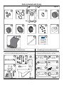
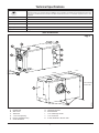
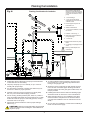
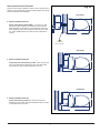
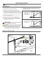
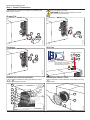
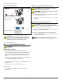
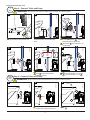
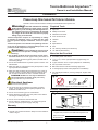
Tecma Bathroom Anywhere™
Owner’s and Installation Manual
Installation
Please keep this manual for future reference.
Read ALL these instructions before installing the Tecma Bathroom Anywhere unit.
!
Warning!
Read and understand the warnings
listed in this document before you install, operate, or service
this system. If you do not obey these warnings there is a
risk of property loss, injury, or electrocution. Do not make
any changes to this unit as this could result in property
damage, injury, or electrocution.
Thetford Corporation accepts no responsibility or liability
for damage to equipment, injury, or death that may result
from the system's improper installation, service, or operation.
Thetford Corporation recommends that plumbing and electrical work be performed by a licensed tradesperson. Local
permit and code compliance is required.
Caution: To avoid damaging property and to
! make sure the unit operates correctly, please do the
Required Tools
■ Pipe saw
■ Phillips screw driver
■ Flathead screw driver
■ 5/16" Socket wrench
■ Hammer
■ Level
■ Tape Measure
■ Drill
■ 1/2" masonry drill bit (Concrete floors)
■ 1/4" drill bit (Wood floors)
following:
■ Do not flush anything other than human organic waste
and toilet tissue. Do not flush paper towels, pre-moistened
wipes, condoms, feminine hygiene products, dental floss or
household garbage.
Materials Not Provided
■ Do not allow the Bathroom Anywhere system to freeze. See
Winterization.
■ 3" pipe extension and 3" coupler (depends on installation)
■ Make sure that any pipe work that may be exposed to freezing temperatures is insulated.
■ Ball valves sized to inlet and discharge pipe sizes
■ Make sure that plumbing fixtures attached to the pump do
not leak. If there is a power failure the pump will not operate, and this could cause the unit to overflow and flood.
■ For optimal performance, use long sweep 90° angles. Refer
to Fig. A.
■ 1-1/4",1-1/2", and 2" rigid (Schedule 40) pipe fittings, as
needed
■ Tee-wye sewer connection
■ 2" Sewage pump check valve (depends on installation)
Fig. A
CAUTION: Do NOT use one-way air admittance
valves (also known as cheater vents). Macerating
pumps need two-way air movement.
Electrical Cautions:
To ensure safe operation:
*Long Sweep
Standard Elbow
■ The pump must be connected to a properly grounded
(GFCI - ground fault circuit interrupter) receptacle on a
dedicated 15 AMP circuit.
*Two connected 45° angles can be substituted for one long sweep
ART00180-1-3
!
■ PVC/ABS primer and cement
Product Information
■ Do not use in swimming pool or marine areas.
■ Always disconnect the plug from the power source before
servicing or handling the pump.
Fig. B
ART00104
■ Do not use an extension cord with this unit!
■ Do not make any modifications to, or remove the ground
pin from, the pump's power supply cord plug.
Warranty
2
Serial
Numb
er
Location of Serial Number
■ Refer to the one-page warranty statement.
■ Record your product information. Keep for future reference.
Refer to Fig. B.
PRODUCT INFORMATION
Register this product at www.bathroomanywhere.com
Date of Purchase:
Model Serial #:
www.bathroomanywhere.com
1
Form No. 38792 Rev. D 09/22/10
Parts Included with Pump
Fig. C
#1
Pump
#2
(3x) 90-110mm
#3
(1x) 1-1/2"
#6
(1x)
#7
(1x) 60-70mm
#4
(1x) 2"
(8x)
#9
(1x)
(1x)
#13
#5
ART00119
(3x) 32-50mm
(1x)
(1x)
#8
(1x)
#11
#12
al
nu
Ma
ec
rot
it P
cu
Cir
n
tio
ec
rot
tP
ea
rh
e
Ov
h
itc
Sw
n
tio
Plumbing Purchased Separately
Parts Included with Thetford Toilet
(2x)
(2x)
#15
(2x)
#16
#20
Water Tank
ART00193-1-4
#14
ART00192
NOTE: Parts shown below are referenced in the instructions and apply
to Thetford's rear discharge toilet and water tank. Your instructions may
vary if you are installing a different rear discharge toilet.
(1x)
#10
NOTE: Plumbing components pictured below are referenced in the installation instructions. Additional plumbing
components are required based on your site.
1-1/4" Long P1
Sweep
Elbow to install
Discharge
P5
o
1-1/2" 90
Street Elbow to
install Vent
o
P2
1-1/2" 90
Street Elbow
to install Sink
Ball Valve
P6
#17
#21 Rear Discharge
Toilet
#18
(2x)
P7
Sewage Pump
Check Valve
(Flapper Type)
#19
P4
1-1/2" Elbow
to install Vent
Fig. D
2
P8
3" Coupler for 3"
Extension Pipe
Fig. E
ART00191-1-7
(2x)
o
P3
2" 90
Street
Elbow to
install Shower/Tub
Technical Specifications
C
NSF
The system has the NSF C-US certification. The National Sanitation Foundation (NSF) has tested and certified this system to be compliant with the ASME A119.2.3 and B45.1 standards for household macerating systems for the United States and Canada. This NSF certification ensures U.L. electrical compliance to U.L. 778
Standard.
US
ASME A112.3.4
CSA B45.9
Power supply
120 V
Power
600 W
Current
8.0A
Circuit Requirement
Dedicated 15 AMP
Frequency
60 Hz
Duty cycle
2.5 gpm, 10 foot lift, 1 hour on; 45 minutes off
Terms & Dimensions
Fig. F
D
G
F
H
I
E
J
K
2
Serial
Numb
er
7 1/4'"
18 5/8"
9" in
clud
Blad ing Inlet
der
11 3/8" Tall Feet
11" Short Feet
B
A
A.
B.
C.
D.
E.
F.
Rubber Feet
Side Cover
Toilet Inlet
1-1/2" Vent Opening
Knob to Separate Pump
Circuit Protection
G.
H.
I.
J.
K.
Thermal Protection
Manual Switch
1-1/4" Discharge Outlet
1-1/2" Sink Inlet
2" Sink, Bathtub or Shower Inlet
3
ART00104
C
Planning the Installation
Fig. G
1. The placement of the 120V
GFCI outlet location MUST
meet local code! Recommend
at least 40" away from bathtub
or shower and within 6' of the
pump.
Plumbing Considerations for Installation
3
2. 1-1/4" discharge
3. 1-1/2" vent connected to
outside-do NOT use one-way
"cheater" vents
4. Ensure proper slope on all
horizontal runs
12
5. Water overflow drain
4
6. 1-1/2" drain for bathtub; 2" drain
for shower
7. Platform - refer to Fig. J
2
8. Ball valve recommended for
pump discharge
9. 1-1/2" Drain
10. Optional ball valves for pump
inlets
11. 2" sewage pump flapper check
valve
12. Tee-wye sewer/septic line
connection
1
5
8
GFCI
11
10
6
10
ART00143
7
9
■ To ensure efficient waste evacuation, the pump must
have at least 3' of 1-1/4" discharge pipe before transitioning to a larger pipe size.
■ All plumbing fixtures attached to the pump must be located
on the same floor of the building.
■ The pump will pump up to 18' vertically or up to 150' horizontally with proper slope.
■ If a vertical rise is required, it should come before any horizontal run to allow for proper operation.
■ All pipes must be constructed of rigid material, such as
PVC. Do NOT use flexible pipes. All fittings should be
primed and glued. Do NOT glue pipe to rubber tank; use
clamps provided.
■ All inlets in the unit must be connected to a fixture (toilet,
sink, etc.) OR covered with the plugs provided!
■ Installing ball valves near the inlets and discharge pipe
will make it easier to remove the unit for maintenance.
■ Do not use any plumbing fixtures (sink, toilet, etc.) until the
pump is installed and tested. Be sure the fixtures do not leak
as this will cause the pump to continually operate, causing
excessive wear on the pump
■ Select the right option for your installation. Plan GFCI
electrical location and placement of all fixtures before
you begin the installation. Plan for maintenance accessibility.
■ Shower/tub must be elevated to ensure proper drainage.
Refer to Fig. J.
■ As you plan your installation, consider the accessibility to
the air vent and water supply.
!
CAUTION: Make sure all local plumbing and electrical
codes are followed when installing the Tecma Bathroom
Anywhere pump.
4
Which Installation Best Fits My Site?
OPTION #1
ART00182-1
Fig. H
There are three basic installation options. When planning the installation, note overall width of toilet and offset placement of pump;
plan for maintenance accessibility!
■ INSTALLATION OPTION #1:
16.00”
Pump and Plumbing Behind Wall - you need a 3" rigid
pipe and 3" pipe coupler (not included), and shorter foot
pads (included) to achieve the proper drainage slope. Distance between toilet outlet and pump inlet can not exceed
36". Allow additional space for side-to-side maintenance
access.
27.75”
!
3" Rigid Pipe
Not to exceed 36"
ART00182-2
OPTION #2
■ INSTALLATION OPTION #2:
20.00”
Pump Exposed and Plumbing in Wall - place the pump in
front of the wall with the plumbing in the wall. Allow additional space for side-to-side maintenance access.
OPTION #3
■ INSTALLATION OPTION #3:
ART00182-3
34.00”
20.00”
Pump and Plumbing Exposed - place the pump and
plumbing in front of the wall. Allow additional space for sideto-side maintenance access.
37.75”
5
Install Toilet and Pump
NOTE: Unless otherwise noted, steps apply to ALL installation options.
Site Preparation
■ Drill floor holes for toilet. If installing in concrete floor, install anchors but do NOT permanently secure fixtures until
instructed. Refer to Fig. I.
Complete the following before starting the installation:
■ Installation site floor finished and level within 1/8".
■ Place all components in the desired installation position;
mark footprint and bolt positions. Check for all clearances
including doors and cabinets. Also be sure to check for vertical clearance for any shower enclosure. Refer to Fig. G and
H.
Concrete Floor Installation
ART00190-1
■ Ensure that all plumbing and electrical do not interfere with
placement of bathroom fixtures.
■ Rough plumbing and electrical are completed to code.
Using Anchors: drill
2 holes using a 1/2"
masonry drill bit; then
insert Part #18.
#18
■ The placement of the 120V GFCI outlet MUST meet local code! Recommend at least 40" away from bathtub or
shower and within 6' of the pump.
!
ART00190-2
Wood Floor Installation
Warning!
Do not use an extension cord as this
is a safety hazard that can cause injury!
Using Only Screws:
drill 2 pilot holes using
a 1/4" drill bit
CAUTION: To permit proper drainage it is essential to
!
elevate the shower/tub drain to a MINIMUM of 9" above
the finished floor of the installed pump. If necessary,
remember to adjust the height of the shower/tub drain
upwards to allow proper grade for the plumbing connection to the PUMP. Plan accordingly; refer to Fig. J.
Fig. I
Shower or Tub Floor Height
Drain opening of shower or tub
!
!
IMPORTANT: Top of drain opening MUST be
elevated AT LEAST 9" above the finished floor
of the installed pump.
Fig. J
ART00194-1
9"
IMPORTANT: BE SURE
the flapper swings freely
with minimum flow by
installing
as shown.
P7
6
Install Toilet and Pump, Con't.
Step 1. Attach Connections
!
Insert the plumbing connections according to your installation plans.
Refer to Fig. C, E, and F.
!
Shower/Tub
CAUTION: Do NOT insert plumbing more than 1"
deep into plumbing openings.
CAUTION: Do NOT glue rigid plumbing to rubber
inlet. Use the provided clamps
Sink
!
#2
J
!
K
#4
P3
1-1/2"
ART00188-2
2"
ART00188-1
P2
Discharge
Vent Line
Slide over plumbing
#2
I
20.00”
P1
34.00”
#10
ART00182-2
!
#2
Pipe MUST be offset 2" from
discharge pipe!
For maintenance purposes,
leave at least 1-1/2" of straight
plumbing above #2 clamp.
1-1/4"
1-1/2"
!
ART00189-1
ART00188-3
D
Installations with Unused Inlets
Installations without Toilet
If
and
are not attached to a fitting, they MUST be covered
with the caps using clamps provided.
If C is not attached to a toilet, it MUST be covered with the cap using
clamp provided.
J
K
#2
#6
J
#4
C
1-1/2"
#5
2"
ART00088
#7
ART00091
K
#3
7
Install Toilet and Pump, Con't.
Step 2. Attach Labels
Step 4. Connect Vent to Vent Stack
Fig. K
ART00186-1
!
!
Overheat Protection
valves (also known as cheater vents). Macerating
pumps need two-way air movement.
CAUTION: The pump must be vented to the outdoors,
per your local plumbing code.
1. Measure rigid pipe from vent on pump to vent connection
(new or existing vent stack).
#12
Circuit Protection
CAUTION: Do NOT use one-way air admittance
Manual Switch
2. Connect rigid pipe to main vent stack of house or directly
outdoors.
Place label based on
installation visibility
Step 5. Connect Discharge Line
#13
Place label near toilet
ART00186-2
!
CAUTION: Pump discharge outlet has a built-in
check valve. Do NOT install an additional check valve as
this may cause the pump to malfunction.
1. Install 1-1/4" ball valve approximately 6" from pump discharge outlet. Plan for accessibility.
2. Install 1-1/4" plumbing line to house main waste line.
There must be at least 3' of run from the pump before connecting to main waste line.
!
CAUTION: To verify proper lengths for plumbing,
Note: When connecting to the sewer line, use direc-
be sure to dry-fit ALL plumbing BEFORE permanently
bonding plumbing connections! Place the pump in the
installation position and follow the steps below.
tional fittings that meet your local plumbing code.
Refer to Fig. G for Steps 3-5.
Step 3. Connect Bath/Shower/Sink
!
CAUTION: Make sure there is proper slope of all
horizontal runs!
ATTACH BATH / SHOWER
■ To permit proper drainage it is essential to elevate the
shower/tub drain to a MINIMUM of 9" above the finished
floor of the installed pump. If necessary, remember to adjust
the height of the shower/tub drain upwards to allow proper
grade for the plumbing connection to the PUMP. Refer to
Fig. J.
■ If bathtub is connected, the 2" connection can be reduced to
1-1/2" with adequate slope into the pump.
1. Measure rigid pipe from 2" pump inlet to shower/bath drain.
2. Cut pipe to fit.
3. Connect shower/tub to 2" inlet with proper slope.
ATTACH SINK
1. Measure rigid pipe from sink drain to 1-1/2" pump inlet.
2. Cut pipe to fit.
8
Install Toilet and Pump, Con't.
Step 6. Connect Toilet and Pump
IMPORTANT: Be sure the floor holes are drilled before you begin the following steps!
ART00196
1
2
3
ART00187-2-3
!
ART00187-1
Option
1
Only
#8
Replace (8X)
#3
Remove tall feet (8X)
HINT: Sit on the
toilet to attach #8
!
#9
Top of finished floor
■
! Apply soapy-water for lubrication; use
non-petroleum-based products only!
Drill wall hole. Wall hole center must be
located and sized to accommodate pipe
slope.
■! Position #3 . Then apply soapy water
to lubricate & position #8 ; use nonpetroleum-based products only!
5
!
Cannot exceed 36"
P8
6
ART00187-5
ART00187-4
4
ART00187-6
■! Be sure that #8 covers at least 1-1/2"
of toilet outlet.
P8
3"
Rigid
Pipe
!
C
#8
#3
Step 6. Connect Toilet and Pump
IMPORTANT: Be sure the floor holes are drilled before you begin the following steps!
2
3
ART00195-1
1
HINT: Sit on the toilet
to attach C
ART00195-3
!
ART00195-2
Option
2&3
Only
Insert pipe through wall; connect ends.
■! #8 must cover at least 1-1/2" of pipe.
C must cover at least 1-1/2" of P8 .
■! Cut pipe to fit; cannot exceed 36"
■! Bond P8 to pipe end that will be
connected to pump.
C
#3
!
#3
■
! Apply soapy water for lubrication; use
non-petroleum-based products only!
9
C must cover at least 1-1/2" toilet outlet;
tighten #3 .
Install Toilet and Pump, Con't.
Step 7. Assemble & Secure Toilet
NOTE: Instructions apply to Thetford Rear Discharge Toilet. Assemble water tank; follow the instruction sheet supplied
with Thetford tank BEFORE you begin the steps below.
ART00183-1
1
2
3
#20
#20
Level the
toilet
#17
#16
(2x)
(Already installed in
concrete)
ART00183-3
#18
ART00183-2
(2x)
#19
#21
#21
NOTE: Recommend that a bead of
caulk is applied around base of #21
4
5
Verify proper placement of hose!
6
#15
Position as shown!
#14
Offset bolts allow for proper alignment of
seat cover on bowl. Slide to adjust to toilet.
Step 8. Prep and Test the System
1. Finish connecting all fittings and fixtures.
2. Open water supply valve to toilet and/or fixtures.
3. Check for leaks; correct as needed.
4. Plug pump into wall outlet.
5. Flush toilet.
NOTE: If pump initially runs more than 10 seconds, follow the "Prime the Pump" directions.
6. Check for leaks; tighten and adjust clamps and connections
as needed.
10
ART00183-4
ART00184-1
ART00166
#21
#15
Secure by hand-tightening
#15
.
System Operation
What to Expect
F
■ This toilet operates on a different principle than a typical
siphon toilet resulting in a different sound and flush action.
When activated, the pump pulses a few times.
Fig. L
G
H
■ Water spot in toilet bowl is different than the water spot in a
siphon toilet.
Cleaning
ART00089
Use only non-abrasive, non-petroleum products to clean the
pump.
Circuit Protection
Refer to Fig. L item F . The circuit breaker prevents the pump
from operating if the pump becomes jammed by foreign objects.
After the obstruction is removed, press the circuit breaker button
to reset the pump for operation.
! Winterization
Thermal Protection
Bathroom Anywhere systems exposed to freezing temperatures
require winterization. All fixtures, inlet and discharge lines depicted
in Fig. G must be winterized using non-toxic propylene glycol (RV
Marine Antifreeze). Use sufficient quantity of antifreeze to ensure
all pipes are protected!
Refer to Fig. L item G . If the system overheats, a light comes on
indicating that the system is unavailable for use. Once the system
cools to an acceptable temperature level, the light will turn off indicating that the system is reset and ready for use.
Prime the Pump
Steps: Shut off water supply. Flush toilet to empty tank. Pour RV/
Marine antifreeze into toilet and all fixtures. Press manual switch
H to run antifreeze through system.
If pump initially runs more than 10 seconds, prime the pump as
follows:
a.
b.
c.
Unplug cord from wall outlet.
Wait 15 seconds. Plug cord back into wall outlet.
Flush again. If pump runs more than 10 seconds, repeat Steps
A-C.
Clearing the Pump of Debris
It may be possible to clear the pump of debris using the following steps. Do NOT use a plunger!
2
1
3
E
Close discharge pipe ball valve;
refer to Fig. G position 8.
Unplug pump from wall outlet.
Remove B ; place towel.
1.
2.
3.
5
Use tool to clear debris.
7
L
Remove #11 plug.
Quickly insert #11 bag.
Drain excess liquid into bag; re-insert
#11 plug.
1.
2.
3.
Open discharge pipe ball-valve.
Plug in unit.
Flush toilet to test.
Turn
E
counter-clockwise until unit separates.
6
ART00090-1
4
WE
TO
ART00089
Unplug the pump!
! Verify that o-rings are positioned securely
in groove!
8
ART00094
! 2.
3.
!
ART00090-2
! 1.
#11
TO
WE
L
ART00197
ART00095
B
Reconnect unit; turn
re-connect.
E
clock-wise to
Follow the "Prime the Pump" directions until the pump engages. Due to back pressure
in the discharge line, this may require more than one attempt depending on system
configuration.
11
Service Kits
3
Fig. M
5
A-B
2
12
1
4
6
9
13
10
11
8
ART00101
7
No.
Part
No.
Description
1
38705
Bathroom Anywhere Toilet Inlet Side
2
38706
Bathroom Anywhere Pump Side w/Pump
3
38707
Bathroom Anywhere Toilet Inlet Cap
4
38708
Bathroom Anywhere Vent Shroud
5A
38709
White Elongated Slow Close Seat and Lid
5B
38710
Bone Elongated Slow Close Seat and Lid
6
38711
Toilet Seat Bolts (2) Offset Bolts For Bathroom Anywhere Elongated Seat
7
38712
Bathroom Anywhere Floor Mounting Anchors and Bolts Package
8
38713
Bathroom Anywhere Drainage Bag
9
38714
L Shaped Cover
10
38725
Extension Bellows
11
38726
Rubber Feet (4 Tall, 4 Short)
12
38744
Pressure Switch
13
38745
O-Rings and Bushings
Questions? 1-800-543-1219
See your dealer for more information about Thetford products. Or, write or call:
www.bathroomanywhere.com
Thetford Corporation
P.O. Box 1285
Ann Arbor, MI 48106
1-800-543-1219
Form No. 38792 Rev. D 09/22/10