1
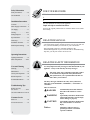
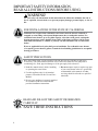
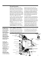
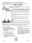
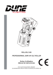
! Warning: This water heater is not
suitable for use in manufactured (mobile) homes!
Use & Care Manual
With Installation Instructions for the Installer
Residential Gas - FVIR Certified
Induced Draft Water Heaters
Residential 29 Gallon
The purpose of this manual is twofold: one, to provide the installer with the basic
directions and recommendations for the proper installation and adjustment of the water
heater; and two, for the owner–operator, to explain the features, operation, safety
precautions, maintenance and troubleshooting of the water heater. This manual also
includes a parts list.
It is very important that all persons who are expected to install, operate or adjust this
water heater read the instructions carefully so they may understand how to perform
these operations. If you do not understand these instructions or any terms within it, seek
professional assistance.
Any questions regarding the operation, maintenance, service or warranty of this water
heater should be directed to the seller from whom it was purchased. If additional
information is required, refer to the section on “If you need service.”
Do not destroy this manual. Please read carefully and keep in a safe place for
future reference.
Recognize this symbol as an indication of Important Safety Information!
!
!
!
California Proposition 65 Warning: This product contains chemicals known to
the State of California to cause cancer, birth defects or other reproductive harm.
ARNING: If the information in these instructions is not followed exactly,
W
a fire or explosion may result causing property damage, personal injury or death.
! FOR
YOUR SAFETY!
— Do not store or use gasoline or other
flammable vapors or liquids or other
combustible materials in the vicinity of this or
any other appliance. To do so may result in an
explosion or fire.
— WHAT TO DO IF YOU SMELL GAS
● Do not try to light any appliance.
● Do not touch any electrical switch; do not
use any phone in your building.
● Immediately call your gas supplier from a
neighbor’s phone. Follow the gas supplier’s
instructions.
● I f you cannot reach your gas supplier, call
the fire department.
●D
o not return to your home until authorized
by the gas supplier or fire department.
— Improper installation, adjustment, alteration,
service or maintenance can cause property
damage, personal injury, or death. Refer to
this manual. Installation and service must be
performed by a qualified installer, service
agency or the gas supplier.
DESIGN
Printed in USA
CER
TIFIED
®
AP15696 (11/10)
Safety Information
Safety Precautions. . . . . . . 3–6
FOR YOUR RECORDS
LP Gas Models . . . . . . . . . . . . 5
Write the model and serial numbers here:
#
Installation Instructions
Location. . . . . . . . . . . . . . . . . . 7
Water Supply Connections. . . 9
Gas Supply. . . . . . . . . . . . . . . 11
#
You can find them on a label on the appliance.
Staple sales slip or cancelled check here.
Proof of the original purchase date is needed to obtain service under
the warranty.
Venting. . . . . . . . . . . . . . . 12-13
Wiring Diagram. . . . . . . . . . . 14
Pipe Insulation. . . . . . . . . . . . 15
Heat Traps . . . . . . . . . . . . . . . 16
Installation Checklist. . . . . . . 17
Potable/Space Heating . . . . 18
READ THIS MANUAL
Inside you will find many helpful hints on how to use and maintain
your water heater properly. A little preventive care on your part can
save you time and money over the life of your water heater.
You’ll find many answers to common problems in the
Troubleshooting Guide. If you review the chart of Troubleshooting
Tips first, you may not need to call for service.
Operating Instructions
Lighting Instructions. . . . . . 19
Water Temperature . . . . . 20-21
Care and Cleaning
Draining. . . . . . . . . . . . . . . . 23
READ THE SAFETY INFORMATION
Your safety and the safety of others are very important. There
are many important safety messages in this manual and on your
appliance. Always read and obey all safety messages.
Maintenance. . . . . . . . . . . . . 23
!
Vent System Inspection. . . . 24
Burner Inspection . . . . . . . . 24
Extended Shut-Down. . . . . . 25
Troubleshooting Tips
Before You Call
For Service. . . . . . . . . . . . 26-27
Gas Valve LED Error Code. 28
Customer Service
Parts List. . . . . . . . . . . . . . . . 29
If You Need Service . . . . . . . 32
This is the safety alert symbol. Recognize this symbol
as an indication of Important Safety Information!
This symbol alerts you to potential hazards that can
kill or hurt you and others.
All safety messages will follow the safety alert symbol and
either the word “DANGER”, “WARNING”, “CAUTION” or
“NOTICE”.
These words mean:
An imminently hazardous situation ! DANGER
that will result in death or serious injury.
!
WARNING
!
CAUTION
Notice:
2
A potentially hazardous situation that could result in death or serious injury and/or damage to property.
A potentially hazardous situation that may result in minor or moderate injury.
Attention is called to observe a specified procedure or maintain a specific condition.
IMPORTANT SAFETY INFORMATION.
READ ALL INSTRUCTIONS BEFORE USING.
Be sure to read and understand the entire Use and Care Manual before attempting to install or operate this water
heater. It may save you time and money. Pay particular attention to the Safety Instructions. Failure to follow these
warnings could result in serious bodily injury or death. Should you have problems understanding the instructions in
this manual, or have any questions, STOP, and get help from a qualified service technician, or the local gas utility.
NOTICE: This water heater is equipped with a flammable vapor sensor that will automatically shut
down the water heater in the presence of gasoline vapors and some other flammable vapors. If the
flammable vapor sensor shuts down the water heater, contact a qualified service technician. Clear any
hazardous materials and ventilate the area around the water heater. Do not turn off the appliance
or adjust the ON/OFF switch in any way. Do not tamper with the flammable vapor sensor. Do not
submerse the flammable vapor sensor in water. Do not allow the flammable vapor sensor to come into
contact with any substances such as bleach or cleaners. See the “Gas Valve LED Error Code” Section
of this manual for a list of error codes.
DANGER!
properly vent the water heater
Failure to properly vent the water heater to the outdoors as outlined in the Venting Section
of the Installation Instructions in this manual can result in unsafe operation of the water
heater. To avoid the risk of fire, explosion, or asphyxiation from carbon monoxide, never
operate this water heater unless it is properly vented and has an adequate air supply for
proper operation. Be sure to inspect the vent system for proper installation at initial startup; and at least annually thereafter. Refer to the Care and Cleaning section of this manual
for more information regarding vent system inspection.
WARNING!
Gasoline, as well as other flammable materials and liquids (which include but are not
limited to adhesives, solvents, paint thinners etc.), and the vapors they produce are
extremely dangerous. DO NOT handle, use or store gasoline or other flammable or
combustible materials anywhere near or in the vicinity of a water heater or any other
appliance. Be sure to read and follow warning label pictured below and other labels on the
water heater, as well as the warnings printed in this manual. Failure to do so can result in
property damage, bodily injury or death.
!
FLAMMABLES
WARNING
Flammable Vapors
FIRE AND EXPLOSION HAZARD
!
Can result in serious injury or death.
Do not store or use gasoline or other flammable vapors and liquids
in the vicinity of this or any other appliance. Storage of or use of gasoline
or other flammable vapors or liquids in the vicinity of this or any other
appliance can result in serious injury or death.
3
IMPORTANT SAFETY INFORMATION.
READ ALL INSTRUCTIONS BEFORE USING.
! DANGER!
water temperature Setting
Safety and energy conservation are factors to be considered when selecting the water
temperature setting of a water heater’s gas control. Water temperatures above 125°F
can cause severe burns or death from scalding. Be sure to read and follow the warnings
outlined on the label pictured below. This label is also located on the water heater.
Time/Temperature Relationship in Scalds
Water Temperature
!
DANGER
120°F
125°F
130°F
135°F
140°F
145°F
150°F
155°F
Time To Produce a Serious Burn
More than 5 minutes
11/2 to 2 minutes
About 30 seconds
About 10 seconds
Less than 5 seconds
Less than 3 seconds
About 11/2 seconds
About 1 second
Table courtesy of Shriners Burn Institute
HOT
BURN
Water temperature over 125° F (52°C)
can cause severe burns
instantly or death from scalds.
Children, disabled and elderly are
at highest risk of being scalded.
See instruction manual before
setting temperature at water
heater.
Feel water before bathing or
showering.
Temperature limiting valves are
available, see manual.
Notice: Mixing valves are available for reducing point
of use water temperature by mixing hot and cold water
in branch water lines. Contact a licensed plumber or the
local plumbing authority for further information.
4
The chart shown above may be used as a guide in
determining the proper water temperature for your
home.
! DANGER: Households with small children,
disabled, or elderly persons may require a 120°F
or lower gas control (thermostat) setting to prevent
contact with “HOT” water.
Maximum water temperatures occur just after the
burner has shut off. To find water temperature being
delivered, turn on a hot water faucet and place
a thermometer in the water stream and read the
thermometer. (See page 20 and 21 for more details.)
The temperature of the water in the heater can be
regulated by rotating the dial on the front of the
gas control (thermostat). To comply with safety
regulations the gas control (thermostat) was set
at “HOT” position before the water heater was
shipped from the factory. The “HOT” dial position
corresponds to a water temperature of approximately
120°F. DANGER: Hotter water increases the
potential for Hot Water SCALDS. The illustration
below details the approximate water temperature
for each mark on the Gas Control (Thermostat)
Temperature Dial.
! DANGER: Hotter
water increases the
potential for Hot Water
SCALDS.
Valve Set
Point
LOW
●
●
●
HOT
A
B
C
VERY HOT
Estimated
Temperature
90°F
98°F
105°F
113°F
120°F
130°F
140°F
150°
160°F
Burns on Adult Skin
--------------------------------------------------------------------------------------------More than 5 minutes
About 30 seconds
Less than 5 seconds
About 1-1/2 seconds
About 1/2 second
DANGER!
liquefied petroleum (LP Propane or butane)
and Natural gas models
LP and Natural gas have an odorant added to aid in detecting a gas leak. Some people
may not physically be able to smell or recognize this odorant. If you are unsure or
unfamiliar with the smell of LP or natural gas, ask the gas supplier. Other conditions,
such as “odorant fade”, which causes the odorant to diminish in intensity, can also hide or
camouflage a gas leak.
● Water heaters utilizing LP gas are
different from natural gas models. A
natural gas water heater will not function
safely on LP gas and vice versa.
● No attempt should ever be made to
convert the water heater from natural
gas to LP gas. To avoid possible
equipment damage, personal injury or
fire, do not connect the water heater to a
fuel type not in accordance with the unit
data plate. LP for LP units. Natural gas
for natural gas units. These units are not
certified for any other fuel type.
● LP appliances should not be installed
below grade (for example, in a basement)
if such installation is prohibited by
federal, state and/or local laws, rules,
regulations or customs.
● LP gas must be used with great caution.
It is heavier than air and will collect first
in lower areas making it hard to detect at
nose level.
! DANGER: If a gas leak is present or
suspected:
● Do not attempt to find the cause
yourself.
● Do not try to light any appliance.
● Do not touch any electrical switch.
● Do not use any phone in your building.
● Leave the house immediately and make
sure your family and pets leave also.
● Leave the doors open for ventilation
and contact the gas supplier, a qualified
service agency or the fire department.
● Stay away from the house (or building)
until the service call has been made, the
leak is corrected and a qualified agency
has determined the area to be safe.
● Before attempting to light the water
heater, make sure to look and smell for
gas leaks. Use a soapy solution to check
all gas fittings and connections. Bubbling
at a connection indicates a leak that must
be corrected. When smelling to detect a
gas leak, be sure to sniff near the floor
also.
● Gas detectors are recommended in LP
& natural gas applications and their
installation should be in accordance
with the detector manufacturer’s
recommendations and/or local laws,
rules, regulations or customs.
● It is recommended that more than one
method, such as soapy solution, gas
detectors, etc., be used to detect leaks in
gas applications.
5
IMPORTANT SAFETY INFORMATION.
READ ALL INSTRUCTIONS BEFORE USING.
!
WARNING!
For your safety, the information in this manual must be followed to minimize the risk of
fire or explosion, electric shock, or to prevent property damage, personal injury, or loss of
life.
FOR INSTALLATIONS IN THE STATE OF CALIFORNIA
California Law requires that residential water heaters must be braced, anchored or
strapped to resist falling or horizontal displacement due to earthquake motions. For
residential water heaters up to 52-gallon capacity, a brochure with generic earthquake
bracing instructions can be obtained from: Office of the State Architect, 1102 Q Street,
Suite 5100, Sacramento, CA 95814 or you may call 916-445-8100 or ask a water heater
dealer.
However, applicable local codes shall govern installation. For residential water heaters
of a capacity greater than 52 gallons, consult the local building jurisdiction for acceptable
bracing procedures.
SAFETY PRECAUTIONS
Have the installer show you the location of the gas shut-off valve and how to shut it off
if necessary. Turn off the manual shut-off valve if the water heater has been subjected to
overheating, fire, flood, physical damage or if the gas supply fails to shut off.
● Read this manual entirely before installing
or operating the water heater.
● Use this appliance only for its intended
purpose as described in this Use and Care
Manual.
● Do not attempt to repair or replace any part
of your water heater unless it is specifically
recommended in this manual. All other
servicing should be referred to a qualified
technician.
● Be sure your appliance is properly installed
in accordance with local codes and the
provided installation instructions.
Read and follow this Safety Information
carefully.
SAVE THESE INSTRUCTIONS
6
Installing the water heater
This water heater must be installed in accordance with these instructions, local codes, utility company
requirements, and/or in the absence of local codes, use the latest edition of the American National
Standard/National Fuel Gas Code. A copy can be purchased from either the American Gas Association,
400 N. Capitol Street NW, Washington, DC 20001 as ANSI standard Z223.1 or National Fire Protection
Association, 1 Batterymarch Park, Quincy, MA 02269 as booklet NFPA 54.
Combustion Air Inlet
Openings
Max.
2.75”
Flammable
Vapor
Sensor
Location
The water heater should not be located
in an area where leakage from the tank
or connections will result in damage to
the area adjacent to the heater or to lower
floors of the structure.
When such areas cannot be avoided it is
recommended that a suitable catch pan,
adequately drained, must be installed
under the water heater.
Diameter of
water heater
plus 2” min.
The auxiliary catch pan
installation MUST conform
to local codes.
Notice: DO NOT allow the
catch pan to obstuct the
flammable vapor sensor.
Notice: DO NOT allow the
flammable vapor sensor to
become submerged in water.
Make sure the catch pan is
properly drained.
The water heater must be centered in the
catch pan.
The catch pan must not restrict air flow
to the combustion air inlet openings
(perforation openings) located around the
lower perimeter of the water heater.
Catch pan kits are available from the store
where the water heater was purchased, or
any water heater distributor.
Make certain the floor underneath the
water heater is strong enough to
sufficiently support the weight of the
water heater once it is filled with water.
A gas fired water heater or any other
appliance should not be installed
in a space where liquids which give off
flammable vapors are to be used or stored.
Such liquids include gasoline, LP gas
(butane or propane), paint or adhesives
and their thinners, solvents or removers.
DO NOT block or obstruct any of the
combustion air inlet openings located
around the perimeter of the water heater.
A minimum of 1” is required between
these combustion air inlet openings and
any obstruction.
! WARNING: Combustible
construction refers to
adjacent walls and ceilings
and should not be confused
with combustible or
flammable products and
materials. Combustible
and/or flammable products
and materials should never
be stored in the vicinity of
this or any gas appliance.
DO NOT obstruct or block the Flammable
Vapor Sensor.
Because of natural air movement in a
room or other enclosed space, flammable
vapors can be carried some distance from
where liquids which give off flammable
vapors are to be used or stored. The open
flame of the water heater’s pilot or main
burner can ignite these vapors and create
a shut down condition of the water heater
which will not allow the water heater
to ignite until examined by a Qualified
Service Technician.
Rheem Water Heating FVIR certified
gas water heaters can be installed on
a residential garage floor without the
use of an 18" stand in accordance with
the National Fuel Gas Code, NFPA 54,
ANSI Z223.1 2006, paragraph 9.1.10
Installation in Residential Garages, unless
otherwise directed by State and Local
code requirements. The water heater must
be located so it is not subject to physical
damage, for example, by moving vehicles,
area flooding etc.
● Hot water lines should be insulated to
conserve water and energy.
● The water heater and water lines should
be protected from exposure
to freezing temperatures.
● Do not install the water heater in
bathrooms, bedrooms, any occupied
rooms normally kept closed, or in
unprotected outdoor areas.
● Minimum clearance from combustible
construction:
Closet &
Alcove
Front
Side
Rear
Top
3”
(7.6 cm)
1”
(2.5 cm)
0”
(0 cm)
12”
(30.5 cm)
If the clearances stated on the
Instruction/Warning Label, located on
the front of the heater differ, install the
water heater according to the clearances
stated on the label.
● If the water heater is installed in an
alcove or closet, the entire floor must
be covered by a wood or metal panel.
A minimum of 24” clearance from the
front and top should be available for
adequate inspection and servicing.
● The water heater may be installed on
combustible floors, but not directly on
carpeting. If the water heater must be
installed on carpeting, place a metal or
wood panel beneath the water heater,
extending beyond its full width and
depth at least 3” in all directions.
7
Installing the water heater
Inspect Shipment
Inspect the water heater for possible damage. Check the markings on the rating plate of
the water heater to be certain the type of gas supplied corresponds to the water heater
requirements.
Combustion and Ventilation Air
Proper operation of the water heater
requires air for combustion and
ventilation. Provisions for combustion
and ventilation air must comply with
referenced codes and standards.
DO NOT block or obstruct any of the
combustion air inlet openings located
around the perimeter of the water
heater. A minimum of 1” is required
between these combustion air inlet
openings and any obstruction.
NOTICE: If the water heater is
installed in an unconfined space within a
building of conventional frame, masonry
or metal construction, infiltration
air is normally adequate for proper
combustion and ventilation. If the
water heater is installed in a confined
space, provisions for combustion and
ventilation air must be made.
DO NOT obstruct or block the Flammable
Vapor Sensor.
A confined space is one having a volume
of less than 50 cubic feet per 1000 Btuh
of the aggregate input of all appliances
within that space.
The air must be supplied through two
permanent openings of equal area. One
is to be located within 12” above the floor
and the other is to be located within 12”
from the ceiling.
NOTICE: The water heater
should not be installed near
an air supply containing
halogenated hydrocarbons.
8
The minimum net free area of each opening
must not be less than one square inch
per 1000 Btuh of the total input rating
of all the appliances in the enclosure
(but not less than 100 square inches), if
each opening communicates with other
unconfined areas inside the building.
Buildings of unusually tight construction
shall have the combustion and ventilation
air supplied from outdoors, or a freely
ventilated attic or crawl space.
If air is supplied from outdoors, directly or
through vertical ducts, there must be two
openings located as specified above and
each must have a minimum net free area
of not less than one square inch per 4000
Btuh of the total input rating of all the
appliances in the enclosure.
If horizontal ducts are used to
communicate with the outdoors, each
opening must have a minimum net free
area of not less than one square inch per
2000 Btuh of the total input rating of all
the appliances in the enclosure. If ducts
are used, the minimum dimensions of
rectangular air ducts shall not be less than
3”.
NOTICE: If the duct openings which
supply combustion and ventilation air
are to be covered with a protective
screen or grill, the net free area
(openings in the material) of the
covering material must be used in
determining the size of the openings.
Protective screening for the openings
MUST NOT be smaller than 1/4”mesh
to prevent clogging by lint or other
debris.
Corrosive Atmospheres
The air in beauty shops, dry cleaning
establishments, photo processing
labs, and storage areas for liquid and
powdered bleaches or swimming pool
chemicals often contain such halogenated
hydrocarbons.
An air supply containing halogenated
hydrocarbons may be safe to breathe,
but when it passes through a gas flame
corrosive elements are released that
will shorten the life of any gas burning
appliance.
Propellants from common spray cans
or gas leaks from A/C and refrigeration
equipment are highly corrosive after
passing through a flame.
The water heater warranty is voided when
failure of the heater is due to operation in
a corrosive atmosphere.
Thermal Expansion
Determine if a check valve exists in the
inlet water line. Check with your local water
utility company. It may have been installed
in the cold water line as a separate back flow
preventer, or it may be part of a pressure
reducing valve, water meter or water softener.
A check valve located in the cold water inlet
line can cause what is referred to as a “closed
water system”. A cold water inlet line with no
check valve or back flow prevention device is
referred to as an “open” water system.
As water is heated, it expands in volume and
creates an increase in the pressure within the
water system. This action is referred to as
“thermal expansion”. In an “open” water
system, expanding water which exceeds the
capacity of the water heater flows back into
the city main where the pressure is easily
dissipated.
A “closed water system”, however, prevents
the expanding water from flowing back
into the main supply line, and the result of
“thermal expansion” can create a rapid and
IMPORTANT: Do
not apply heat to
the HOT or COLD
water connections.
If sweat connections
are used, sweat
tubing to adapter
before fitting adapter
to the cold water
connections on
heater. Any heat
applied to the cold
water supply fittings
will permanently
damage the dip tube
and heat traps.
NOTICE: The
National Fuel Gas
Code (NFGC)
mandates a manual
gas shut-off valve:
See (NFGC) for
complete instructions.
Local codes or
plumbing authority
requirements may
vary from the
instructions or
diagrams provided
and take precedent
over these instructions.
dangerous pressure increase in the water
heater and system piping. This rapid pressure
increase can quickly reach the safety setting
of the relief valve, causing it to operate during
each heating cycle. Thermal expansion, and
the resulting rapid, and repeated expansion
and contraction of components in the water
heater and piping system can cause premature
failure of the relief valve, and possibly the
heater itself. Replacing the relief valve will
not correct the problem!
The suggested method of controlling thermal
expansion is to install an expansion tank in the
cold water line between the water heater and
the check valve (see illustration below). The
expansion tank is designed with an air cushion
built in that compresses as the system pressure
increases, thereby relieving the over pressure
condition and eliminating the repeated
operation of the relief valve. Other methods
of controlling thermal expansion are also
available. Contact your installing contractor,
water supplier or plumbing inspector for
additional information regarding this subject.
Water Supply Connections
Refer to the illustration below for suggested
typical installation. The installation of unions
or flexible copper connectors is recommended
on the hot and cold water connections so that
the water heater may be easily disconnected
Typical Installation
Heat trap
6” minimum
Hot water outlet to
fixtures
for servicing if necessary. The HOT and COLD
water connections are clearly marked and are
3/4” NPT on all models. Install a shut-off valve
in the cold water line near the water heater.
Union
Vacuum Relief Valve
(Not Supplied)
Union
Water Heater Jacket
Temperature and
pressure relief valve
Manual gas shut-off
Shut-off
valve
To gas supply
Heat trap
6” minimum
To cold water
supply
Ground joint union
Thermal expansion
tank (if required)
Sediment trap
Cap
Combustion Air
Inlet Openings
Jacket door
Flammable Vapor Sensor
Auxiliary catch pan
Shut-off valve
Relief valve discharge
line to suitable open
drain.
Drain
valve
Thermostatic gas valve
If required, install per local codes
and valve manufacturer’s
instructions.
Drain Pan Pipe
to suitable drain.
6” Air gap
9
Installing the water heater
A new combination temperature and pressure relief valve, complying with the Standard for Relief Valves
and Automatic Gas Shut-Off Devices for Hot Water Supply Systems, ANSI Z21.22, is supplied and must
remain in the opening provided and marked for the purpose on the water heater. No valve of any type
should be installed between the relief valve and the tank. Local codes shall govern the installation of
relief valves.
Relief Valve
The pressure rating of the relief valve
must not exceed 150 PSI, the maximum
working pressure of the water heater as
marked on the rating plate.
The Btuh rating of the relief valve must
equal or exceed the Btuh input of the
water heater as marked on its rating plate.
Position the outlet of the relief valve
above a suitable open drain to eliminate
potential water damage. Piping used
should be of a type approved for hot water
distribution.
WARNING: The tank
must be full of water before
heater is turned on. The
water heater warranty does
not cover damage or failure
resulting from operation
with an empty or partially
empty tank.
The discharge line must be no smaller
than the outlet of the valve and must
pitch downward from the valve to allow
complete drainage (by gravity) of the
relief valve and discharge line.
The end of the discharge line should not
be threaded or concealed and should be
protected from freezing. No valve of
any type, restriction, or reducer coupling
should be installed in the discharge line.
To Fill the Water Heater
Make certain that the drain valve is
closed, then open the shut-off valve in the
cold water supply line.
Open each hot water faucet slowly to
allow the air to vent from the water
heater and piping.
A steady flow of water from the hot water
faucet(s) indicates a full water heater.
Do not allow the flammable vapor sensor
to become submerged in water.
Condensation
Condensation can form on the tank
when it is first filled with water.
Condensation might also occur with a
heavy water draw and very cold inlet
water temperatures.
Drops of water falling on the burner can
produce a sizzling or pinging sound.
10
This condition is not unusual, and will
disappear after the water becomes heated.
If, however, the condensation continues,
examine the piping and fittings for
possible leaks.
WARNING: Do not attempt to convert this water heater for use with a different type of gas other than the type
shown on the rating plate. Such conversion could result in hazardous operating conditions.
Gas Supply
The branch gas supply line to the water
heater should be clean 1/2” black steel
pipe no more than 40 equivalent feet long
or other approved gas piping material.
A ground joint union or ANSI design
certified semi-rigid or flexible gas
appliance connector should be installed
in the gas line close to the water heater.
The National Fuel Gas Code (NFGC)
mandates a manual gas shut-off valve: See
(NFGC) for complete instructions.
If flexible connectors are used, the
maximum length shall not exceed 36”
and must meet the requirements in ANSI
Z21.24-Connectors for Gas Appliances.
If lever type gas shut-offs are used,
they shall be T-Handle type.
Compound used on the threaded joints of
the gas piping must be of the type resistant
to the action of LP gas. Use compound
sparingly on male threads only.
Where a sediment trap is not incorporated
as part of the appliance, a sediment trap
shall be installed downstream of the
equipment shutoff valve as close to the
inlet of the appliance as practical at the
time of the appliance installation. The
sediment trap shall be either a tee fitting
with a capped nipple in the bottom outlet
or other device recognized as an effective
sediment trap.
Do not use excessive force (over 31.5 ft
lbs.) in tightening the pipe joint at the gas
control (thermostat) inlet, particularly if
teflon pipe compound is used, as the valve
body may be damaged.
The inlet gas pressure to the water heater
must not exceed 10.5” w.c. for natural gas,
or 14” w.c. for LP gas. For purposes of
input adjustment, the minimum inlet gas
pressure (with main burner on) is shown
on the water heater rating plate. If high or
low gas pressures are present, contact your
gas supplier for correction.
Leak Testing
WARNING:
Never use an open
flame to test for gas
leaks, as property
damage, personal
injury, or death
could result.
The water heater and its gas connections must
be leak tested at normal operating pressures
before it is placed in operation.
The factory connections to the gas control
(thermostat) should also be leak tested after
the water heater is placed in operation.
urn on the manual gas shut-off valve
T
near the water heater.
se a soapy water solution to test for
U
leaks at all connections and fittings.
Bubbles indicate a gas leak that must be
corrected.
Pressure Testing the Gas Supply System
The water heater and its manual gas shutoff valve must be disconnected from the gas
supply piping system during any pressure
testing of that system at
pressures in excess of 3/8 psi (10.5” w.c.) for
natural gas, or 1/2 psi (14” w.c.) for LP gas.
The water heater must be isolated from the
gas piping system by closing the manual gas
shut-off valve during any pressure testing of
the gas supply piping at pressures equal to or
less than
3/8 psi (10.5” w.c.) for natural gas, or
1/2 psi (14” w.c.) for LP gas.
11
Installing the water heater
! WARNING: Failure
to install a water heater
suitable for the altitude at
the location it is intended
to serve, can result in
improper operation of
the appliance resulting
in property da