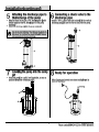
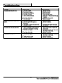
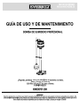
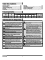
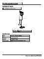
1
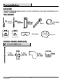
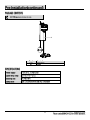
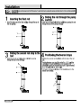
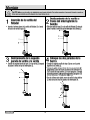
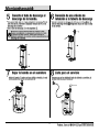
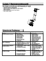
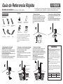
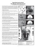
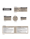
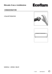
70*17mm logo 60*35mm SKU 1001 093 963 Model SCN250-LQ Pedestal Sump Pump Bomba De Sumidero De Pedestal 115V 60Hz 1/3HP 4.0Amps THERMALLY PROTECTED PROTECCIÓN TÉRMICA Serial No./Serial No.: 000000 Date Code/Código de Fecha: 1439 name plate 210*55mm WARNING ADVERTENCIA • Connect the pump DIRECTLY to a properly grounded, 115V GFCI outlet and never use an extension cord to power this pump • Pull plug before servicing this pump • This pump has not been tested or approved for use in swimming pools or in salt-water marine areas • Do not pump flammable or explosive liquids, pump water only with this pump • To reduce risk of electrical shock, fully read, follow and save the operating and installation instructions before attempting to install or operate this pump • Do not run this pump dry • NOTICE: Do not handle pump with wet hands or when standing on a wet surface, or in water MADE IN CHINA cord tag • Conecte la bomba DIRECTAMENTE a una toma de tierra, nunca utilice un cable de extensión para proporcionar alimentación a la bomba • Desconecte la bomba antes de cualquier clase de mantenimiento • Esta bomba no se ha puesto a prueba y no ha sido aprobada para uso en piscinas o en áreas de agua salada • No bombee líquidos inflamables o explosivos, bombee solamente agua con esta bomba • Para reducir el riesgo de descarga eléctrica, lea totalmente, siga y guarde las instrucciones de uso e instalación antes de intentar instalar o utilizar la bomba • No haga funcionar esta bomba en seco • AVISO: No maneje la bomba con las manos mojadas o estando en agua o en la superficie mojada HECHO EN CHINA ° : : : l Quick Start Guide Read your manual for installation, operation, and safety information. This guide neither supplements nor replaces the Owner’s Manual. Pedestal Sump Pump (Pump pictured is typical) Materials: YOU WILL NEED: 1. Sump Requirements Pit must be covered. It is usually 12’’ in diameter and 18’’ deep. See pump owner’s manual for pit size needed. Install on a hard surface: brick, cement, or concrete block; no sand, clay, or gravel. Tools: Threaded Adapter (Pipe to Pump) Screw Driver Hacksaw 2.Inserting The Float Rod Insert the plain end of the float rod (1) up through the eye of the rod guide. Slide one rod stop (2) on the float rod (1) before passing the rod through the eye of the pump switch (3). 1-1/4’’ or 1-1/2’’ ABS or PVC Pipe Channel Locks PVC 1-1/4’’ or 1-1/2’’ Check Valve Pipe wrench Tape Measure 3. Sliding The Second Rod Stop To The Rod Cable Ties Slide the second rod stop (4) on the rod (1) after passing through the eye of the switch (3). Position the two rod stops: A. Position the second rod stop (4) flush with the top of the rod (1). B. Position the lower rod stop (2) to within 7 in. (17.8 cm) of switch lever arm (3). 3 ABS or PVC Cement (to match the pipe) Unless otherwise noted, models with a tethered float switch require a sump pit at least 14’’ in diameter. Models with a vertical float switch require a sump pit at least 10’’ in diameter. 2 12’’ diameter 1 18’’depth Sump Pit 4. Installing The Discharge Plumbing 5. Inserting The Pump Install the discharge plumbing and check valve on the pump: A. Use Teflon tape-NOT pipe joint compound. B. Tighten the pipe into the pump. C. Install the check valve as close to the pump as possible. D. Drill an 1/8” anti-airlock hole as shown. The hole must be in the sump. Place the pump in the sump; make sure that nothing interferes with switch operation. Check the pump’s operation by filling the sump with water until the pump starts. Let it run until it has pumped down the sump and stopped. Plug the pump into a 15-amp circuit. The circuit should be GFCI protected and dedicated to the sump pump. WARNING: WARNING: Plastic pipe glue is extremely flammable. Follow the glue manufacturer’s instructions carefully if you are using glued plastic pipe for the discharge pipe. Install in compliance with all applicable laws, codes, and ordinances. Non-compliance may cause product failure, property damage, and/or personal injury. The pump should start and stop at the water levels shown below. See your pump owner’s manual to determine the pumping range for your pump. 7 in. 4 3 Check Valve 1-1/4” or 1-1/2” Discharge Pipe Do not use an extension cord with a sump pump. Regularly inspect pump inlet and clean away any debris. Switch Setting in Inches (mm) 2 SNC250 1 PVC Threaded Adaptor ON OFF 10’’(254) 3’’(76) Guía de Referencia Rápida Bomba de sumidero (La bomba que se ilustra es típica) Materiales: SE NECESITARÁ: Herramientas: Adaptador fileteado (Tubo a Bomaba) Destornillador Sierra de acro Tubo de ABS o de PVC de 1-1/4” ó de 1-1/2” Es importante leer el manual para obtener información sobre la instalación, la operación y la seguridad.Esta guía no complementa ni reemplaza al Manual del Propietario. 1. Requisitos Sump 2. Inserción La Varilla Del Flotador Pit debe estar cubierto. Por lo general es de 12'' de diámetro y 18'pies de profundidad. Consulte el manual del propietario de la bomba para el pozo de tamaño necesario. Instalar en una superficie dura: ladrillo, cemento o bloques de concreto; hay arena, arcilla o grava. Inserte el extremo plano de la varilla del flotador (1) a través del ojo de la guía de la varilla. Deslice un tope de la varilla (2) en la varilla del flotador (1) antes de pasar la varilla a través del ojo del interruptor de la bomba (3). Pinzas ajustables a cremallera PVC 1-1/4'' o 1-1/2'' Válvula de Retención Llave para tubos Cinta métrica Bridas 3. Deslizamiento De La Parada Segunda Varilla A La Varilla Deslizar el segundo tope de la varilla (4) sobre la varilla (1) después de pasar a través del ojo del interruptor (3). Coloque las dos paradas de la barra: A. Posición del segundo tope de la varilla (4) a ras con la parte superior de la varilla (1). B. Colocar la varilla de tope inferior (2) dentro de 7 pulg. (17,8 cm) de brazo de palanca del interruptor (3). 7 in. 4 3 3 Cemento ABS o PVC (según el tubo) A menos que se haya indicado lo contrario, los modelos con un interruptor de flotador anclado requieren un pozo de recogida con un diàmetro mínimo de 14”. Los Modelos con un interruptor de flotador vertical requieren un foso de recogida de por lo menos 10” de diàmetro. 1 18’’depth Sump Pit 4. Instalación de la tubería de descarga 5. Inserción La Bomba Instale la tubería de descarga y la válvula de la bomba: A. Use cinta de teflón-NO pasta de juntas. B. Apriete el tubo en la bomba. C. Instale la válvula de retención como cerca de la bomba como posible. D. perforar un agujero de 1/8" anti-esclusa de aire como se muestra. El agujero debe estar en el sumidero. Coloque la bomba en el sumidero; asegurarse de que nada interfiere con la operación del interruptor. Compruebe el funcionamiento de la bomba, llenando el sumidero con agua hasta que la bomba arranque. Deje que se ejecute hasta que haya bombeado por el sumidero y se detuvo. Conecte la bomba a un circuito de 15 amperios. El circuito debe estar protegido GFCI y dedicada a la bomba de sumidero. Válvula de retención Tubería de descarga de 1-1/4” ó de 1-1/2” 2 12’’ diameter ADVERTENCIA: ADVERTENCIA: EI pegamento para tuberías de plástic es extremadanente inflammable. Siga las instrucciones del fabricante del pegamento con atención si La instalación se debe realizer conforme a todas las leyes,los códigos y las normas correspondientes. Si se hace caso omiso a estas disposiciones,existe el peligor de que el product falle, y ocurran danos materiales y/o lesions personales. No use un cordón de alargue con una bomba de sumidero. Inspeccione la admisión de la bomba con regularidad y limpie la suciedad que se haya acumulado. La bomba se debe encender y apagar a los niveles de agua que aparecen a continuación, Consulte su manual de propietario de la bomba para determinar la gama de bombeo para su boma. Ajuste del interruptor en pulgadas(mm) 2 1 SNC250 Adaptador roscado PVC Sí No 10’’(254) 3’’(76) Let Us Help You ! Permítanos Help ! Do not return your product to the store. Call us first! If you have questions regarding your product or require warranty assistance, please call our customer service toll-free helpline No devuelva su proudct a la tienda. Llámenos primero! Si tiene alguna pregunta con respecto a su producto o si necesita asistencia con la garantía, por favor llame a nuestra línea de ayuda de servicio al cliente de gratis 1-844-241-5521 Contact us for assistance, we're here to help. En contacto con nosotros para obtener ayuda, estamos aquí para ayudar.