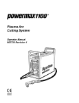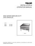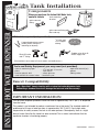
1
Tank Installation
Components
When you purchase the Instant Hot Water tank,
tank mounting
contents include:
bracket
INSTANT HOT WATER DISPENSER
quick-connect
fitting
tank
quick-connect fitting with
filter and cap
Materials required (not provided)
2 mounting bracket screws
(and 2 plastic anchors if
attaching to drywall)
1/4"
(6.4 mm)
O.D. copper
tubing.
Saddle valve kit to fit
water supply line.
Shut-Off valve
and “T” fitting
(Connections must meet all local codes and ordinances.)
Tools and Safety Equipment you may need (not provided)
• ruler or measuring tape
• pliers
• hand or electric drill
• small drill bit for starter holes
• 13/8" drill bit - if no sink
hole exists
• safety glasses
• bucket or pan
• open-end wrench(es)
• gloves
• tubing cutter
Faucet Compatibility
Only “Open Vent” faucets function with a instant hot water dispenser tank.
Connecting a standard faucet will damage the tank and void the warranty.
IMPORTANT INFORMATION
This hot water dispenser produces instant hot water of approximately 190°F (88°C) as dispensed
from the faucet.
This product is not intended to produce a continuous flow of hot water. The standard model will
produce up to 60 cups of water per hour at approximately 190°F (88°C). Due to high water
temperature, for safety reasons, the tank is not under pressure. Consequently, there is a slight
delay of water flow after the faucet has been activated. This is normal and indicates that the
expansion chamber is functioning properly.
560H486P01 REV G
IMPORTANT SAFETY INSTRUCTIONS
PLEASE READ ALL INSTRUCTIONS VERY CAREFULLY
When using electrical appliances, basic safety precautions should always be followed including the following:
1. Read all instructions.
2. To protect against electrical shock, do not place cord, plugs, or appliance in water or other liquid.
3. Do not operate any appliance with a damaged cord or plug, or after the appliance malfunctions.
Return appliance to the factory for examination, repair or adjustment. See Warranty insert.
4. Do not use outdoors or in damp area.
5. Do not let cord hang over edge of table or counter, or touch hot surfaces.
6. Do not use appliance for other than intended household use.
7. When using this appliance, provide 4 to 6 inches of air space around the entire unit for air circulation.
8. Do not attempt to service this product. Repairs should be done by authorized service personnel.
9. Do not let children operate. The water can cause severe burns.
SAVE THESE INSTRUCTIONS. THIS PRODUCT FOR HOUSEHOLD USE ONLY.
The alert symbols displayed at right point to important safety
information to make you aware of potential hazards that can
cause serious injury or death. Please pay special attention to
the information following these alerts and warnings. Failure to
comply with these instructions can result in property damage,
serious injury or death.
WARNING
DANGER
ELECTRICAL REQUIREMENTS
Recommended Ground Method
For your personal safety, the hot water dispenser is equipped with a power supply cord having a 3-prong
ground plug. To minimize possible shock hazard, the cord must be plugged into a mating 3-prong, ground-type
outlet, grounded in accordance with the National Electrical Code, ANSI/NFPA 70 — latest edition* or CSA
Standard C22.1, Canadian Electrical Code, Part 1, — latest edition** and all local codes and ordinances.
If a mating outlet is not available, it is the personal responsibility and
obligation of the customer to have a properly grounded, 3-prong outlet
installed by a qualified electrician.
Copies of the standards listed may be obtained from:
* National Fire Protection Association
One Batterymarch Park
Quincy, MA 02269
**CSA International
178 Rexdale Boulevard
Toronto, Ontario M9W1R3
If codes permit and a separate ground wire is used, it is recommended
that a qualified electrician determine that the ground path is adequate.
A 120 volt, 60 Hz, AC only 15 or 20 ampere fused, grounded electrical
supply is required. It is recommended that a separate circuit serving only
your hot water dispenser be provided.
NOTE: Use an outlet that cannot be turned on/off by a switch.
WARNING
Electrical Shock
Hazard
Plug into a grounded
3 prong outlet.
Do not remove ground
prong.
Do not use an adapter.
Do not use an extension
cord.
Failure to follow these
instructions can result in
death, fire or electrical
shock.
HOT WATER CONCEPT
Unlike a household water heater, this dispenser tank is not pressurized for safety reasons. For a conventional
household water heater, the faucet valve is placed after the heater tank resulting in a pressurized tank. For a
hot water dispenser, the faucet valve is placed before the tank, creating an “open vent” style faucet and
consequently no pressure is built up inside the tank.
OVERVIEW
1. Make sure you have all necessary parts, tools and materials as suggested on manual cover.
2. Determine a convenient location to mount your faucet. This can be an existing sink hole in the sink
top (the spray hose opening for example) or you may drill another hole into the sink or counter-top. As
you determine the location of your faucet, consider the container you will use with the appliance, such
as a large cooking pan. Location of the hole should also provide easy access for tank connections.
3. The thickness of the sink or counter will depend on the type of faucet being installed.
• For Tahoe and Laguna Series (H510 & H520) 2.00” max.
• For Sonoma and Sierra Series (H610 & D620) 2.60” max.
• For Coronado and Madera Series (H710 & D720) 3.00” max.
4. Before connecting to the power source, the dispenser must be filled with water and the thermostat
turned to the OFF position.
5. Do not use an extension cord with this appliance. Appliance must be within 36” (914mm) of the
power source. See electrical requirements.
6. Plumbing connections must comply with all local codes and ordinances.
7. Do not use any pipe sealing compounds as they may get inside the dispenser causing an
objectionable taste and odor.
Important: Observe all governing codes and ordinances.
Faucet may be installed in spray hose opening in sink or drilled
hole. If faucet is not to be installed in sink spray hose opening,
cut 11/4” (32mm) min. — 13/8” (35mm) max. dia. hole.
Quick-connect fitting with filter
and cap connects to cold water
supply line. Filter and cap side
points toward faucet.
111/8”
(283 mm)
42” (1067 mm) max. —
electrical outlet to tank
Connector and section of 1/ 4” (6.4
mm) copper tubing are not provided
(saddle valve shown).
See step 4 of installation for optional
connections and instructions.
8 1/ 16”
(205 mm)
6 13/ 16”
(173 mm)
Tank
must be
mounted
vertically
INSTALLATION
Before You Begin
Determine where you will install your hot water dispenser. The faucet can be mounted in an existing hole
in the sink (spray hose, etc.), or drill a 11/16” (27 mm) to 13/8” (35 mm) hole in your sink. If you want to
use the spray unit or do not have a hole in your sink you will have to drill a new hole.
Stainless Steel: You need a 11/16” (27 mm) to 13/8” (35 mm) knockout punch available at most hardware
stores or drill a hole with an expandable drill.
Porcelain: Proper tools are required to drill through a porcelain or cast iron sink. If you are not familiar with
this process you should consider having this done by a professional plumber.
Do not attempt to drill without these special tools as you may severely damage your sink.
BE SURE TO CONFIRM YOUR FAUCET’S COMPATIBILITY WITH THIS APPLIANCE.
FAUCET MUST BE “OPEN VENT” STYLE.
Step 1 - Mounting Tank
Position tank vertically beneath faucet so the flexible
tube from the faucet reaches the center faucet supply
tube on the tank and tank touches the wall. Mark the
wall at the top of tank. Set tank aside. Mark a second
line 21/8” (54 mm) below the first line. Align bottom of
bracket even with the second line and screw into
place. If a stud is not available, drywall anchors may
be used for additional support. Hang tank on bracket.
(2 1/8”)
54mm
bracket
be sure
dial is in
position
during
installation
OFF
NOTE: The tank must be positioned so the hose to the faucet does not twist or kink.
Step 2 - Install Faucet
Follow the instructions included with faucet.
Step 3 - Connect Faucet to Tank
Connect 1/4” (6.4 mm) faucet copper line (longer piece) or red line to the rear tube at the top corner of the
tank with the quick-connect fitting supplied with the appliance. (Do not use the quick-connect fitting with
filter and cap.) Push line straight into quick-connect fitting as far as possible for both connections.
Use pliers to open clamp and thread hose through clamp then push fully onto center inlet tube on top of
tank. The clamp should create a secure connection when properly installed.
Be sure the hose is not twisted or kinked. Hose may be shortened if necessary.
NOTE: DO NOT lengthen the hose – dispenser performance will be impaired and warranty will be void.
quick-connect fitting with filter and cap connects to cold
water line and contains a filter inside fitting. It also has
a cap at one end.
faucet line connects to
the inlet tube located on
top corner of tank with
quick-connect fitting
(supplied with tank).
cap
filter
faucet line connects to
cold water supply.
quick-connect
clamp
hose connects with
clamp to faucet supply
tube at center of tank.
center inlet tube
Step 4 - Connect Cold Water Supply
Check Filter in Quick-Connect Fitting
The cone-shaped screen filter comes seated inside the quick-connect fitting with the narrow end pointing
towards the cap which is also attached to the fitting. (The open or wide end of the screen is inserted into
the fitting.) However, the filter may become dislodged in the shipping process. Check to see that it is
seated correctly within the fitting. If the cap is still in place, pop cap off by slipping a screwdriver into the
notch and lift off. Gently pull on the screen. If it comes loose, push in with a light jiggling or wiggling
motion until it snaps into place. If installed properly, a gentle pull should not dislodge it.
Refer to installation instructions included with faucet if necessary.
Cold water is supplied to the tank through the faucet. Connect the cold water line to the faucet using the
1/4” (6.4 mm) supply line and the quick-connect fitting that contains a cone shaped screen filter (supplied
with the tank.) The cap end of the fitting connects to the faucet line.
It is suggested that a shut-off valve be installed between this connection and the cold water supply line.
Another common installation method is with the use of a saddle valve illustrated below. If a saddle valve
is used, follow the manufacturer’s installation instructions.
faucet
faucet line
to tank
faucet line to
cold water
supply
TYPICAL INSTALLATIONS
shut-off valve
“T” connection with
Shut-Off Valve
Installation
“T” connector
hose to tank
quick-connect with filter and cap
cold water supply
faucet
faucet line
to tank
hose to tank
faucet line to
cold water
supply
quick-connect with filter and cap
Saddle Valve
Installation
saddle valve
Step 5 - Check for Leaks
Open valve in water line. Turn faucet on (hold if
necessary) to fill tank (about 1 minute). When tank is
full, water will flow from faucet. Turn faucet off. Check
for leaks.
open
Step 6 - Prepare for Power
Double check thermostat control dial is in the
OFF position. Thermostat control dial controls the
water temperature, not the water flow or
delivery.
place bucket under valve in case
of of any leaking
IMPORTANT INFORMATION - This dispenser is equipped with a Self Re-setting Thermal Fuse
Turn thermostat to OFF position and fill tank with water before plugging the power cord from the
tank into an electrical outlet
If tank is empty and the thermostat set in the ON position when the power cord is connected, the
self re-setting fuse in the heater control will disconnect the current to the heater after approximately
one minute, thus protecting the heater from a "dry start” failure. The fuse in the heater control will
self-reset after approximately 1/2 hour*. Turn on the water supply to the tank and continue the
installation.
Continued misuse will cause damage to the appliance and is detectible thus, voiding the warranty.
*(Re-setting of fuse can be accelerated by turning on the water supply and dispensing water until
use re-sets, approximately 3 minutes.)
Step 7 - Test Installation
Plug electrical cord into a grounded 3-prong outlet.
Do not use an outlet controlled by an off/on wall switch. Turn thermostat control dial clockwise to the
highest position. Maximum temperature will be reached in about 15 minutes and dispenser will be ready
for use. Lower the temperature setting by turning thermostat control dial counterclockwise if you notice
vapor or a boiling noise. To raise or lower the water temperature, rotate the thermostat dial. At the LOW
setting of thermostat dial water temperature will be approximately 140°F (60°C) and at the HIGH setting
of the thermostat dial water temperature will be approximately 200°F (93°C).
CLEANING AND MAINTENANCE
Seasonal Shutdown
To prevent damage when dispenser is exposed to freezing
temperatures, water must be drained.
1. Unplug dispenser tank to power supply.
O-ring
screw
2. Turn thermostat control dial to OFF position (fully
counterclockwise).
3. Turn faucet on and run water until water is cold.
4. Place a 3-quart (2.8 L) container under drain plug at bottom
of the tank. Use a screwdriver to remove the screw and
O-ring in the drain tube opening. When tank is fully drained
replace O-ring and screw. Tighten to reseal the drain.
NOTE: Do not plug appliance into power supply if tank is empty.
Cleaning Quick-Connect Filter Screen at Cold Water Inlet
If you notice that the water flow is reduced, it may be necessary to clean the quick-connect screen. Refer to
Installation Step 4.
1. Turn thermostat dial to the “Off” position. Turn on
faucet and run water until it is cold to avoid possibility
of burn.
Quick-connect with filter and cap
cap
2. Release cap with a screwdriver, pry it loose using the
notch in the cap.
3. Also using the screwdriver push in on the smallest
ring around copper line. This action releases tension,
allowing disconnection of the copper line and quickconnect.
notch
filter screen
4. Pull cone shaped filter screen out (there will be slight
tension) and clean with vinegar as necessary. Check cap and clean as necessary. If deposits have
hardened, soak in vinegar for an hour or two. Then use a brush to clean.
5. Reassemble in reverse order of disassembly. Be aware, when inserting the screen back into place there is
a slight resistance. Push until the screen “pops” into place. Check for leaks.
6. Turn thermostat dial to the “Max” setting. The dispenser will be ready in about 15 minutes.
TROUBLESHOOTING
The following situations are not covered by the One Year Replacement Warranty.
1. Water is not hot: (assuming cold water supply is connected properly and valve is open)
• Check if dispenser is plugged in.
• Turn thermostat control dial fully clockwise. This may produce boiling water in approximately
15 minutes and possibly be accompanied by a gurgling sound in the tank and/or water “sputtering”
from the faucet.
If the water boils, turn thermostat control dial slightly counterclockwise until the gurgling and/or
“sputtering” stops. This should take place within 20 seconds. Turn control dial an additional 1/8” (3mm)
counterclockwise at the tip of the dial. Wait 15 minutes and check the temperature of the water.
• Check for blown fuse or circuit breaker is tripped (also see IMPORTANT NOTE explaining the
self re-setting thermal fuse in step 6 of installation).
NOTE: The thermostat activates the heater after water temperature in the tank drops approximately
15°F (8°C) from the maximum setting. The dispenser does not produce a continuous flow of hot water.
2. Hot water drips or sputters from faucet:
• Turn thermostat control dial counterclockwise (see item 1).
• Check that the hose connecting the faucet to the dispenser tank is not clogged, twisted or kinked.
• If quick-connect fitting is connecting cold water supply, check for a clogged filter screen in
quick-connect fitting (see CLEANING AND MAINTENANCE of faucet manual).
• Check for proper installation of copper tubing from faucet to dispenser tank and faucet to water line.
If connected backwards or cross-connected, valve may be damaged. Refer to Step 4 in this manual.
3. Water does not flow right away or at all:
• Due to high temperature and for safety reasons, the tank is not under pressure causing a slight delay
in water flow.
• Make sure all valves on water supply are open.
• Check hose from faucet for twisting or tight bending.
• Check if quick-connect filter screen or faucet filter screen is clogged (see faucet manual).
4. Water boils or vapor appears:
• Lower temperature setting by turning thermostat control dial counterclockwise.
NOTE: If lowering the thermostat setting does not stop the boiling, unplug the power supply cord and
contact customer service.