1
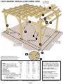
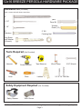
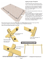
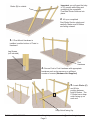
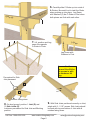
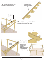
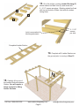
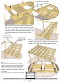
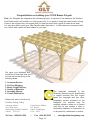
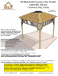
12ft X 16ft Breeze Pergola
Assembly Manual
Outdoor Living Today
Revision #8
March 20th, 2012
Note: Post Mounting Hardware is NOT included in this kit. Please confirm with your
local building permit office to determine the correct hardware in your area.
If you plan to paint or stain your Pergola before assembly, be sure to scribe or mark the
top edge of Joist where Stub Joists and Ladder Blockings are pre-marked. Painting or
staining may cover up markings, making it more difficult to align components later.
Customers agree to hold Outdoor Living Today and any Authorized Dealers free of any
liability for improper installation, maintenance and repair of any Outdoor Living Today
products.
In the event of a missing or broken piece, simply call the Outdoor Living Today
Customer Support Line @ 1-888-658-1658 within 30 days of the delivery of your
purchase. It is our commitment to you to courier replacement parts, free of charge,
within 10 business days of this notification. Replacement parts will not be
provided free of charge after the 30 day grace period.
Toll Free 1-888-658-1658
www.outdoorlivingtoday.com
Page 1
[email protected]
12X16 BREEZE PERGOLA EXPLODED VIEW
6 LADDER
SECTIONS
F
D
D
B
E
C
A
G
87 3/4” Inside
Post to Post
H
133” Inside
Post to Post
I
96” Outside Post to
Center of Center Post
144” OUTSIDE
POST TO POST
A
192” OUTSIDE
POST TO POST
J
L
Thank you for purchasing one of our
Breeze Pergola's. Please take the time to
identify all the parts prior to assembly.
K
Parts Lists:
Thickness
A - Posts
5 3/8”
B - Girder (square cut one end)
1 1/2”
C - Girder (deep notch on top)
1 1/2”
D - Joist (shallow notch on bottom) 1 1/2”
E - Stub Joist
1 1/2”
F - Blocking
1 1/2”
G - Left Brackets
1 1/2”
H - Right Brackets
1 1/2”
I - Corner Bracket Post Mount
3/4”
Post Skirting Kits - 6 Kits / Each includes:
J - Post Skirtings with Cleat 3/4”
K - Post Skirtings
3/4”
L - Post Skirting Caps
”1”
Toll Free 1-888-658-1658
Width
5
5
5
5
5
5
5
5
4
3/8”
1/2”
1/2”
1/2”
1/2”
1/2”
1/2”
1/2”
1/2”
8”
8”
1 7/8”
Length
Qty.
108”
105”
162”
162”
14 1/2”
20 1/4”
34 3/4”
34 3/4”
10 1/2”
6
4
2
14
20
60
6
6
12
8”
8”
9 1/4”
2
2
4
www.outdoorlivingtoday.com
Page 2
Specifications:
Wood Species - Western Red Cedar
Grade - Architectural Knotty or Better
Posts - Laminated Western Red Cedar
Lag Screws and Washers - Zinc Plated
4”, 2 1/2”, 1 1/4” Screws - Yellow Zinc
2” Screws - Stainless Steel
2” Finishing Nails - Stainless Steel
Overall Outside Dimensions:
162” x 210” x 108”high
Height (Ground to Bottom of Girder)
95 1/2”
Post Mounts - Not Included with Kit
Recommended Post Mount
Simpson Strong Tie - ABU66
[email protected]
12x16 BREEZE PERGOLA HARDWARE PACKAGE
Hardware Kit
(Provided)
Note: screws and nails shown actual size.
4”
Square
Drive Bit
2 1/2”
Wooden
Dowel (12)
1 1/4”
2”
Stainless
2” SS
Finishing Nail
Lag Screw
and Washer
(24 each)
Tools Required
Hammer
(Not Provided)
Screw Gun/Drill
Level
Tape Measure
Ladders
Pliers
Safety Equipment Required
Safety Glasses
Toll Free 1-888-658-1658
Wood Clamp
9/16” Wrench
1/8” & 1/4” Drill Bits
(Not Provided)
Work Gloves
www.outdoorlivingtoday.com
Page 3
[email protected]
Laying out your Footprint
To determine the proper placement of your
5 3/8” x 5 3/8” Posts, see the exploded view
on Page 2 to find the measurements and to
determine their correct positions. Outside
Post to Post measurements for the 12’x16’
Breeze are: 192” x 144”.
192”
144”
Take diagonal measurements to check your
layout for square.
We recommend that you fix Posts to ground
using Steel Post Bases or Saddle Brackets
fixed on cement footing. If attaching Posts to
pre-existing deck, we recommend that you
purchase Post / Deck Mounting Brackets. In
both cases, Post Mounting hardware can be
found at most Hardware Stores.
1. On flat level ground, lag-screw Girder (B) to two Posts (A) approximately 8” from top of Post.
Girder (B) is square cut on one end. Complete 2 sets of Girder/Post Sections.
Note; Pilot hole Post first with 1/4” drill bit.
B
8”
B
Use 2 Washers and
Lag Screws.
13.5”
Girder (B) positioned 1/2
way on Post.
A
Deep Notch facing
down and inside
flush with post.
B
Toll Free 1-888-658-1658
Completed Post/Girder (B) Section.
Use 2 Washers and
Lag Screws.
www.outdoorlivingtoday.com
Page 4
[email protected]
Important: you will need the help
of 2-3 people while lifting and
positioning the completed
Post/Side Girder Sections into
place.
Girder (B) to outside
2. Lift up a completed
Post/Girder Section slowly and
carefully. Make sure B-Girders
are facing outward.
3. If Post Mount Hardware is
installed, position bottom of Posts in
Hardware.
Lag Screws
(not included)
Post
Hardware
4. Secure Post to Post Hardware with appropriate
hardware such as lag screws or a sufficient
number of screws.(Hardware Not Supplied)
5. Locate Girder (C)
C
and lift into
position between
both B-Girders. The
C-Girder has a deep
notch facing up on
each end.
Deep Notch facing Up.
Toll Free 1-888-658-1658
www.outdoorlivingtoday.com
Page 5
[email protected]
6. Carefully slide C-Girder up into notch of
er
d
Gir
Girder (
B)
C)
(
B-Girders. Be careful not to twist the Girder
when pushing up into place. Lag Screw
with Washers (2) the C-Girder to Post when
both pieces are flush with each other.
7. Lift, position and Lag
screw the opposite
C-Girder to Posts.
C-Girde
r
Lag Screw with
Washers to Post.
You can find the
Square Drive Bit for
the screws in with
the Hardware Kit
Bag.
Pre-marked for Stub
Joist placement
D
E
Notches facing down
8. On level ground, position 1 Joist (D) and
9. With Stub Joists positioned correctly on Joist,
10 Stub Joists (E).
Joists are pre-marked for Stub Joist and Blocking
position.
attach with 2 - 2 1/2” screws. Stub Joists should
be flush with top and bottom of Joist with all
notches facing down.
Toll Free 1-888-658-1658
www.outdoorlivingtoday.com
Page 6
[email protected]
10. There are two Joist/Stub Joist
Assembly’s, complete both now.
Completed Joist/
Stub Joist Assembly.
Completed
Joist/Stub
Joist
connections.
11. Carefully lift up completed Joist/Stub Joist
Assembly and fit notches onto Girder.
1 - 4” screw
Jo
ist
(D
)
12. Attach all Stub
4” long
screws
Toll Free 1-888-658-1658
Joists and Joist to
Girder with 1 - 4”
screw per piece.
Complete both
assembly’s.
Note: Drill pilot holes
in Joists and Stub
Joists to make it
easier to screw in 4”
screws.
www.outdoorlivingtoday.com
Page 7
[email protected]
13. On a flat surface, position Ladder Blocking (F)
where marked on Main Joist (D) and screw with
2 - 2 1/2” screws per piece. Blocking should be flush
with top and bottom of Main Joist with all notches
facing down.
D
D
F
Joist is pre-marked for
blocking placement.
2 - 2 1/2”
screws
per side
Completed Ladder Section
14. Complete all 6 Ladder Sections on
the ground prior to moving to Step 15.
15. Carefully lift up one of
the Ladder Sections between
Girders. You will require a
helper to assist in lifting
Ladder Sections.
Toll Free 1-888-658-1658
www.outdoorlivingtoday.com
Page 8
[email protected]
Notch slides onto Girder
51
7”
/2”
16. Carefully slide Joist notches of Ladder Section
onto Girder. Try to align notches so they fall into place
all at once. With notches of Ladder Section all sitting
correctly on Girder, slide Section approximately 7” from
Post. Check alignment of opposite end of Ladder
Section.
Joist should sit
flush against Post.
Equally Space
Middle Ladder
Sections.
17. Set remaining Ladder Sections in place for side.
Ladder Section adjacent to Middle Post should sit flush
against Post. Equally space Middle Ladder Sections.
18. With all Ladder Sections in place,
check once more for equal spacing. When
satisfied with Ladder Section positioning,
attach to Girders with 4 - 4” screws per
Ladder. Screw from top edge of Joist down
into Girder.
Pilot hole screws first to help with screwing. Pilot Hole Joist
first and secure
with 4” screws/
Ladder Section.
Toll Free 1-888-658-1658
www.outdoorlivingtoday.com
Page 9
5 1/2”
[email protected]
(H) Right Side
Bracket
19.
There are 6 Left (G) and 6 Right Sided
Brackets (H). Corner Bracket Post Mounts (I)
must be attached to the bottom end of each
Corner Bracket before attaching to Posts.
Wooden
Dowel
(I) Corner
Bracket
Post
Mounts
Hole
20. To assist you with Bracket and Post Mount alignment, both the
end of the Bracket and Post Mount have been drilled for a Wooden
Dowel. Wooden Dowels are found in the Hardware Kit Bag. Insert
a Wooden Dowel in end of Bracket first and then push Post Mount
onto Dowel until Bracket and Post Mount are flush together. Align
Post Mount parallel with Bracket.
Bracket
and Post
Mount
aligned
parallel
with each
other.
Important: Drill pilot
holes to prevent
wood from splitting.
2 - 2 1/2” screws
21. With Bracket and Post Mount correctly aligned, screw Post Mount to Bracket with 2 - 2 1/2”
screws. Important: Drill pilot holes in Post Mounts and Bracket to prevent wood from splitting!
Complete all remaining Bracket/Post Mount connections.
Toll Free 1-888-658-1658
www.outdoorlivingtoday.com
Page 10
[email protected]
4” screws countersunk
1/2” below surface.
Bracket
Spacer flush
with bottom
of Girder.
Left Sided Bracket
Important: Posts may need to be aligned so they are
true and square to mount Corner Brackets correctly.
Use a Level to determine correct Post position.
22. Lift completed Left Sided Bracket up and align bottom of
Bracket Spacer flush with bottom of Girder. At bottom of Bracket,
align Post Mount evenly and tight against Post. When correctly
aligned, secure at top with 2 - 4” Screws. To secure Post Mount,
use 6 - 2” Stainless Steel Screws. Note: Post Mount and Top of
Bracket are pre-drilled.
23. Align and attach a Right Sided
Right Sided
Bracket
Bracket on Post as per Step 22.
Make sure both Brackets are
aligned on Post at the same height
before attaching.
Align Bracket on Post at same height.
24. Position and attach Bracket to center post as per Steps 22-23.
Toll Free 1-888-658-1658
www.outdoorlivingtoday.com
Page 11
[email protected]
25. Complete both the left and right
Brackets on each remaining center post.
Once again, make sure both brackets
are centered on post and are the same
height as the outside corner brackets.
12x16 Breeze with all Brackets attached.
Toll Free 1-888-658-1658
www.outdoorlivingtoday.com
Page 12
[email protected]
Post
Skirting
Caps (L)
Post Skirtings with Cleat (J)
dado cut
dado cut
Post Skirting
with Cleat (J)
Post Skirtings - (K)
Post Mount
26. To complete your Breeze, position 2 Post Skirtings with Cleats (J) on opposite sides of Post with
Dado cuts facing to the inside as shown above. Cleat should be aligned tight against Post and not
against Post Mount Hardware.
tongue cut
dado cut
Post Skirting (K)
27.
Slide the tongue and dado cuts of both Post Skirtings (K) Pieces into the ajoining tongue and
dado cuts of Part J. Align all skirting pieces evenly at top. Carefully secure Post Skirtings together
with with 1 - 1 1/4” screw per dado cut side. (1 per side).
Important - Drill 1/8” pilot hole first to prevent wood from splitting!
1 - 2” Stainless Screw in middle of Part J
28. Secure Skirting Unit to Post by screwing 1 - 2” SS Screw into each Post Skirting with Cleat (J).
Align Post Skirting Caps (L) tight against Post and equally from side to side of skirting frame. Nail
Cap down into Skirting with 3 - 2” SS Finishing nails per piece. Complete remaining Post Skirtings.
Toll Free 1-888-658-1658
www.outdoorlivingtoday.com
Page 13
[email protected]
Congratulations on building your 12X16 Breeze Pergola
Note: Our Pergola's are shipped as an unfinished product. If exposed to the elements, the Western
Red Cedar lumber will weather to a silvery-gray color. If you prefer to keep the cedar lumber looking
closer to the original color, we suggest that you treat the wood with a good oil based wood stain.
You may also wish to paint your new Pergola rather than stain it. In both cases we recommend that
you consult with a paint and stain dealer in your area.
We value your feedback and
would like to hear back from you
on how well we are doing in the
following areas:
1. Customer Service
2. On Time Shipping
3. Motor Freight Delivery
4. Quality of Materials
5. Assembly Manual
6. Overall Satisfaction.
Please call, write or email us at:
Outdoor Living Today
Canadian Address
9393 287th Street
Maple Ridge, British Columbia
Canada V2W 1L1
United States Address
P.O. Box 96
Sumas, Washington
USA 98295
Toll Line: 1.888.658.1658
|
Fax: 1.604.462.5333
Page 14
The materials contained in this
Assembly Manual may be downloaded
or copied provided that ALL copies
retain the copyright and any other
proprietary notices contained on the
materials. No material may be
modified, edited or taken out of context
such that its use creates a false or
misleading statement or impression as
to the positions, statements or actions.
|
[email protected]