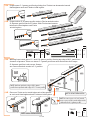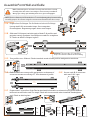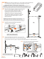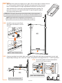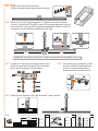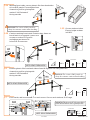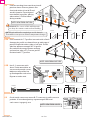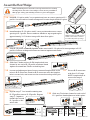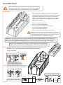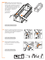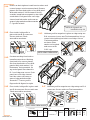
1
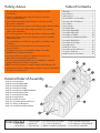
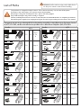
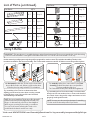
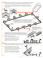
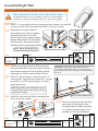
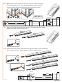
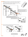
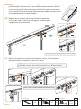
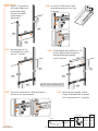
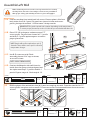
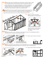
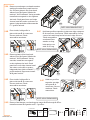
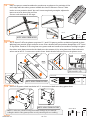
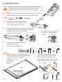
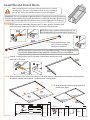
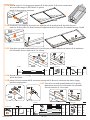
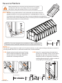
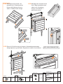
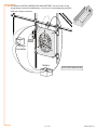
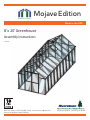
Mojave Edition
Made in the USA
8’ x 20’ Greenhouse
Assembly Instructions
041315V
WA RRAN TY
Customer Service: (877) 373-3078 Email: [email protected]
After Hours Helpline: (443) 574-4764
65 Fleetwood Drive, Rockaway, NJ 07866
Thank you for choosing the Monticello Greenhouse Program
Thank You for your Purchase
We want to thank you for your purchase of the Monticello Greenhouse. We appreciate
your support of our American Made Greenhouses.
The Monticello is designed for the average homeowner; no special degrees are needed.
The time to assemble depends on the weather, skills, options, and number of helpers
you have in the process. All the pieces are cut to size and should fit snug, BUT if
something is not working please reach out to our help lines so we can make sure that
there are no delays in the process. We are not only employees of Riverstone but
owners of Monticello Greenhouses and can help you through the process and hopefully
keep the frustration levels down if a question comes up.
We would like to take a moment to remind you as the new owner of a Monticello
Greenhouse a few things to increase the life of your greenhouse.
• Make sure that all your roof vents are closed and tied down with the included
bungee balls during high winds. This would be a 25 mph gusting wind and up.
This will help prevent air getting into the Monticello and causing damage.
• Like with the roof vents, make sure the dual doors stay closed during winds. The
doors are spring loaded to stay closed but we also know that the greenhouse can
get rather hot in the warmer months and doors do get propped open. Just make
sure that they get closed.
• In cooler snow prone climates, Cut some 2 x 4 ‘s and put them against the roof
ridge and the floor to help add support from heavy snow and ice. This is just a
precaution but could save a lot of aggravation down the road.
• It is also a good practice to clean the snow off the roof. A little snow if fine, but
several inches only will tempt fate and it is best to be safe than sorry.
• The polycarbonate panels have channels in them. These are designed to help
insulate and in moist environments, like after a rainstorm, you might find water
droplets in these channels. It will not cause any harm and will burn itself off when
the air starts to heat up.
• In some cases where there is a lot of rainfall, like the Pacific North West, we
recommend using clear silicon caulking between the polycarbonate panels and
the trim plates before the trim plates are put on. This is just to assure that the
Monticello stays as dry as possible. Just give a call if you need some more help
with this.
Lastly, we are not perfect. We know that there are better ways to do things,
we just need some suggestions from our customer base as to what they are.
Needless to say we are always open to feedback, good and bad, and we do react
to feedback. Please, if there is an option you do not see that you feel would make
the greenhouse experience better, if there is a different way to explain a set-up
process, or if there is anything else to help make Monticello better we want to
hear from you.
Thank you again for your purchase and we hope you have many years of growing in
your new Monticello Greenhouse.
David Schnurman
Vice President
MONTICELLO Limited Warranty/ Liability
Snow Load & Wind Load Warranty & Liability
The Monticello Greenhouse described in this manual is designed for and limited to Riverstone Industries standard
wind and snow load which is based on a continuously heated greenhouse. Standard loads are: Wind Load = 113
MPH/ 1 second gust (52m/sec); 65 mph continuous winds, Snow load of 24 lbs. sq ft.
Riverstone cannot and will not be held liable or responsible for any and all damages and/or structural failures caused
by prevailing load conditions at the greenhouse’s erected location that exceed the aforementioned Standard Loads.
All Monticello Wind & Snow loads are based on a closed and heated greenhouse structure. The heat provides a
source for the snow and ice to melt from the roof. If the Monticello is not being heated during the winter months when
snow and/ or ice is present it is the owners responsibility to clear the accumulations of the roof.
Contact us directly with any questions regarding this.
Products to which this limited warranty applies:
This limited warranty applies to the following models of your newly purchased Monticello Greenhouse:
MONT-8; MONT-12,MONT-16,MONT20,MONT-24, MONT-4; Premium versions, and Mojave Editions of
these greenhouses. This limited warranty applies only to purchases made in any province of Canada except
for Yukon Territory, Nunavut, or Northwest Territories or in any of the 50 States of the USA (and the District of
Columbia) except for Hawaii and Alaska. This limited warranty applies to the original purchaser of the product
only and is not transferable.
What this limited warranty covers and for how long:
Products covered by this limited warranty have been tested and inspected prior to shipment and, subject to the
provisions of this warranty, Riverstone Industries warrants such products to be free from defects in material and
workmanship for a period of 1 year from the date of the first purchase of such products.
The limited 10-year warranty period for GREENHOUSES also applies to any implied warranties that may exist under
applicable law. Some jurisdictions do not allow limitations on how long an implied warranty lasts, so the above
limitation may not apply to the purchaser.
The limited warranty for accessories follows the same guidelines as above and is covered for the following time span.
• Work Bench System – 10 years
• Watering System – 7 years
• Shade Cloth System – 7 years
• Garden/ Potting Sink – 3 years
What this limited warranty does not cover:
This limited warranty does not apply to products that have been repaired (except by Riverstone Industries or its
authorized service representatives) or otherwise altered. This limited warranty does further not apply to defects
resulting from misuse, abuse, accident, neglect, incorrect installation, improper maintenance or handling, or
operation with an incorrect power source.
Riverstone Industries is not responsible for personal time lost or paid for during the construction of
its products due to missing or defective parts.
What you must do to get service under this limited warranty:
Defects must be brought to the attention of Riverstone Industries Technical Service by contacting Riverstone
Industries at [email protected] or 612-RVR-STNE (787-7863). Please have proof of purchase,
catalog/model and serial numbers available when calling. Limited warranty service requires a proof of purchase
of the product.
What Riverstone Industries will do in the event of a defect:
In the event a product or part covered by this limited warranty is proven to be defective in material or workmanship
during the 10-year limited warranty period for products, you have the following rights:
Riverstone Industries will in its sole discretion either repair or replace such defective product or part without charge.
If Riverstone Industries is unable to repair or replace such product or part, or if repair or replacement is not
commercially practicable or cannot be timely made, Riverstone Industries may, in lieu of repair or replacement,
choose to refund the purchase price for such product or part.
Limited warranty service will be performed solely by dealers or service agents of Riverstone Industries authorized to
provide limited warranty services.
1 of 51
WWW.RSIWW.COM
Introduction
Thank you for purchasing the Mojave Edition MonticelloTM Greenhouse. The Monticello line is proudly made in the
USA by a leading commercial greenhouse maker using the same professional grade materials and design. The frame
is constructed with the highest quality extruded aluminum with lead free powder-coated paint. The panels are
professional grade 8mm twin wall polycarbonate selected for their insulation and durability.
The List of Parts has the corresponding step number referenced to each part so you can easily prepare for each
step. We recommend placing all parts in one staging area. Lay out parts by size and shape. Use the List of Parts
to identify the part numbers for profiles and panels. We have not labeled the parts with stickers to avoid removing
them during assembly.
Our greenhouse has been designed to be easily assembled. Although all but one step can be completed by one
person, we recommend using a helper for the entire assembly. You will need assistance from another person to
assemble the roof. If you have never assembled a greenhouse before, make it a weekend project. We recommend you
take your time and read these instructions carefully to avoid mistakes.
NOTE: These instructions include helpful hints and important information needed to safely assemble and properly
maintain the greenhouse. Please read these instructions completely before you begin.
Please send us photos of your new greenhouse to post on the Riverstone website.
Contact us with questions at Customer Service: (877) 373-3078
Email: [email protected] After Hours Helpline: (443) 574-4764
CAREFULLY READ ALL INSTRUCTIONS BEFORE YOU BEGIN.
FOLLOW STEPS IN THE ORDER PRESENTED. KEEP THIS MANUAL FOR FUTURE REFERENCE.
Before Starting Assembly:
1. Make sure you have all the necessary parts:
Compare the contents of the cartons with the List of Parts. If any parts are missing or damaged, contact
Riverstone Customer Service before beginning assembly. During business hours call (877) 373-3078,
email: [email protected] or use the After Hours Helpline: (443) 574-4764.
2. Lay the parts out in one staging area:
The List of Parts has the corresponding step number referenced to each part so you can easily prepare for
each step. We recommend placing all parts in one staging area. Lay out parts by size and shape. Use the List
of Parts to identify the part numbers for profiles and panels. We have not labeled the parts with stickers to
avoid removing them during assembly.
3. Select a Location:
When selecting a site for your greenhouse, a flat level surface is essential and if possible, with proper water
drainage and easy access to power and water necessary for greenhouse gardening. Choose a sunny, level
position away from overhanging trees and power lines and protected from the wind as much as possible.
The location should be away from structures that could cause snow to drift on or around the greenhouse.
Locate underground pipes or cables before preparing the site or anchoring the greenhouse.
4. Prepare a Foundation:
After choosing a location, proper preparation of the site is essential. The site must be level. The greenhouse
must be mounted to a base. Construct the base first so the greenhouse can be securely mounted.
We recommend constructing a wood platform base using a perimeter of two by fours filled with either soil,
sod or gravel. Instructions for constructing a wood platform can be found in this manual.
Other suitable base options include wood decks and concrete slabs. Wood screws are included to secure the
greenhouse to a wood base. The greenhouse is secured to the ground from the inside with ground anchors.
See step11 for details. If you are using a concrete base, get appropriate mounting screws before beginning.
Make sure the corners are square by measuring the inside diagonals from both sides and making sure they
are equal. Use a spirit level to make sure the base is level.
Contact your local authorities regarding any required building permits or restrictions.
WWW.RSIWW.COM
2 of 51
Safety Advice
Table of Contents
• The greenhouse must be positioned and fixed on a flat
level surface.
• Dispose of all plastic bags safely. Keep them out of the
reach of small children.
• Keep children and pets away from the assembly area until
the work is completed.
• Always wear work shoes, gloves and safety goggles when working.
• Some of the parts have sharp edges and burs. Use extreme
caution when handling.
• Do not lean against or push the greenhouse during assembly.
• Take special care not to touch overhead power lines with the
aluminum profiles.
• Do not attempt to assemble the greenhouse in windy or wet
conditions.
• Do not position your greenhouse in an area exposed to
excessive wind.
• If using power tools or a step ladder, always follow the
manufacturer’s safety instructions.
• Hot items such as recently used grills, blow torches etc.,
must not be stored in the greenhouse.
• Store the polycarbonate panels in a cool dark place such as a
garage until you are ready to use them.
• Make sure the greenhouse complies with local building codes.
• Heat the greenhouse during winter months to avoid accumulation
Warranty.....................................................
Introduction..............................................
Safety Advice............................................
General Order of Assembly..................
Construct Wood Platform.....................
List of Parts................................................
Using T-bolts.............................................
Assemble Base..........................................
Assemble Right Wall...............................
Assemble Back Wall................................
Assemble Left Wall..................................
Assemble Front Wall and Gable.........
Assemble Back Gable.............................
Assemble Roof Ridge.............................
Assemble Roof..........................................
Install Roof Vents.....................................
Assemble and Install Doors.................
Secure to Platform..................................
Install Fan and Solar Panel...................
8
of snow or ice on the roof.
Step 1: Assemble Base
Step 2: Assemble Right Wall
Step 3: Assemble Back Wall
Step 4: Assemble Left Wall
Step 5: Assemble Front Wall and Gable
Step 6: Assemble Back Gable
Step 7: Assemble Roof Ridge
Step 8: Assemble Roof
Step 9: Install Roof Vents
Step 10: Assemble and Install Doors
Step 11: Secure to Platform
Step 12: Install Fan and Solar Panel
7
6
9
General Order of Assembly
1
2
3
3
4
5
8
9
12
16
20
23
29
31
33
41
43
46
47
12
9
3
9
4
9
2
11
5
1
10
Goggles • 23 1/8 inch spacer (included)
Tools Needed •• Safety
Spirit Level
• / ” wrench (included)
• Step Ladder
• Work Gloves • Tape Measure • Phillips Screwdriver (included)
7
16
3 of 51
• Flat Screwdriver (included)
• 5 foot bungee cord (included)
• clear silicone caulk tube
WWW.RSIWW.COM
Constructing a Wood Platform
IMPORTANT: It is very important to begin with a level surface. Check your foundation to ensure it is level at every
point. If you are not building on a wood deck, we recommend constructing a wood platform so you can properly
secure the greenhouse. You must assure your foundation is square and level before beginning assembly.
After choosing a location, proper preparation of the site is essential. The site must be level. Create a wood
platform using a perimeter of pressure treated two by fours filled with either soil, sod or gravel.
NOTE: When constructing the greenhouse on a wood deck, make certain the
surface is level. Creating an additional wood platform is not necessary.
Buy pressure treated 2x4 lumber. You will use two layers with the corner positions staggered for maximum
strength. The finished dimensions will be 101” by 247”
Materials:
Four 10’ pressure treated 2x4 lumber cut to 97½”
Four 10’ pressure treated 2x4 lumber uncut at 120”
Four 14’ pressure treated 2x4 lumber cut to 123½“
Ninety-five #8 3” wood screws
Tools:
Spirit Level
Corner Square
Phillips Screwdiver
Power Drill (recommended)
Make sure each corner is square and then secure one corner with wood screws.
Move to the diagonal corner, make sure it is square and then secure with wood
screws. As you continue to secure the 2x4 wood platform, continue to make
certain the corners are square and the frame is level.
Secure wood platform every two feet with wood screws. Make certain to tighten screws into the wood platform
until they are flush with the surface.
NOTE: The illustrations throughout the manual are shown without a foundation.
WWW.RSIWW.COM
4 of 51
List of Parts
WARNING: Profiles with cut edges and/or drilled holes
are sharp. Use extreme caution when handling.
The greenhouse is shipped in multiple cartons. These cartons are heavy. Use care when lifting them.
Some parts have sharp edges. Use extreme caution when handling.
Wear proper safety gear including work shoes, gloves and safety goggles.
Keep children and pets away until assembly is complete.
Finish assembling the roof in one session. Do not leave the roof unattended until it is completely assembled.
Place all like parts together in a staging area. Prepare for each step according to instructions in this manual.
If any parts are missing or damaged, before beginning assembly contact Riverstone Customer Service
at (877) 373-3078, email: [email protected] or After Hours Helpline: (443) 574-4764
Profile
Profile
QTY
QTY
23”
56”
F-1
29
Steps
2,3,4,
8
F-10
2
Step 3
G-1
4
Steps
2,4
G-2
8
Steps
2,4
P-1A
4
Steps 1
P-1B
4
Steps 1
P-2A
3
Steps 1
P-2B
3
Steps 1
R-1
2
Steps 1
R-1E
3
Steps 7
25 ½”
31”
F-2
1
Step 6
48 ½”
17¼”
F-4
1
Step 5
50½”
47 ¼”
F-5
1
Step 5
23”
52⅛”
F-6
4
Steps
5,6
56”
49 ¾”
F-7
8
Steps
2,3,4,
5,6
72”
48 ½”
F-8
4
Steps
5,6
5 of 51
WWW.RSIWW.COM
List of Parts (continued)
Door Profiles
QTY
24”
WARNING: Use extreme caution when handling
panels with cut edges. The corners are sharp.
Profile
QTY
W-1
25
E-1
4
Step 10
E-2
4
Step 10
E-3
2
Step 10
E-4
1
Step 10
68½”
Steps
2,3,4
22¼”
24” x 57”
W-8
16
Step 8
68½”
24” x 57”
W-10
4
Steps 8
4
Steps
4,5
Connectors
QTY
24” x 32 ¼”
W-3
B-1
6
Step 6
B-2
9
Step 3,5
B-3
54
Steps
2,3,4,5,10
B-4
27
Step 8
B-5
24
Steps
1,2,4,7
B-7
6
Steps
5,6.7
B-8
4
Step 1
B-10
8
Step 7
24” x 15 ½”
W-4
2
Steps 5
24” x 31 ¼”
W-5
2
Steps 4
24” x 18½”
W-6
4
Steps 10
24” x 34”
W-7
1
Step 3
24” x 37¼”
41/2” x 24”
W-9
Assembled Vents
Step 3
QTY
V-4
WWW.RSIWW.COM
1
3
Steps 9
6 of 51
Hardware
List of Parts (continued)
Door Profiles
QTY
20’
Step 10
D-6
2
Step 10
D-7
1
Step 10
D-9
4
8
S-5A
S-5B
S-5D
3
11
15
Step 7
Step 8,12
Step 8,12
S-6
8
Step 9
S-7
405
S-8A
S-2A
8
8
Steps 1,2,3,4
5,6,7,8,10,11
Step 5
Step 5
S-9
38
Step 10
S-10
4
Step 10
S-11
4
Step 12
S-12
8
Step 12
S-2C
D-4
D-8
S-2A
S-2B
S-2C
S-2D
S-4
Step 9
Steps 1,2,3,4
405
5,6,7,8,10,11,12
2
Step 5
2
Step 5
2
Step 5
2
Step 5
95
Steps 11
S-1
QTY
Step 5
Step 10
16
Included Tools
D-10
2
Step 10
QTY
S-10
4
Steps
1,2,3,4,5,6,
7,8,9,10,11
T-2
1
Steps1,2,3,4,
5,6,7,8,9,10
T-3
1
Steps
2,3,4
T-4
4
Step 8
Phillips/Flat Combination Screwdriver
Trim Plates
QTY
Wrench
49 ¾”
48 ½”
G-4
4
Step 8
G-4E
4
Step 8
23 1/8” Spacer
5’ Bungee Cord
Gutter Drain
Connectors
QTY
C-1
C-2
Vent Opener
4
2
QTY
G-3
Steps
5,6
Ground Anchors
QTY
A-1
10
Step 11
A-2
10
Step 11
Brace
4
Step 8
Step 7
QTY
V-3
4
Step 9
QTY
B-9
7 of 51
4
Step 8
WWW.RSIWW.COM
List of Parts (continued)
Fan Parts
Fan Parts
QTY
H-1
2
QTY
H-6
1
Step 12
H-7
1
Step 12
H-8
1
Step 12
H-9
1
Steps 12
Step 12
H-2
2
Step 12
H-3
2
Step 12
H-4
2
Step 12
H-10 10’ Steps 12
H-5
4
Step 12
H-11
8’ Steps 12
Using T-Bolts
IMPORTANT: This greenhouse is assembled using a unique fastening system. The parts are attached to each other using
connectors fastened with a rectangular headed bolt referred to as a “T-bolt” and secured with a “2-SC cap”.
In this manual you will prepare only the profiles required for each section. This includes installing T-bolts in the
locations needed for the entire assembly. The T-bolts with connectors and S-2C bolts secure the profiles in place.
On horizontal profiles the T-bolts may be slotted into
On
horizontalfrom
profiles
the T-bolts
may
be slotted
the
the profile
the end,
slid into
position,
theninto
then
profile
from the
end,
intoincluded
position,T-5
then
then locked
locked in
place
byslid
using
screwdriver.
in place by using a screw driver.
Try installing a few T-bolts to determine how
tightly you will need to turn them so they remain
locked in place even if the profiles are knocked
around during installation.
For vertical profiles place a nut on the T-bolt (T-bolt
On vertical
profiles
you
will
place in
a nut
onand
the push
T-bolt,the
hold the
Assembly),
hold
the bracket
place
bracket in placeT-bolt
and push
the
T-bolt
(with
nut
attached
loosly)
assembly through slot.
through
slot.
The
T-bolt
will
lock
into
place
when
nut
is
tightened.
The T-bolt will lock into place when nut is tightened.
Try installing a few T-bolt Assembly’s to determine
how loose the nut needs to be to ensure the head of
the T-bolt clears the profile edges and turns to lock
properly in the profile track.
NOTE: If you are installing T-bolts in profiles that will
remain horizontal you may tighten them with your
fingers. In this manual, you will see “hand tighten”
which means securing in place with a screwdriver.
“Loosen T-bolt” means turning the T-bolt so it is
parallel in the bolt track and moves easily.
NOTE: You may use the verticle technique for attaching
T-bolts on the horizontal profiles if you desire.
Visit us at WWW.RSIWW.com/AssemblyQuestions for key assembly images and helpful tips.
WWW.RSIWW.COM
8 of 51
Assemble Base
Make certain the pieces are in the correct positions before securing.
Carefully follow the order of assembly to ensure an easy installation.
Wear proper safety gear including work shoes, gloves and goggles.
The base is made up of four P-1A, four P-1B, three P-2A and three P-2B
profiles. Arrange profiles in a rectangle as shown. Position P-2A and
P-2B profiles at back sides of the greenhouse.
WARNING: Use extreme caution when handling profiles P-1A, P-1B, P-2A
and P-2B. The bottoms may have sharp edges near the drilled holes. The
cut edges on the corners of these profiles are sharp.
IMPORTANT: Make sure the base fits properly on your
foundation. If not, stop and fix your foundation.
P-1A
P-1B
P-2B
P-2B
P-2B
P-1B
P-1A
BACK
IMPORTANT: Position
P-2A and P-2B profiles
at back of greenhouse.
FRONT
1.1
P-1A
P-1B
P-1B
P-1A
P-2A
P-2A
P-2A
Profile
QTY
50½”
521/8”
9 of 51
P-1A
4
P-1B
4
P-2A
3
P-2B
3
WWW.RSIWW.COM
1.2
Install T-bolts into inside and
outside bolt tracks as shown below.
Some of the T-bolts are secured in
this step. Most are secured in later
steps. Pay careful attention to
ensure you have the correct number
of T-bolts in the correct bolt track
in each profile. The profiles have
different amounts of T-bolts on the
inside and outside bolt tracks.
BACK
IMPORTANT: Position P-2A and P-2B
profiles at back of greenhouse.
IMPORTANT: When assembling base,
make sure the profiles are straight and
flush against each other. Secure profiles
together, and ensure corners are square.
The diagonal measurements on inside
corners should be equal. Secure corners
to desired foundation until assembly is
completed. We recommend using a two
by four platform.
T-bolt Placement Code
T-bolts used in steps 1.4A and 1.4B
T-bolts used in steps 2 through 10
T-bolts used in step 11
NOTE: Instructions identify twenty T-bolts
necessary for securing to ground in step 11.
FRONT
S-7
WWW.RSIWW.COM
107
10 of 51
1.3A Make certain side profiles are straight and flush. Adjust position of T-bolts
in inner bolt track at front of profile to fit holes in B-5 connector. Center
connector over seam for maximum hold. Secure using four S-2C caps.
Repeat on outer bolt track to install seven remaining B-5 connectors at
back and sides.
B-8
B-5
B-5
B-8
B-5
B-5
B-5
BACK
IMPORTANT: One B-5 connector is installed on inside front.
Remaining B-5 connectors are installed on outside back
and sides. B-8 corner connectors are installed on inside.
B-8
B-5
B-8
FRONT
B-5
B-5
NOTE: Connector size is
not shown proportionally
in this drawing.
B-8
B-5
B-5
IMPORTANT: Double check the position and amount of unused
T-bolts in the base. You should have 53 available for later assembly.
1.3B Make certain corners line up
and are flush. Adjust position of T-bolts
in inner bolt track to fit holes in B-8
connector. Secure with four S-2C caps.
Repeat until each corner is secure.
B-5
Connector
QTY
B-5
S-2C
Connector
10
40
QTY
B-8
S-2C
4
16
1.4A Measure base diagonally from inside corner. Equal measurements ensure the base is square.
Use a spirit level to make sure the base is level.
1.4B Locate predrilled holes in base profiles.
Use six S-4 screws, one at each corner
and one in the center of each side to secure
to wood platform. You will secure the
greenhouse completely to the platform
in step 11.1 when assembly is finished.
S-4
B-8
Connector
QTY
S-4
11 of 51
6
WWW.RSIWW.COM
Assemble Right Wall
CHECK YOUR WEATHER FORECAST. DO NOT CONTINUE ASSEMBLY DURING WINDS.
Make certain the pieces are in the correct positions before securing.
Carefully follow the order of assembly to ensure an easy installation.
Wear proper safety gear including work shoes, gloves and goggles.
2.1A Place F-7 corner profile on base, fitting panel into channel. Use two B-3
connectors with T-bolt assemblies as shown to secure to base.
2.1B Working from outside, begin at
front right corner. Remove plastic
film from both sides of one W-1
panel. Fit panel into channel in base,
placing side marked “UV Resistant”
facing outside. The panels will help
hold the profiles up during assembly.
F-7
B-3
B-3
NOTE: VIEWS FROM OUTSIDE.
Connectors
Panel
QTY
24” x 57”
W-1
Profile
QTY
56”
1
2.2A Continue working from inside. Remove plastic
film from both sides of one W-1 panel. Fit panel
into channel in base and corner profile, placing
side marked “ UV Resistant” facing outside.
2.2B Place 23 1/8 inch spacer on base next to F-7
corner profile. Fit panel into channel in F-1 profile
and slide F-1 profile against spacer to ensure
proper placement.
F-7
4
S-7
2
W-1
F-1
W-1
NOTE: VIEW FROM INSIDE.
2.2D Continue building the side wall from
the inside. Use the spacer with
each panel and the eight remaining
F-1 profiles. Repeat steps 2.2A
through 2.2C to secure to base.
B-3
WWW.RSIWW.COM
S-2C
spacer tool
F-8
Connectors
QTY
W-1
2
F-7
2.2c Use B-3 connector with T-bolt assemblies as
shown to secure to base.
24” x 57”
B-3
IMPORTANT: The panels expand and contract
depending on the temperature. To ensure proper
placement, use the 23 1/8 inch spacer included with
the tools.
NOTE: Panels will not fit completely to end of
channels. There will be some space to allow for
temperature changes.
Panel
1
QTY
8
Profile
QTY
56”
12 of 51
F-1
9
QTY
B-3
9
S-2C
18
S-7
9
2.3
Remove plastic film and add the last W-1 panel to complete the side.
From the outside, fit F-7 corner profile into place and use two B-3
connectors with T-bolt assemblies as shown to secure to base.
F-7
B-3
NOTE: VIEW
FROM OUTSIDE.
B-3
Profile
QTY
56”
F-7
Panel
Connectors
QTY
1
24” x 57”
W-1
1
QTY
B-3
2
S-2C
4
S-7
2
2.4A Slide four T-bolts into bottom bolt track of G-1 gutter profiles. Hand
tighten each end T-bolt to hold in place.
G-1
G-1
G-1
G-1
2.4b Slide T-bolts into bottom bolt track of G-2 gutter profiles, five into one and
six into the other three. Hand tighten end T-bolts to hold in place.
G-2
G-2
G-2
G-2
Profile
QTY
25½”
S-7
31
13 of 51
48½”
G-1
2
G-2
4
WWW.RSIWW.COM
2.5A Working from inside, place G-1 and G-2 gutter profiles, fitting top edge
of W-1 panels into channels of gutters. Place one short G-1 gutter
profile at each end and the four longer G-2 gutter profiles in the center.
Seams are centered to bolt tracks in F-1 profiles.
G-2
W-1
F-1
NOTE: In some cases a ¼” x ¼” notch
in top corner of W-1 panel will provide
a better fit for G-1 gutter profile.
G-1
W-1
F-1
W-1
W-1
¼”
¼”
F-7
NOTE: At front and back, edge of G-1 gutter
profile lines up flush with edge of F-7 corner profile.
G-1
NOTE: VIEW FROM INSIDE.
F-7
2.5b Place one T-bolt on the inside bolt track of the gutter at each end.
Hand tighten both T-bolts to hold in place.
G-1
G-1
W-1
W-1
F-7
F-7
NOTE: VIEWS FROM INSIDE.
S-7
WWW.RSIWW.COM
14 of 51
2
2.6A The gutters are secured together using B-5 connectors and attached to side
profiles using B-3 connectors on the outside of the greenhouse. The B-3
connector uses the T-bolt in the center hole of B-5 connectors at seams.
Loosen and slide T-bolts to line up with connectors making sure the seams
line up and the gutters remain straight.
2.6B Begin at the five seams and arrange T-bolts so middle bolt
is centered. Fit B-5 connector onto gutter and hold in place
using the two S-2C end bolts.
G-2
B-5
G-1
B-5
B-5
W-1
F-1
W-1
F-7
NOTE: VIEWS FROM OUTSIDE UNDER GUTTER.
2.6C Place B-3 connector on center T-bolt on gutter. Insert T-bolt assembly
through slot in B-3 connector to secure as shown.
NOTE: The bottom of B-3 connector extends past the edges of side and corner
profiles. B-3 connector sits over B-5 connector. Secure all with 2-SC bolts.
B-5
B-3
B-3
NOTE: VIEWS FROM OUTSIDE UNDER GUTTER.
Connector
QTY
B-5
Connector
5
15 of 51
QTY
S-7
11
Connector
QTY
B-3
S-2C
11
42
WWW.RSIWW.COM
Assemble Back Wall
CHECK YOUR WEATHER FORECAST. DO NOT CONTINUE ASSEMBLY DURING WINDS.
Make certain the pieces are in the correct positions before securing.
Carefully follow the order of assembly to ensure an easy installation.
Wear proper safety gear including work shoes, gloves and goggles.
3.1a Working from inside, remove plastic film from both sides of one W-1
panel. Fit panel into channel in base and corner profile, placing side
marked “ UV Resistant” facing outside.
IMPORTANT: The panels expand and contract depending on the temperature.
To ensure proper placement, use the 23 1/8 inch spacer included with the tools.
3.1B Position F-8 profile so the cut edge is angled
down toward the right when installed. Place
23 1/8 inch spacer on base next to F-7
corner profile. Fit panel into channel in right
F-8 profile. Slide F-8 profile against spacer
to ensure proper placement.
F-7
W-1
F-8
W-1
spacer tool
NOTE: Position F-8 profile so cut edge is angled
down towards nearest corner when installed.
WARNING: The cut edge of F-8 profile is
sharp. Use extreme caution when handling.
3.1c Use B-3 connector with T-bolt assemblies as shown to secure to base.
NOTE: ALL VIEWS FROM INSIDE.
F-8
B-3
3.1d Remove plastic film and fit the W-7 panel into
channel in base and F-8 profile. Position F-1
profile so that panel fits into channel in F-1
profile and slide F-1 profile against spacer to
ensure proper placement.
Repeat step 3.1C to secure.
F-8
W-7
F-1
spacer tool
NOTE: VIEW FROM INSIDE.
QTY
Profile
56”
72”
F-1
1
F-8
1
Panels
24” x 57”
WWW.RSIWW.COM
16 of 51
24” x 37¼”
24” x 37¼”
QTY
W-1
1
W-7
1
Connector
QTY
B-3
S-2C
S-7
2
4
2
3.1e Remove plastic film and fit another W-1 panel and fit into channel in base
and F-1 profile. Position left F-8 back profile so the cut edge is angled
toward the left when installed. Fit panel into channel in left F-8 profile
and slide F-8 profile against spacer.
Repeat step 3.1C to secure.
F-1
W-1
F-8
spacer tool
NOTE: VIEW FROM INSIDE.
NOTE: Position F-8 profile so cut edge is angled
down towards nearest corner when installed.
Connector
QTY
Profile
72”
F-8
Panels
1
24” x 57”
3.2
B-3
S-2C
S-7
QTY
W-1
QTY
2
1
2
1
Remove plastic film and add the last W-1 panel to complete the side. From the outside, fit F-7
corner profile into place and use two B-3 connectors with T-bolt assemblies as shown to secure
to base.
F-7
B-3
B-3
NOTE: VIEW FROM outSIDE.
Connector
QTY
Profile
56”
F-7
Panel
QTY
1
24” x 57”
3.3
W-1
1
QTY
B-3
S-2C
S-7
2
4
2
Prepare two F-10 profiles. Slide four S-11 connectors into bolt tracks on F-10 profiles.
F-10
F-10
Connector
QTY
S-11
17 of 51
4
Profile
QTY
23”
F-10
2
WWW.RSIWW.COM
3.4A Place F-10 profile on
W-7 panel. Make sure
profile fits snugly
between F-8 back
profile and F-1
wall profile.
3.4B Secure B-2 with three T-bolt
assemblies and one S-2C cap
as shown.
B-2
F-7
F-8
F-1
W-1
F-10
W-1
W-7
3.4c Place another F-10
Profile about 5” from
top of F-1 profile.
3.4D Fit W-9 panel into channel in F-10
profile. Adjust both so panel is
snug and lines up with top
W-9
of W-1 Profiles.
F-10
F-10
W-1
F-8
F-8
F-1
W-1
F-1
W-1
W-1
F-10
W-7
NOTE: VIEWS FROM INSIDE.
3.4E Secure B-2 with three T-bolt assemblies
and one S-2C cap as shown.
W-7
3.4F Working from outside, repeat
steps 3.4B and 3.4E to install
B-2 connectors on F-1 profiles.
B-2
Connectors
Panel
QTY
W-9
41/2” x 24”
WWW.RSIWW.COM
18 of 51
1
QTY
B-2
S-2C
S-7
4
16
4
The two sets of F-6 and F-10 profiles fit on top of W-1 panels. Line up bottom bolt
channels with top edge of F-1 and F-7 vertical profiles. Profiles will fit snugly.
3.5A Working from inside right corner, place
F-6 profile with mitered end next to
corner and angled edge facing up onto
corner W-1 panel. F-6 profile fits snugly
between F-7 corner profile and F-8
back profile.
F-6
G-1
F-7
W-1
F-8
3.5B Continue along back wall.
Place first F-10 profile.
Align with F-6 profile.
3.5c Place second F-10 profile on next W-1
panel and ensure it fits snugly between
F-1 wall profile and F-8 back profile.
F-10
F-6
F-10
F-10
W-9
F-10
W-1
W-1
F-8
W-1
F-1
W-1
F-1
F-8
NOTE: ALL VIEWS FROM INSIDE.
F-10
F-10
W-7
F-10
3.5D Place second F-6 profile with mitered end next
to corner and angled edge facing up onto corner
W-1 panel. F-6 profile fits snugly between F-7
corner profile and F-8 back profile.
3.6A Insert eleven T-bolt
assemblies in slots
in B-1 connectors.
Fit B-1 connector to
profiles as shown.
F-6
F-6
F-10
F-1
F-8
F-1
W-1
F-7
F-10
F-6
W-1
F-8
W-9
F-8
B-1
B-1
B-1
F-10
3.6B Secure B-1 connectors as shown.
NOTE: ALL VIEWS FROM INSIDE.
Profile
QTY
23”
23”
19 of 51
F-6
2
F-10
2
Connector
QTY
S-7
B-1
S-2C
11
3
11
WWW.RSIWW.COM
Assemble Left Wall
Make certain the pieces are in the correct positions before securing.
Carefully follow the order of assembly to ensure an easy installation.
Wear proper safety gear including work shoes, gloves and goggles.
4.1a Continue working from inside back left corner. Remove plastic film from
both sides of one W-1 panel. Fit panel into channel in base and corner
profile, placing side marked “ UV Resistant” facing outside.
IMPORTANT: The panels expand and contract depending on the temperature.
To ensure proper placement, use the 23 1/8 inch spacer included with the tools.
4.1b Place 23 1/8 inch spacer on base next to F-7
corner profile. Fit panel into channel in F-1 profile
and slide F-1 profile against spacer to ensure
proper placement.
F-7
W-1
F-1
W-1
spacer tool
NOTE: Panels will not fit completely to end of
channels. There will be some space to allow for
temperature changes.
4.1c Use B-3 connector with T-bolt
assembly plus an S-2C cap, as shown,
to secure to base.
F-8
NOTE: VIEWS FROM INSIDE.
4.1D Continue building the side wall from the
inside. Use the spacer with each panel and
the eight remaining F-1 profiles And W-1
panels. Repeat steps 4.1A through 4.1C.
B-3
Connector
QTY
Profile
56”
F-1
Panel
9
24” x 57”
4.2
B-3
S-2C
S-7
QTY
W-1
QTY
9
9
18
9
Remove plastic film and add the last W-1 panel to complete the side. From the outside, fit F-7
corner profile into place and use two B-3 connectors with T-bolt assemblies as shown to secure
to base.
F-7
B-3
B-3
Profile
QTY
56”
F-7
Panel
1
24” x 57”
WWW.RSIWW.COM
20 of 51
QTY
W-1
1
Connector
QTY
B-3
S-2C
S-7
2
4
2
4.3A Prepare two G-1 gutter profiles by sliding four T-bolts into bottom bolt track.
Hand tighten each end T-bolt to hold in place.
G-1
G-1
4.3B Prepare three G-2 gutter profile with six T-bolts and the other
G-2 gutter profile with five T-bolts. Slide T-bolts into bottom
G-2
bolt track. Hand tighten end T-bolt
to hold in place.
G-2
G-2
G-2
Profile
QTY
25½”
S-7
48½”
31
G-1
2
G-2
4
4.4A Working from inside, place G-1 and G-2 gutter profiles, fitting top edge of W-1 panels into
channels of gutters. Place one short G-1 gutter profile at each end and the four longer
G-2 gutter profiles in the center. Seams
G-2
are centered to bolt tracks in F-1 profiles.
G-1
W-1
F-7
W-1
G-1
F-1
W-1
NOTE: At front and back, edge of G-1 gutter
profile lines up flush with edge of F-7 corner profile.
F-7
W-1
4.4B Place one T-bolt on the inside bolt track of the gutter
at each end. Hand tighten both T-bolts to hold in place.
NOTE: VIEW FROM INSIDE.
G-1
G-1
F-1
¼”
¼”
NOTE: In some cases a ¼” x ¼” notch
in top corner of W-1 panel will provide
a better fit for G-1 gutter profile.
W-1
W-1
F-7
F-7
NOTE: VIEWS FROM INSIDE.
21 of 51
S-7
2
WWW.RSIWW.COM
4.5A The gutters are secured together using B-5 connectors and attached to
side profiles using B-3 connectors on the outside of the greenhouse.
The B-3 connector uses the T-bolt in the center hole of B-5
connectors at seams. Loosen and slide T-bolts to line up
with connectors making sure the seams line up and the
gutters remain straight.
4.5B Beginning at the seams, arrange T-bolts so middle bolt is centered.
Fit B-5 connector onto gutter and hold in place using the two S-2C end bolts.
G-2
W-1
G-1
B-5
B-5
F-1
W-1
F-7
NOTE: VIEWs FROM OUTSIDE under gutter.
4.5C Loosen T-bolts on side profiles and slide down. Place B-3 connector on center T-bolt on gutter.
Insert T-bolt assembly through slot in B-3 connector to secure as shown.Tighten T-bolts and
secure with S-2C caps.
NOTE: The bottom of B-3 connector extends past the edges of side and corner
profiles. B-3 connector sits over B-5 connector. Secure all with 2-SC bolts.
B-5
B-3
B-3
NOTE: VIEWs FROM OUTSIDE under gutter.
Connector
QTY
B-5
WWW.RSIWW.COM
Connector
5
22 of 51
QTY
S-7
11
Connector
QTY
B-3
S-2C
11
42
Assemble Front Wall and Gable
Make certain the pieces are in the correct positions before securing.
Carefully follow the order of assembly to ensure an easy installation.
Wear proper safety gear including work shoes, gloves and goggles.
NOTE: The door frame is 69¼” from the base. To avoid adjusting the placement after
assembly, prepare door frame using the exact measurements listed in these steps.
5.1A Prepare four D-8 hinges. Fit S-8 bolts in holes in D-8 hinge.
Line up with S-2A nuts under hinge. Screw together.
Do not tighten. Repeat to prepare three more hinges.
D-8
S-8
S-2A
5.1B Slide two D-8 hinges into bolt track of both F-8 profiles and
position exactly as shown. Use Phillips screwdriver to tighten
S-7 bolts to hold D-8 hinges in place.
D-8
7”
F-8
D-8
(178mm)
D-8
F-8
7”
(178mm)
WARNING: The cut edge of F-8 profile is
sharp. Use extreme caution when handling.
5.1C Turn profiles over. Slide six T-bolts into bolt track of both profiles and position as shown.
F-8
5.1d Fit B-2 connector onto profile and position so bottom of
connector measures exactly 67” from bottom of profile.
5.1e Secure each B-2 connector
with two S-2C caps.
B-2
67”
F-8
(1701mm)
B-2
B-2
5.1f Prepare two F-6 profiles. Slide T-bolts into both bolt tracks on mitered end of profile and one
bolt track on the other end. The single T-bolt will sit on outside when installed. Hand tighten
each T-bolt to hold in place.
F-6
F-6
Profile
QTY
23”
72”
F-6
2
F-8
2
Connector
23 of 51
QTY
Connector
QTY
D-8
4
S-7
18
S-8
8
B-2
2
S-2A
8
S-2C
4
WWW.RSIWW.COM
5.2A Working from inside front right corner, remove plastic film from both sides
of one W-8 panel. Fit panel into channel in base and corner profile,
placing side marked “ UV Resistant” facing outside.
IMPORTANT: The panels expand and contract depending on the temperature.
To ensure proper placement, use the 23 1/8 inch spacer included with the tools.
5.2B Place 23 1/8 inch spacer on base next to F-7 corner
profile. Position right F-8 profile so single T-bolt
is next to base on inside and the cut edge
angled down toward the nearest corner when
installed. B-2 connector is pointing towards
door opening. Fit panel into channel in F-8 profile
and slide F-8 profile against spacer to ensure
proper placement.
B-2
F-7
F-8
NOTE: Panels will not fit completely to end of channels.
There will be some space to allow for temperature changes.
5.2c Use B-3 connector with T-bolt assemblies
as shown to secure to base.
W-1
F-8
B-3
spacer tool
NOTE: VIEWS FROM INSIDE.
5.2d Continue working from inside left corner, place F-6
profile with mitered end next to corner and angled edge
facing up onto corner W-1 panel. F-6 profile fits snugly between F-7 and F-8 profiles.
5.2e Secure B-2 with two T-bolt assemblies
and one S-2C cap as shown.
F-6
B-2
G-1
F-8
W-1
F-7
NOTE: VIEWS FROM INSIDE.
NOTE: VIEW FROM INSIDE.
Panel
QTY
W-8
24” x 57”
WWW.RSIWW.COM
24 of 51
1
Connector
QTY
B-3
S-2C
1
2
Connector
QTY
B-2
S-2C
1
3
5.3A Working from inside front right corner, place 23 1/8 inch spacer on base next to
F-7 corner profile. Position left F-8 profile so single set screw is next to
base on inside and the cut edge angled down toward the nearest corner
when installed. B-2 connector is pointing towards door opening. Fit
panel into channel in F-8 profile and slide F-8 profile against spacer
to ensure proper placement.
IMPORTANT: The panels expand and contract depending on the temperature.
To ensure proper placement, use the 23 1/8 inch spacer included with the tools.
B-2
NOTE: Panels will not fit completely to end of channels.
There will be some space to allow for temperature changes.
5.3B Use B-3 connector with T-bolt
assemblies as shown to secure
to base.
F-7
F-8
F-8
W-1
B-3
spacer tool
NOTE: VIEWS FROM INSIDE.
5.3C Continue working from inside right corner, place F-6 profile with mitered end next to corner and
angled edge facing up onto corner W-1 panel. F-6 profile fits snugly between F-7 and F-8 profiles.
5.3D Secure B-2 with two T-bolt assemblies
and one S-2C cap as shown.
B-2
F-6
G-1
F-7
W-1
F-8
NOTE: VIEWS FROM INSIDE.
NOTE: VIEW FROM INSIDE.
25 of 51
Connector
QTY
B-2
S-2C
1
3
WWW.RSIWW.COM
5.4A Prepare one F-5 profile. Slide four
T-bolts into bolt tracks and position as shown.
F-5
5.4B Place one end of F-4 profile against F-5 profile on flat level surface.
Center F-4 profile to F-5 profile. Insert a T-bolt assembly into the top
slot of the B-2, place the B-2 in position and adjust T-bolts to fit B-2
connector. Secure with two additional S-2C caps.
F-4
F-4
F-4
F-4
B-2
F-5
F-5
F-5
B-2
22”
( 560mm)
22”
( 560mm)
F-5
IMPORTANT: F-4 profile is centered to F-5 profile and secured on inside with B-2 connector.
5.4C Prepare D-7 latch. Fit S-8 bolts in holes in D-7
latch. Line up with S-2A and S-2D nuts under
latch. Screw together. Do not tighten.
S-2C
S-2C
5.4D Turn profiles over and place on flat
surface. Slide D-7 latch into bolt
track of F-4 profile and slide to
bottom where two profiles meet.
S-8
D-7
D-7
F-4
S-2D
S-2D
S-2B
S-2B
S-2A
S-2A
5.4E Using wrench, tighten 2-SC caps to hold D-7 latch in place.
F-4
D-7
D-7
F-5
F-5
Profile
QTY
17¼”
47 ¼”
WWW.RSIWW.COM
F-4
1
F-5
1
Connector
26 of 51
QTY
D-7
1
B-2
1
S-7
6
Connector
QTY
S-2A
S-2B
S-2C
S-2D
2
2
2
8
5.5A Working from inside, remove plastic film from both sides
of two W-3 panels. Fit each panel into
channels in profiles, placing side
marked “ UV Resistant”
W-3
facing outside.
W-3
WARNING: The corners of W-3 panels are
sharp. Use extreme caution when handling.
5.5C Secure with two bolts.
Ensure height to base
is 68¾”.
5.5B Continue working from inside. Position door frame so
barrel latch is on outside. Loosen set
screws on ends of F-5 profile
and adjust position to fit
F-5
holes in B-2 connector.
B-2
F-5
B-2
B-2
Panel
NOTE: VIEWS FROM INSIDE.
5.6
QTY
W-3
Connector
2
QTY
S-2C
2
24” x 15 ½”
Remove plastic film from both sides of two W-5 panels. Fit each panel into
channels in profiles, placing side
marked “ UV Resistant”
WARNING: The corners of W-5 panels are
facing outside.
sharp. Use extreme caution when handling.
W-5
W-5
NOTE: VIEWS FROM INSIDE.
Panel
QTY
W-5
2
24” x 18 ½”
5.7
From inside, add connectoaB-7 to each corner. Secure each with two S-2C caps.
F-6
G-1
IMPORTANT: Bolt track of F-6 front profile is
lower than bolt track of G-1 gutter profile.
Connector
B-7
F-7
NOTE: VIEWS FROM INSIDE.
27 of 51
QTY
B-7
S-2C
2
4
WWW.RSIWW.COM
5.8A From outside fit F-7 profiles into each side of front. Begin with either
side. Arrange F-7 profile so channel lines up with tops of panels. The
side of the profile rests against cut angle of F-8 profile. The top end
F-4
touches edge of F-4 center profile and bottom end touches top of
G-1 gutter. Position both F-7 profiles.
NOTE: VIEW FROM OUTSIDE.
F-7
F-7
F-4
G-1
F-8
F-8
F-8
G-1
F-4
5.8B Use C-1 connector with three T-bolt assemblies to secure each outside corner. Make sure all
profiles line up flush against each other. Repeat on other side.
F-7
C-1
G-1
F-6
F-8
F-7
NOTE: VIEW FROM OUTSIDE.
5.8C Check inside corners to ensure B-7 connector is still in
proper position. If it needs adjusting, repeat steps 5.7
and 5.8C through 5.8D until
each corner is set.
NOTE: VIEWS FROM INSIDE.
G-1
F-6
B-7
F-7
Profile
QTY
56”
WWW.RSIWW.COM
F-7
28 of 51
2
S-7
4
C-1
2
S-2C
6
Assemble Back Gable
Make certain the pieces are in the correct positions before securing.
Carefully follow the order of assembly to ensure an easy installation.
Wear proper safety gear including work shoes, gloves and goggles.
6.1A Working from inside, place F-2 profile on F-1 profile.
Make sure profiles are straight.
6.1b Secure to B-1 connector with
one T-bolt assembly.
F-2
F-10
F-10
F-11
F-1
Profile
QTY
31”
NOTE: VIEWS FROM INSIDE.
F-2
Connector
QTY
S-7
S-2C
1
4
1
From inside, add connector B-7 to each corner. Secure each with two S-2C caps.
6.2
F-6
IMPORTANT: Bolt track of F-6 front profile is
lower than bolt track of G-1 gutter profile.
G-1
Connector
B-7
QTY
B-7
S-2C
F-7
2
4
6.3A Work from outside to add B-1 connectors in the same position as inside. Loosen T-bolts on
profiles and adjust position to fit holes in B-1 connectors. Fit B-1 connector to profiles.
F-8
F-2
F-8
F-10
B-1
B-1
6.3b Secure each B-1
connector as shown.
F-10
F-1
B-1
Connector
NOTE: VIEWS FROM OUTSIDE.
29 of 51
QTY
B-1
S-2C
3
12
WWW.RSIWW.COM
6.4
Continue working from outside to install
panels a shown. Remove plastic film
from both sides of two W-3 and
two W-4 panels. Fit each panel
W-3
into channel in profiles, placing
side marked “ UV Resistant”
facing outside.
W-4
W-4
W-3
NOTE: VIEW FROM OUTSIDE.
WARNING: The corners of W-3 and W-4 panels
are sharp. Use extreme caution when handling.
Panel
NOTE: Panels will not fit completely to end of channels.
There will be some space to allow for temperature changes.
QTY
24” x 15 ¼”
QTY
24” x 30 ¾”
W-3
6.5A From outside fit F-7 profiles into each side of back.
Arrange the profile so channel lines up with tops of
panels. Begin with either right or left side. Profile
side fits against cut angle of F-8 profile.
One end touches top of gutter and top
end touches edge of F-2 center profile.
Position both F-7 profiles.
Panel
2
W-4
2
F-7
F-2
F-7
F-8
F-8
NOTE: VIEW FROM OUTSIDE.
6.5B Use C-1 connector with
three T-bolt assemblies to
secure each outside corner.
Make sure all profiles line
up flush against each other.
Repeat on other side.
F-7
C-1
G-1
F-6
F-7
Profile
QTY
56”
6.6
F-7
Connector
2
QTY
S-7
Check inside corners to ensure B-7 connector is still in correct
position. If it needs adjusting, repeat steps 6.5B until
each corner is properly set.
NOTE: VIEW FROM INSIDE.
WWW.RSIWW.COM
30 of 51
Connector
QTY
C-1
S-2C
4
G-1
F-6
B-7
F-7
2
6
Assemble Roof Ridge
Make certain the pieces are in the correct positions before securing.
Carefully follow the order of assembly to ensure an easy installation.
Wear proper safety gear including work shoes, gloves and goggles.
7.1A Install B-10 splice with C-curve positioned next to center opening in R-1
profile. Use screwdriver handle to tap until friction dimple holds it in place.
7.1B Install another B-10 splice with C-curve positioned next to center
opening in R-1 profile. Use screwdriver handle to tap to push splice
approximately 1/4” farther into profile than first splice.
NOTE: Position each B-10 splice
with C-curve next to center in
R-1 and R-1E profile openings.
R-1
7.1C Slide R-1E profile toward R-1 profile. Make sure both B-10 splices fit into openings in R-1E
profile. Continue sliding until seams are butted against each other.
R-1
R-1E
7.1D Slide four T-bolts and one S-5A long hex bolt into
channel in one end of R-1E profile as shown. Hand
tighten first and last T-bolts to hold in place.
R-1E
7.1e Loosen and adjust position of set screws and long hex bolt to fit
holes in B-5 connector. Position B-5 connector with the long hex
bolt in center hole, and center to the seam where the profiles join.
B-5
7.1f Secure B-5 connector
with four S-2C caps.
NOTE: Long hex bolt is
secured in step 8.
R-1
R-1E
7.2A Repeat step 7.1 to install remaining two
R-1E profiles next to R-1E profile. Repeat
step 7.1 again to
install the second
R-1 profile on the
other side.
Profile
7.2B Slide one T-bolt into channel in each end of
R-1 profiles. Hand tighten to hold in place.
R-1
R-1
QTY
49¾”
48½”
R-1
2
R-1E
3
31 of 51
B-10
B-5
S-2C
8
4
16
S-7
S-5A
18
4
WWW.RSIWW.COM
7.3A Use two people and a step ladder. Place step ladder inside greenhouse. Hold
the roof ridge with the screws FACING UP until it is in position. Have one
person inside greenhouse supporting ridge as you slide it into position.
Avoid touching top of front and back of greenhouse until each end is
flush with ends of front and back profiles. Turn the roof ridge over
so bolts face down and rest on top of front and back walls.
WARNING: Use two people to install roof ridge. Place ladder in inside of greenhouse.
One person will stand on the ladder holding the ridge with screws FACING UP until
it is in the proper position. Turn over so bolts face down and secured in place.
7.3B Make sure end of roof ridge is
flush to profiles on front and back.
R-1
R-1E
R-1
R-1E
R-1E
R-1
F-7
F-7
In some cases the corner points
might need to be trimmed down if
roof ridge is sitting on points.
See orange.
7.4A Working from inside, secure roof ridge to front end wall. Loosen T-bolts and adjust position
to fit holes in B-7 connector. Secure with two bolts.
7.4B Repeat step 7.4A to secure back.
F-7
Connector
B-7
F-7
QTY
B-7
S-2C
NOTE: VIEWS FROM INSIDE.
2
4
7.5A Working from outside, ensure all pieces are still flush and secure roof ridge to front. Loosen set
screws and adjust position to fit holes in C-2 connector. Secure with three bolts.
7.5B Repeat step 7.5A to secure back.
C-2
Connector
NOTE: VIEWS FROM OUTSIDE.
WWW.RSIWW.COM
32 of 51
QTY
S-7
6
C-2
S-2C
2
6
Assemble Roof
Make certain the pieces are in the correct positions before securing.
Carefully follow the order of assembly to ensure an easy installation.
Wear proper safety gear including work shoes, gloves and goggles.
1
6
3
The roof panels are installed in the sections shown below.
Use two people and a step ladder to assemble the roof. Place
step ladder inside greenhouse. Have one person stand on
ladder inside and guide panel into channels in roof ridge and
corner profiles. The other person supports the end of the
panel from the outside.
1
3
4
3
4
6
5
4
6
5
5
Section 1: Back two W-8 panels
Section 2: Front two W-8 panels
Section 3: Next three W-8 panels from back
Section 4: Next three W-8 panels
Section 5: Next five W-8 panels
Section 6: Final W-8 panel and four W-10 panels
5
6
5
2
2
6
WARNING: Use two people to install roof. Allow enough time
to complete this step and install and secure roof. Do not leave
roof unattended until it is completely assembled.
IMPORTANT: The panels expand and contract depending on the temperature. Under some conditions, the
panels may require slight force to install. Do not use excessive force or you may move profiles out of position.
When you are having difficulty sliding the panels, use dish soap with water on the edges as a lubricant.
NOTE: Use the included five foot bungee cords for added support. They will help
hold the sides in position while assembling the roof. Remove as you install profiles.
8.1A Working from the inside, Insert T-bolt assembly into B-4 connector and
install on every other side profile on both sides of greenhouse.
Secure as shown.
bungee cord
F-1
B-4
bungee cord
bungee cord
NOTE: VIEWS FROM INSIDE.
bungee cord
8.1b Hook one end of bungee cord into top
hole in B-4 connector on each side.
NOTE: VIEW FROM OUTSIDE.
Connector
NOTE: VIEWS FROM INSIDE.
S-7
QTY
QTY
8
4
5’ Bungee Cord
33 of 51
Connector
QTY
B-4
S-2C
8
8
WWW.RSIWW.COM
8.2A Working from back right corner, remove plastic film from both sides of one
W-1 panel. With side marked “ UV Resistant” facing outside, fit top end of
panel into channel in R-1 roof ridge near corner. Push panel into roof ridge
channel until the other end rests on gutter ledge and then slide towards
F-7 corner profile. Repeat to install W-8 panel in back left corner.
R-1
F-7
W-8
G-1
W-8
F-7
R-1
R-1
F-7
W-8
W-8
F-7
G-1
W-8
G-1
NOTE: VIEWS FROM OUTSIDE.
8.2B Fit one F-1 profile next to right panel. F-1 profile rests against widest part of roof
ridge and lines up with top of gutter.
8.2C From inside, hold profile in
place with one B-4 connector.
Secure with two T-bolt
assemblies as shown.
R-1
R-1
W-8
F-1
W-8
F-1
W-8
F-1
B-4
F-1
G-1
G-1
F-1
NOTE: VIEWS FROM OUTSIDE.
NOTE: VIEWS FROM INSIDE.
8.2D Repeat step 8.2B through 8.2C to secure install and secure F-1 profile on left side.
8.2E Hold two profiles together at ridge using one B-4 connector. Secure with two T-bolt assembies .
R-1
F-1
NOTE: VIEWS FROM INSIDE.
F-1
B-4
Connector
QTY
S-7
Panel
6
W-8
24” x 57”
WWW.RSIWW.COM
34 of 51
QTY
2
Connector
QTY
B-4
S-2C
3
6
8.3A Remove plastic film from both sides of one
W-8 panel. With side marked “ UV Resistant”
facing outside, install the next panel on
the right at the back. Push panel into
roof ridge channel until the other end
rests on gutter ledge and then
slide towards F-1 profile at
back. Repeat
to install W-8
panel on left.
W-8
W-8
NOTE: VIEWS FROM OUTSIDE.
8.3b Fit one F-1 profile next to panel. Fit lower end
into B-4 connector and secure with one T-bolt
assembly as shown. Repeat to install F-1
profile on opposite side.
F-1
F-1
B-4
NOTE: VIEWS FROM INSIDE.
8.3C Hold two profiles together at ridge
using one B-4 connector. Secure with
two T-bolt assembies .
B-4
F-1
R-1
F-1
B-4
NOTE: VIEWS FROM INSIDE.
Connector
QTY
S-7
Panel
6
W-8
24” x 57”
35 of 51
QTY
2
Connector
QTY
B-4
S-2C
3
6
WWW.RSIWW.COM
8.4A Return to back right to install section three and
remove bungee cord nearest to back. Remove
plastic film from both sides of one W-8 panel.
With side marked “ UV Resistant” facing
outside, install the next panel on the right
at the back. Push panel into roof ridge
channel until the other end rests on
gutter ledge and then slide towards
F-1 profile at back.
W-8
panels are
*NOTE: W-10
installed in step 8.8
8.4B From inside, hold profile in
place with one B-4 connector.
Secure with two T-bolt
assemblies as shown.
B-4
8.4C
F-1
F-1
NOTE: VIEWS FROM INSIDE.
8.4D Continue working from back to
install section three. Working
from back left, remove plastic
film from both sides of one W-8
panels. With side marked “ UV
Resistant” facing outside, fit
top end of panel into channel in
R-1 roof ridge near corner. Push
panel into roof ridge channel
until the other end rests on
gutter ledge and then slide
towards F-7 corner profile.
Repeat for W-8 panel on right.
F-1
B-4
W-8
W-8
8.4E From inside, hold profile in place with
one B-4 connector. Secure with two
T-bolt assemblies as shown.
B-4
Hold two profiles together in place at ridge using one
B-4 connector. Insert two T-bolt assemblies, line up
center hole with long hex bolt in roof ridge. Secure
T-bolt assemblies
F-1
as shown.Place
R-1
washer on long bolt
and secure with
S-2C cap.
8.4F Hold two profiles together at ridge using one B-4
connector. Secure with two T-bolt assembies.
R-1
F-1
F-1
F-1
F-1
B-4
NOTE: VIEWS FROM INSIDE.
Connector
QTY
S-7
Panel
W-8
10
24” x 57”
WWW.RSIWW.COM
36 of 51
QTY
3
Connector
B-4
S-2C
S-5B
QTY
4
11
1
8.5A Remove next bungee cord and continue working from
back to install section four. Remove plastic film
from both sides of one W-8 panel. With side W-8
marked “ UV Resistant” facing outside,
install the next panel on the left at the back.
Push panel into roof ridge channel until the
other end rests on gutter ledge and then
slide towards F-1 profile at back.
NOTE: VIEW FROM OUTSIDE.
8.5B From inside, hold profile in place with 8.5C
one B-4 connector. Secure with two
T-bolt assemblies as shown.
B-4
F-1
F-1
Hold two profiles together in place at ridge using one
B-4 connector. Insert two T-bolt assemblies, line up
center hole with long hex bolt in roof ridge. Secure
T-bolt assemblies
F-1
R-1
as shown.Place
washer on long
bolt and secure
with S-2C cap.
F-1
B-4
NOTE: VIEWS FROM INSIDE.
8.5D Remove plastic film from both sides of one W-1 panel.With
side marked “ UV Resistant” facing outside, install the
next panel on the right at the back. Push panel into roof
ridge channel until the other end rests on gutter ledge and
then slide towards F-1 profile at back. Repeat to install
W-8 panel on left.
W-8
W-8
NOTE: VIEW FROM OUTSIDE.
8.5E From inside, hold profile in place with one B-4 connector.
Secure with two T-bolt assemblies as shown.
B-4
F-1
F-1
NOTE: VIEWS FROM INSIDE.
8.5f Hold two profiles
together at ridge
using one B-4
connector. Secure
with two T-bolt
assembies.
Connector
QTY
S-7
B-4
QTY
W-1
24” x 57”
37 of 51
F-1
Panel
10
F-1
R-1
3
Connector
B-4
S-2C
S-5B
QTY
4
11
1
WWW.RSIWW.COM
8.6A Remove next bungee cord and continue
working from back to install section
five. Remove plastic film from both
sides of one W-8 panel. With side
marked “ UV Resistant” facing outside,
install the next panel on the right at
the back. Push panel into roof ridge
channel until the other end rests on
gutter ledge and then slide towards
F-1 profile at back.
8.6B From inside, hold profile in
place with one B-4 connector.
Secure with two T-bolt
assemblies as shown.
B-4
NOTE: VIEW FROM OUTSIDE.
Hold two profiles together in place at ridge using one
B-4 connector. Insert two T-bolt assemblies, line up
center hole with long hex bolt in roof ridge. Secure
T-bolt assemblies
F-1
R-1
as shown.Place
washer on long
bolt and secure
with S-2C cap.
8.6C
F-1
NOTE: VIEWS FROM INSIDE.
F-1
8.6D Remove plastic film from both
sides of one W-8 panel. With side
marked “ UV Resistant” facing
outside, install the next panel
on the right at the back. Push
panel into roof ridge channel until
the other end rests on gutter
ledge and then slide towards F-1
profile at back. Repeat to install
W-8 panel on left.
8.6E From inside, hold profile in
place with one B-4 connector.
Secure with two T-bolt
assemblies as shown.
B-4
W-8
F-1
F-1
B-4
W-8
W-8
8.6f Hold two profiles
together at ridge
using one B-4
connector. Secure
with two T-bolt
assembies.
F-1
R-1
F-1
B-4
NOTE: VIEWS FROM INSIDE.
F-1
8.6g Remove final bungee cord and repeat steps 8.6D through 8.6F to
install next two W-8 panels and F-1 profiles.
Connector
QTY
S-7
Panel
14
W-8
24” x 57”
WWW.RSIWW.COM
38 of 51
QTY
5
Connector
QTY
B-4
S-2C
S-5B
5
16
2
8.7A Continue working from back to install section six.
Remove plastic film from both sides of one W-8
panel. With side marked “ UV Resistant”
facing outside, install next panel at
W-10
slight angle on left. If necessary,
loosen the previous B-4 connector
and profile and move them
W-10
towards the back of the
greenhouse to make
W-8
more room to fit
panel in place.
W-10
W-10
NOTE: VIEWS FROM OUTSIDE.
W-8
8.7B Remove plastic film from both sides of one W-10 panel. It will
be installed opposite the W-8 panel installed in 8.7A. Second
section from front right. From outside position panel with
extended ledge profile at outside top. Install panel at slight
angle sliding all the way into profile. Fit other end into opposite
profile. If necessary apply slight pressure to bend panel and
snap into place.
F-1
F-1
F-7
W-10
8.7C Remove plastic film from both sides of second W-10 panel and
repeat step 8.7B to install in second section from back left.
F-7
F-1
F-1
W-8
W-10
8.7C Remove plastic
film from both
sides of second
W-10 panel and
repeat step
8.7B to install
in fifth section
from front right.
8.7D Remove plastic film
from both sides of
second W-10 panel
and repeat step
8.7B to install in
fouth section from
back right.
W-8
F-1
F-1
F-1
W-10
F-1
F-1
F-1
W-8
NOTE: VIEWS FROM OUTSIDE.
W-10
Panel
QTY
W-8
24” x 57”
39 of 51
Panel
QTY
W-10
1
4
24” x 32 ¼”
WWW.RSIWW.COM
8.8
Have one person stand outside the greenhouse to observe the position of the
roof ridge while the other person installs the four B-9 braces. Insert T-bolt
in the correct position, but if the roof is not completely straight, adjust the
brace to raise or lower the roof line.
Secure each with two S-2C caps.
Brace
B-9
QTY
B-9
S-2C
NOTE: VIEWS FROM INSIDE.
8.9
4
8
The G-4 and G-4E trim plates snap into G-1 and G-2 gutter profiles to hold roof panels in place.
Working from outside, begin at front corner. Run a bead of silicone sealant along ledge of G-1 and
G-2 profiles. Position G-4 trim plate over gutter and use handle of screw driver to tap into place.
Use three trim plates on each side. Make sure the seams of the trim plates are flush with each
other and to the C-1 connectors at the front. Add a bead of silicone where trim plates meet.
G-1
F-7
W-10
G-4
W-10
C-1
G-4
F-7
NOTE: View for alignment
of G-4 and G-1 only.
G-1
Trim Plate
QTY
49 ¾”
G-1
NOTE: VIEWS FROM OUTSIDE.
48½”
G-4
4
G-4E
6
8.10 Screw G-3 gutter drain into holes in C-1 connectors. Make sure they point down.
C-1
G-3
NOTE: VIEWS FROM OUTSIDE.
NOTE: To aid in rain collection and prevent water leakage we recommend
sealing the inside of the gutter profiles at each joint using silicone caulking.
WWW.RSIWW.COM
40 of 51
Gutter Drain
QTY
G-3
4
Install Roof Vents
Make certain the pieces are in the correct positions before securing.
Carefully follow the order of assembly to ensure an easy installation.
Wear proper safety gear including work shoes, gloves and goggles.
9.1A Unpack contents of Automatic Window Opener. Screw adjusting
knob partially into threaded end of cylinder. Do NOT tighten.
adjusting knob
cylinder
9.1B
9.1B Fit piston rod connected to arm B into
end of cylinder. Turn cylinder so holes
next to adjusting knob are visible.
cylinder
piston rod
9.1C Continue pushing cylinder onto piston rod until holes
in end of cylinder line up with holes in arm A. Push
arms apart if necessary. Secure with
a threaded stud on each side.
arm B
9.1D Turn adjusting screw clockwise
until arms are approximately
6” apart.
arm A
9.1E Repeat steps 9.1A through 9.1D
to prepare three more
Automatic Window Openers.
Handle
QTY
4
9.2A Remove plastic film from both sides of V-4
factory assembled vents. With side labeled
“ Face inside” facing up, lay panel
on flat clean surface.
Measure and
mark center
of vent.
Cylinder
QTY Adjusting Knob QTY Threaded Stud QTY
8
4
4
9.2B Place opener with arm A on bottom
inside vent, align with center mark.
Mark screw placement. Using S-1
screw, apply pressure to puncture the
panel and predrill holes for next step.
S-1
V-4
arm A
V-4
Center line for Arm A
Factory Assembled Vent
QTY
24” x 24 ¾”
V-4
41 of 51
4
WWW.RSIWW.COM
9.2C Screw two S-1 screws through V-4 panel. Line up gripping channel on other side.
Continue to screw until secure. Do not over tighten as it may damage the vent.
V-4
gripping
channel
9.2D Repeat steps 9.2A through
9.2C to prepare three more vents.
V-4
S-1
Connector
NOTE: VIEWS FROM INSIDE.
NOTE: VIEW FROM OUTSIDE.
QTY
S-1
Gripping Channel
QTY
8
4
9.3A From inside, hold Window Opener closed against vent. Slide vent at an angle through opening in
roof panels. Hook top lip of vent
onto curve in ridge
V-4
profile R-1.
R-1
V-4
R-1
NOTE: VIEW FROM OUTSIDE.
NOTE: VIEWS FROM FRONT
9.3B Outside of vent rests on top of ledge on W-10 profile. Open vent to attach the other arm of
opener to top of inside W-10 profile. Position with arm overlapping trim so adjusting screw can
move freely. Screw two S-1 screws through panel and into gripping channel on other side to
secure. Do not over tighten as it may damage the vent.
gripping
channel
W-10
V-4
W-10
gripping
channel
S-1
W-10
NOTE: Make sure arm A overlaps aluminum trim on W-10
S-1
9.3C Repeat steps 9.3A through 9.3B to install three
Connector
QTY Gripping Channel
more vents.
NOTE: VIEWS FROM INSIDE.
S-1
8
QTY
4
9.4A From inside screw S-6 screw and spacer into the holes
on each end of the top of the vent. This will secure the vent to the greenhouse in windy conditions.
R-1
9.4B Repeat steps 9.4A to
secure three more vents.
S-6
V-4
V-4
V-4
S-6
Connector
S-6
S-6
W-10
WWW.RSIWW.COM
NOTE: VIEWS FROM INSIDE.
42 of 51
QTY
S-6
8
Assemble and Install Doors
Make certain the pieces are in the correct positions before securing.
Carefully follow the order of assembly to ensure an easy installation.
Wear proper safety gear including work shoes, gloves and goggles.
IMPORTANT: You are assembling a right and left door. Facing the front of the greenhouse
from the outside with the doors closed, the left door is on the left side of the greenhouse
and the right is on the right side. The left door closes over the right and locks at the top.
10.1A Begin right door assembly. Prepare one E-2 door profile. Position with
holes facing up. Slide one D-9 corner connector into each end.
NOTE: D-9 corner connectors are hollow on one
end. Install with hollow end in either direction.
E-2
D-9
S-9
E-2
10.1B Secure each corner with
one S-9 screw using a
Phillips screwdriver.
NOTE: Holes in D-9 connectors are not predrilled. Using S-9 screw, apply pressure
to puncture. Hand tighten using supplied screwdriver. Do not over tighten.
10.1c Slide E-1 door profiles into D-9 corner connectors and secure each
with one S-9 screw.
E-1
S-9
D-9
E-1
E-1
10.1D Remove plastic film from both sides of two W-6 panels. Fit panels into channels in door profiles
as shown, placing side marked “ UV Resistant” facing down.
10.1E With slotted side facing up, slide E-3
profile into place.
W-6
W-6
Profile
E-3
QTY
22¼”
24”
68½”
E-3
1
E-1
2
D-9
2
E-2
1
S-9
4
43 of 51
Connector
QTY
Panel
QTY
W-6
2
24” x 34”
WWW.RSIWW.COM
10.2A Repeat step 10.1A to prepare another E-2 door profile. D-9 corner connectors
are secured in step 10.2B. Slide E-2 profile
into E-1 door profiles as shown.
E-1
E-2
E-2
D-9
10.2B Position E-4 on top of E-2 profile. Line up holes in E-4 profile with E-2 profile. Secure
with five S-9 screws. The final S-9 screw, right below the E-3 profile, is installed in step 10.6B.
E-4
S-9
E-4
S-9
E-2
E-4
E-2
10.2C Turn door over and install handle on E-2 profile just secured. Match two holes in E-2 with holes
in D-6 handle. Secure with two S-10 screws.
S-10
D-6
E-3
S-10
E-2
E-4
Profile
QTY
68½”
E-4
Connector
1
QTY
Connector
QTY
D-9
2
D-6
1
S-9
12
S-10
2
10.3A Repeat step 10.1 through 10.2A to assemble left door. Secure D-9 corner connectors with
two S-9 screws.
10.3B Using S-9 screw, attach B-3 connector to top left D-9 corner connector as shown. Apply
pressure to puncture.
10.3c Turn door over and install handle on E-2 profile.
Match two holes in E-2 with holes in D-6 handle.
B-3
Secure with two S-10 screws.
S-9
D-6
D-9
S-10
S-10
E-2
E-2
E-1
Profile
Connector
QTY Panel
B-3 1
S-9 1
WWW.RSIWW.COM
QTY
22¼”
E-3
1
24”
E-1
2
E-2
2
QTY
W-6
2
68½”
24” x 34”
44 of 51
Connector
QTY
D-6
1
S-10
2
D-9
4
S-9
8
10.4A
S-9
F-8
NOTE: VIEWS FROM OUTSIDE.
D-9
IMPORTANT: Make sure door is level. When
necessary loosen screws holding D-8 hinge
to F-8 profile and repostion until it is level.
E-2
S-9
10.4B Install left door assembled in step 10.3. Line up
holes in D-8 hinges with holes in E-2 door profile.
Secure each hinge with two S-9 screws and make
sure door is level. Make sure D-7 latch fits into
B-3 connector to lock doors.
D-7
Connector
B-3
10.5 Working from the outside with doors all the
way open, apply the D-4 door sealant
tape to the outside of F-8 and F-5
profiles that make up the door
frame and to inside E-1
bottom door profiles.
This tape acts as
F-8
insulation. Make sure
it is smooth and even.
QTY
S-9
D-4
F-5
F-8
D-4
D-4
Door Sealant Tape
E-1
NOTE: VIEW FROM OUTSIDE.
D-4
8
E-1
P-1A
P-1B
QTY
D-4 20’
D-4
10.6A Working from inside, with left door open and right door closed. Attach D-10 spring to hole in E-1
door profile using one S-9 screw. Strech spring and attach other side to T-bolt on F-8 profile.
Secure with S-2C cap.
E-3
E-3
10.6B Close left door and repeat step 10.6 A to
install spring on other door. The springs will
pull the doors closed.
F-8
E-2
Connector
D-10
S-9
D-10
QTY
S-2C
S-2C
NOTE: VIEWS FROM INSIDE.
45 of 51
2
Connector
QTY
D-10
2
S-9
2
WWW.RSIWW.COM
Secure to Platform
Make certain the pieces are in the correct positions before securing.
Carefully follow the order of assembly to ensure an easy installation.
Wear proper safety gear including work shoes, gloves and goggles.
11.1 The base has predrilled holes in the inside and outside bolt channels
making it easy to secure your greenhouse to a wood platform. Use one
S-4 wood screw in each hole in the base. Screw through the wood platform
until each screw is flush with base profile. Continue process around outside and
inside until greenhouse is evenly secured.
S-4
Connector
QTY
S-4
NOTE: The S-4 screw is designed to be used with wood. When securing base to
foundations made of materials other than wood, use an appropriate fastener.
89
Use ten A-1 ground anchors with six A-2 anchor brackets on the inside of the greenhouse to secure it
to the ground. Place one on each side at the front, center and back.
11.2a Attach anchor bracket with two T-bolts
in the inside bolt channels in base profile.
Secure with two S-2C caps. Repeat to
install nine remaining brackets.
11.2B Insert A-1 ground anchor through hole in
center of A-2 bracket. Place a screw driver
through the top of A-1 anchor to screw
completely into soil. Repeat to install nine
remaining ground anchors. Make certain all
are properly secured in ground.
A-1
A-2
Ground Anchor
QTY
A-1
WWW.RSIWW.COM
10
46 of 51
Bracket
QTY
A-2
S-2C
10
20
Install Fan and Solar Panel
Make certain the pieces are in the correct positions before securing.
Carefully follow the order of assembly to ensure an easy installation.
Wear proper safety gear including work shoes, gloves and goggles.
12.1A Working from inside, fit H-8 fan
over S-11 bolts in F-10 profiles.
S-11
NOTE: VIEW FROM INSIDE.
W-9
12.1B Secure with S-2D nut and S-5B washer.
F-10
S-2D
S-11
7
S-5B
S-11
F-10
H-8
W-1
F-10
W-1
Side View
Fan
S-11
Connectors
QTY
S-2D
S-5B
W-7
12.2A Working from inside install two T-bolts
into track, lock into place. Fit H-7
thermostat on T-bolts.
QTY
H-8
4
4
1
12.2B Secure with S-2C caps.
S-2C
H-7
H-7
S-2C
NOTE: VIEWS FROM INSIDE.
Thermostat
Connectors
QTY
S-7
S-2C
47 of 51
QTY
2
2
H-7
1
WWW.RSIWW.COM
12.3B Working from outside insert
four T-bolt assemblies into
slots on H-1 brackets.
Secure to F-8 and F-1
profiles as shown.
12.3A Working on the ground, line
up holes in H-1 brackets with
holes in H-6 shutter. Secure
with S-7 bolts and S-2 caps.
S-2C
H-6
F-10
H-1
H-1
H-1
S-2C
S-2C
H-6
F-1
F-8
H-1
S-7
12.3C Place H-2 Profile on top of shutter. Smooth aluminium tape
along edges at top and sides. Repeat to install H-2 on bottom.
H-1
S-11
NOTE: VIEWS FROM OUTSIDE.
H-2
H-2
H-1
H-6
H-10
H-6
H-1
Shutter Parts
H-2
Shutter
QTY
H-6
WWW.RSIWW.COM
1
Tape
Connectors
QTY
H-10 10’
48 of 51
QTY
QTY
S-7
8
S-2C
8
H-2
2
H-1
2
12.5A Working from outside, fit H-4 brackets ontoT-bolts on F-8 and F-1 profiles.
Secure with S-2C caps.
S-2C
F-8
F-1
H-4
NOTE: VIEWS FROM OUTSIDE.
H-4
12.5B Place H-3 profile on H-4 brackets. Fit H-5 connector underneath and
secure with S-11 bolts, S-5D washers and S-2D nuts as shown.
S-11
H-4
H-3
H-3
H-5
H-5
12.5C Install 4 S-5A
connectors on to
H-9, 2 at the top
and 2 at the bottom.
S-2D
H-5
S-5D
S-5D
S-2D
H-3
S-2D
S-5D
S-11
View from bottom
H-5
H-4
S-11
H-9
H-5
S-2D
S-2D
H-4
NOTE: VIEWS FROM OUTSIDE.
12.5D Install H-9 solar panel on H-3 profiles
and secure with S-2D nut.
S-11
S-2D
S-5D
S-5D
S-5D
H-9
S-11
S-11
Bottom View
H-9
H-3
H-9
S-11
H-3
S-2D
Side View From Top
H-4
H-4
H-3
Connectors
QTY
H-5
4
Solar Panel Parts
Solar Panel
QTY
1
49 of 51
QTY
H-4
2
S-11
S-5D
S-2D
H-3
2
S-7
S-2C
QTY
H-9
Connectors
8
8
12
4
4
WWW.RSIWW.COM
12.6A Working from
inside. Drill
hole through
polycarbonate.
NOTE: VIEW FROM INSIDE.
12.6B Connect wires to Solar Panel.
Push the wires to the inside of the
greenhouse (leaving enough wire on
the outside to connect).
H-9
NOTE: VIEW FROM OUTSIDE.
12.6C Measure over to the thermostat with the wire. You will
need to cut the positive wire. Look at the solar panel
connectors to determine the positive wire. You will
hook the positive wire coming in from the solar panel
to the top lug of the thermostat. The other wire will
be attached to the bottom lug. (NOTE you are only
breaking one leg of the circuit).
12.6D Continue the wire over
to the fan and attach
to the wires of the fan
with the two wire nuts
provided. If it runs
backwards reverse wires.
This wire
to Fan.
This wire to
Solar Panel.
Thermostat
Control Unit
with Cover
removed.
H-7
NOTE: VIEW FROM INSIDE.
H-8
Wire
QTY
H-11 16’
WWW.RSIWW.COM
50 of 51
12.6E OPTIONAL CHARGE CONTROLLER AND BATTERY: For accurate wiring
using charge controller and battery, refer to the wiring diagram provided
with the charge controller.
H-7
Charge
Controller
H-8
Battery
51 of 51
NOTE: VIEW FROM INSIDE.
WWW.RSIWW.COM