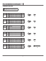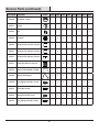
1
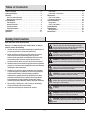
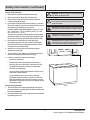
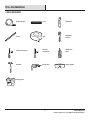
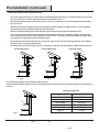
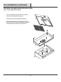
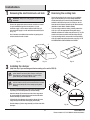
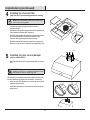
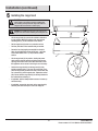
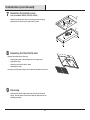
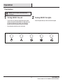
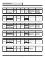
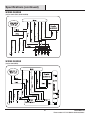
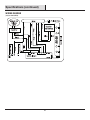
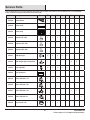
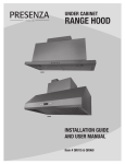
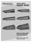
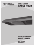
UNDER CABINET
RANGE HOOD
INSTALLATION GUIDE
AND USER MANUAL
Item # QR001, QR003, QR006
QR009, QR014 & QR019
Table of Contents
Table of Contents . . . . . . . . . . . . . . . . . . . . . . . . . . . . . 2
Safety Information. . . . . . . . . . . . . . . . . . . . . . . . . . . . . 2
Warranty . . . . . . . . . . . . . . . . . . . . . . . . . . . . . . . . . . . 4
One Year Limited Warranty. . . . . . . . . . . . . . . . . . . . . . . . . . . . 4
Warranty Claim Procedure. . . . . . . . . . . . . . . . . . . . . . . . . . . . 4
Pre-Installation. . . . . . . . . . . . . . . . . . . . . . . . . . . . . . . 5
Tools Required. . . . . . . . . . . . . . . . . . . . . . . . . . . . . . . . . . . . . 5
Hardware Included. . . . . . . . . . . . . . . . . . . . . . . . . . . . . . . . . . 6
Package Contents . . . . . . . . . . . . . . . . . . . . . . . . . . . . . . . . . . 7
Planning Installation . . . . . . . . . . . . . . . . . . . . . . . . . . . . . . . . 8
Installation. . . . . . . . . . . . . . . . . . . . . . . . . . . . . . . . . 13
Operation. . . . . . . . . . . . . . . . . . . . . . . . . . . . . . . . . . 17
Push Button. . . . . . . . . . . . . . . . . . . . . . . . . . . . . . . . . . . . . . 17
Push Button / LCD Screen . . . . . . . . . . . . . . . . . . . . . . . . . . . 18
Maintenance . . . . . . . . . . . . . . . . . . . . . . . . . . . . . . . 19
Filters / Baffle Nets . . . . . . . . . . . . . . . . . . . . . . . . . . . . . . . . 19
Replacing Light Bulbs . . . . . . . . . . . . . . . . . . . . . . . . . . . . . . 19
Care and Cleaning. . . . . . . . . . . . . . . . . . . . . . . . . . . . 20
Range Hood. . . . . . . . . . . . . . . . . . . . . . . . . . . . . . . . . . . . . . 20
Filters / Baffle Nets . . . . . . . . . . . . . . . . . . . . . . . . . . . . . . . . 20
Troubleshooting . . . . . . . . . . . . . . . . . . . . . . . . . . . . . 21
Specifications. . . . . . . . . . . . . . . . . . . . . . . . . . . . . . . 22
Wiring Diagram . . . . . . . . . . . . . . . . . . . . . . . . . . . . . . . . . . . 23
Service Parts . . . . . . . . . . . . . . . . . . . . . . . . . . . . . . . 25
Safety Information
READ AND SAVE THESE INSTRUCTIONS
Warning - To reduce the risk of fire, electric shock, or injury to
persons, observe the following:
1. Use this unit only in the manner intended by the manufacturer. If
you have any questions, contact the manufacturer.
2. Before servicing or cleaning unit, switch power off at service
panel and lock service disconnecting means to prevent
power from being switched on accidentally. When the service
disconnecting means cannot be locked, securely fasten a
prominent warning device, such as a tag, to the service panel.
3. Installation work and electrical wiring must be done by qualified
person(s) in accordance with all applicable codes and standards,
including fire-rated construction.
4. Sufficient air is needed for proper combustion and exhausting
of gases through the flue (chimney) of fuel burning equipment
to prevent back drafting. Follow the heating equipment
manufacturer’s guideline and safety standards such as those
published by the National Fire Protection Association (NFPA),
and the American Society for Heating, Refrigeration and Air
Conditioning Engineers (ASHRAE), and the local code authorities.
5. When cutting or drilling into a wall or ceiling, do not damage
electrical wiring and other hidden utilities.
6. Ducted fans must always be vented to the outdoors.
DANGER: Turn off the power circuit breaker or the power
switch on the junction box before installing or servicing
this unit. Touching circuitry inside the range hood while it is
energized will result in death or serious injury.
DANGER: All electrical wiring must be properly installed,
insulated, and grounded. Improper insulation and grounding
will result in deadly electrical shock.
DANGER: If installing this unit over a gas range, turn off
the gas at the source before installing or servicing this unit.
WARNING: Attempting to install or service this unit
when you do not have the necessary technical or electrical
background could result in personal injury.
WARNING: The unit has sharp edges. Always wear safety
gloves during installation, cleaning, or servicing.
WARNING: Always leave safety grills and filters in place.
Without these components, operating fans could catch on to
hair, fingers, or loose clothing.
WARNING: Stay clear of the rotating fan when the motor
is running.
WARNING: Keep this appliance clean and free of grease
and residue build-up at all times to prevent fires.
CAUTION: This device is for general ventilating use only.
Do not use to exhaust hazardous or explosive materials and
vapors.
2
Safety Information (continued)
Cooking Safety Information
WARNING: To reduce the risk of fire, use only metal duct
1. Never leave the range hood unattended when in use.
work. Never use plastic duct work.
2. Never cook over open flames under the range hood.
3. Always turn the range hood on when cooking at high heat
or when cooking flaming foods.
WARNING: To reduce the risk of fire or electric shock, do
not use this range hood with with any external solid state
speed control device.
4. If you choose to hang the range hood as below (Fig. 1) distance
(D) from the cooktop surface, use extra caution as the surface of
range hood may be extremely hot to the touch.
For QR001, QR003, QR006, QR009 & QR014, (D in Fig. 1) is 458
mm - 710 mm (18 in. - 28 in.). For QR019, (D in Fig. 1) is 432
mm - 813 mm (17 in. - 32 in.).
The closer you install to the cooktop (within the recommended
distances) the hotter the range hoods surface temperature will
become when cooking for an extended period amount of time.
CAUTION: For general ventilation use only. Do not use the
range hood fans to exhaust hazardous or explosive vapours.
CAUTION: Never dispose of cigarette ashes, ignitable
substances, or any foreign objects in fans.
CAUTION: At least two people are needed to move and
safely install the unit. Failure to properly lift the range hood
could result in product damage or personal injury.
5. Use caution when cooking with oil or with deep-fryers.
Overheating may cause oil to reach its flash point and ignite.
Used oil will ignite at lower temperatures than fresh oil. Heat
oils slowly on low to medium setting.
6. Avoid boil overs, as they may cause smoking and greasy
spillovers that could ignite.
7. To prevent burns or fires, always use cookware appropriate to
the size of the heating element that you are using.
8. In event of a cooking fire, observe the following:
D
-- Be careful to avoid burns.
-- Smother flames with a close-fitting lid, cookie sheet, or
metal tray, then turn off the burner. If the flames do not go
out immediately, evacuate and call the fire department.
-- Never pick up a flaming pan.
-- Do not use water, including wet dishcloths or towels, as you
could cause a steam explosion.
-- Use an extinguisher only if: (a) you have a class ABC
extinguisher and you know how to operate it, (b) the fire is
small and contained in the area where it started, (c) the fire
department is being called, and (d) you can fight the fire with
your back to the exit.
Cleaning Safety Information
Fig. 1
1. The fan and filters must be cleaned periodically and kept free
from accumulation of cooking residue. Old and worn filters must
be replaced immediately.
2. Never disassemble parts to clean. Parts should be disassembled
by qualified persons only.
3
CONGLOMKB.COM
Please contact 1-877-333-0098 for further assistance.
Warranty
ONE YEAR LIMITED WARRANTY
A thorough inspection must be made before installation and any damage must be promptly reported. We will not be liable for failures or
damage that could have been discovered or avoided by proper inspection and testing prior to installation.
Conglom Kitchen & Bath warrants this product to be free from defects in materials or workmanship for one (1) year from the date of purchase.
Proof of purchase (original sales receipt) from the original consumer purchaser must be made available to Conglom Kitchen & Bath for all
warranty claims.
This warranty is non-transferable and shall be voided if the unit is removed from its initial installation or if it is not installed following the
manufacturer’s instructions. It does not apply in the event of product damage due to the use of other than genuine Conglom Kitchen & Bath
replacement parts, (Replacement parts may be obtained by calling 1-877-333-0098 between 8:30 am - 5:00 pm EST) installation error, abuse,
misuse or improper care and maintenance (whether performed by a plumber, contractor, service provider or member of the purchaser’s
household). The warranty excludes damage due to aggressive air or water conditions, harsh or abrasive cleaners and/or materials.
Under no circumstance shall we be held liable for personal injury or property damage resulting from improper installation or use of this
product. We will not be held liable for inconvenience caused by loss of use of this product, costs incurred for labour or materials, removal
and installation of replacement units, or any other incidental or consequential damages. Costs relating to obtaining access for repair or
replacement are the responsibility of the user.
Our obligation shall be limited to the repair or replacement of a unit (at our discretion) that may prove, by our sole examination, to be defective
under normal use and service during the warranty period.
Any failure of this product that is not traceable to a defect in material or workmanship is not covered by this warranty. These non-warrantable
items include, but are not limited to:
-- Improper installation not in accordance with manufacturer’s instructions.
-- Dents and/or scratches incurred during shipping, handling, or installation.
-- Change in colour or finish due to chemical usage.
-- Damage caused by failure to follow care and cleaning guidelines, including damage caused by the use of abrasive cleaners.
-- Alterations made to the unit by the purchaser or installer.
-- Damage caused by accidental impact, fire, flood, freezing, and normal wear.
-- Bends and warping caused by forced connections, over-tightened fittings, and inadequate support during installation.
-- Any defects or damage to light bulbs.
This warranty does not extend to commercial and institutional installation or use.
WARRANTY CLAIM PROCEDURE
If a claimable defect occurs or replacement parts are needed, please contact our customer service team at 1-877-333-0098 (8:30 am - 5 pm,
EST, Monday–Friday).
Before you make your call, please ensure that you have:
-- Model number or description of the range hood.
-- Proof of sale.
-- Details regarding the defect and/or part number.
-- Name(s) and address(es) of the owner and installer.
4
Pre-Installation
TOOLS REQUIRED
Measuring tape
Level
Utility knife
Pencil
Tape
Adjustable
wrench
Phillips screwdriver
Flathead
screwdriver
Needle nose
pliers
Hammer
Electric drill
Safety goggles
Safety gloves
5
CONGLOMKB.COM
Please contact 1-877-333-0098 for further assistance.
Pre-Installation (continued)
HARDWARE INCLUDED
NOTE: Hardware not shown to actual size.
Model
QR001
Model
QR003
Model
QR006
Model
QR009
Model
QR014
Model
QR019
Part
Description
Quantity
AA
Long tapping screw - (M5 mm x 12 mm)
4
BB
Short tapping screw - (M4 mm x 8 mm)
2
Part
Description
BB
AA
BB
AA
BB
AA
BB
AA
BB
Quantity
AA
Long tapping screw - (M5 mm x 12 mm)
4
BB
Short tapping screw - (M4 mm x 8 mm)
2
Part
Description
Quantity
AA
Long tapping screw - (M5 mm x 12 mm)
4
BB
Short tapping screw - (M4 mm x 8 mm)
2
Part
Description
Quantity
AA
Long tapping screw - (M5 mm x 12 mm)
4
BB
Short tapping screw - (M4 mm x 8 mm)
2
Part
Description
Quantity
AA
Long tapping screw - (M5 mm x 12 mm)
4
BB
Short tapping screw - (M4 mm x 8 mm)
2
Part
Description
Quantity
AA
Long tapping screw - (M5 mm x 12 mm)
4
CC
Short tapping screw - (M4 mm x 16 mm)
6
6
AA
AA
CC
Pre-Installation (continued)
PACKAGE CONTENTS
A
B
D
C
F
E
Model
QR001
Model
QR006
Model
QR014
I
H
G
Part
Description
Quantity
A
Range Hood
1
G
Charcoal Filter
1
H
Damper
1
Part
Description
Quantity
C
Range Hood
1
G
Charcoal Filter
1
H
Damper
1
Part
Description
Quantity
E
Range Hood
1
H
Damper
1
Model
QR003
Model
QR009
Model
QR019
Part
Description
Quantity
B
Range Hood
1
G
Charcoal Filter
1
H
Damper
1
Part
Description
Quantity
D
Range Hood
1
H
Damper
1
Part
Description
Quantity
F
Range Hood
1
I
Duct Set
1
7
CONGLOMKB.COM
Please contact 1-877-333-0098 for further assistance.
Pre-Installation (continued)
PLANNING INSTALLATION
Number of people required: 2 or more
WARNING: Always wear safety goggles and gloves during
Carefully check the range hood for damage and for missing parts prior
to installation. If there is any damage or if you are missing parts, do
not proceed with the installation. Report damage and missing parts
immediately. Do not dispose of packaging before you are satisfied with
your new range hood.
installation.
1. Before installation, measure all distances to ensure the proper
position of the range hood (A).
-- The distance (1) from the cooking surface to the range hood
must be at least 18 in. (458 mm), for QR019 the minimum
distance is 17 in. (432 mm). For the best performance, do not
install the range hood more than 28 in. (710 mm) and no more
than 32 in. (813 mm) for the QR019 above the cooking surface.
7
7
4
3
A
1
6
3
7
-- Dimension (3) should be at least 30” (762 mm). The range hood
should be approximately the same size as the cooktop.
2. If the bottom of the cabinet (6) above the location where the range
hood is to be installed is recessed, attach appropriately sized wood
filler strips (7) on each side using wood screws.
3. Screws are provided to secure the range hood to most types of
cabinets, but consult a qualified installer to verify that the supplied
screws are suitable for your cabinets.
4. Put a thick, protective covering over your counter, cooktop, or range
to protect it from damage and dirt during installation. Remove any
hazardous objects around the area.
Fig. 2
Venting Options (QR001, QR003 & QR006):
a. Determine if your existing venting system is top venting or back venting, and ensure that the openings in the cabinet or wall for the
damper and for power access are in appropriate locations and are of appropriate sizes, as per Fig. 3 if it is top vent or Fig. 4 if it is
back vent.
b. If this is a new installation, choose the venting method that suits your needs. Cut out openings for the damper and for power access
in the cabinet bottom or exterior wall, depending on the direction of venting chosen.
10-1/4”
260
Fig.3
8
10-1/4”
260
Fig.4
Pre-Installation (continued)
Venting Options (QR001, QR003 & QR006):
a. Determine if your existing venting system is top venting or back venting, and ensure that the openings in the cabinet or wall for the
damper and for power access are in appropriate locations and are of appropriate sizes, as per Fig. 5 if it is top vent or Fig. 6 if it is
back vent.
b. If this is a new installation, choose the venting method that suits your needs. Cut out openings for the damper and for power access
in the cabinet bottom or exterior wall. Following Fig. 5 if it is going to be a top vent or Fig. 6 if it is going to be a back vent.
11.25”
(285mm)
10-1/4 ”
(260mm)
10-1/4 ”
(260mm)
Fig. 5
11.25”
(285mm)
Fig. 6
Venting Option (QR019):
You must use a top venting system that vents to the outdoors.
a. If using an existing venting system, ensure that the openings in the cabinet bottom for the damper and for power access are in
appropriate locations and are of appropriate sizes, see Fig. 7.
b. If this is a new installation, cut out openings for the damper and for power access in the cabinet bottom, see Fig. 7.
3/4” Dia
(20mm)
9”
(228.5mm)
7-5/8”
(195mm)
7-1/4”
(180mm)
10-5/8”
(270mm)
Fig.7
9
CONGLOMKB.COM
Please contact 1-877-333-0098 for further assistance.
Pre-Installation (continued)
Follow these guidelines when installing duct work:
-- Your venting system must vent to the outdoors either horizontally through the back wall (13) or vertically through the roof (14) (refer
to Fig. 8/Fig. 9/Fig. 10). For interior venting (the air does not vent outdoors), see Fig. 11.
-- Use round metal duct work with a uniform diameter of 6 in. (152 mm). The total duct run in the venting system should be not more
than 10.7 m (35 ft).
-- Calculate the total effective length of the duct work by adding the equivalent lengths in the table shown (Fig. 12). For each fitting
used add the length of the equivalent straight duct used in the system.
-- Fasten all connections between pieces of duct with sheet metal screws and tape all joints with certified duct tape.
-- If you must turn the path of the duct work using elbows, keep the number of elbows to a minimum for effective performance and
use no more than three 90° elbows. Ensure that there is a minimum of 18 in. (458 mm) of straight vent between each elbow. Elbow
as far away from the range hood’s exhaust opening as possible.
-- Cap the exterior of the duct with a wall cap (15) or roof cap (16). Never use 4 in. (102 mm) laundry-type wall caps. Use caulking to
seal exterior wall or roof opening around the cap.
-- The venting system must have a damper. If the roof or wall cap has a damper, do not use the damper supplied with the range hood.
Horizontal Wall Venting
Horizontal Wall Venting
Vertical Roof Venting
16
14
15
15
13
Fig.8
13
Fig. 9
Fig. 10
For inside venting system (air does not exhaust to outdoors) (Fig. 8):
Please refer to the Installation section. The cover on the top plate will be removed and air will be exhausted through the charcoal filter and
out from 17.
Equivalent Length Chart
17
Fig 11.
Type of duct
Length added
45° Elbow
3 ft. (0.91 m)
90° Elbow
5 ft (1.52 m)
90° Flat elbow
12 ft (3.66 m)
2 x 90° Elbow
10 ft (3.05 m)
9 ft (2.74 m) Straight duct
9 ft (2.74 m)
Wall cap
0 ft (0 m)
Fig. 12
10
Fig. 8
Fig. 9
Pre-Installation (continued)
WIRING CONNECTION REQUIREMENTS
Installation work and electrical wiring must be done by a qualified
person(s) in accordance with all applicable codes and standards,
including fire-rated construction.
OBSERVE ALL GOVERNING CODES AND ORDINANCES WARNINGS
-- Electrical grounding is required for this range hood. Check
with a qualified electrician if you are not sure whether the
range hood is properly grounded.
-- Failure to follow electrical requirements may result in a
fire.
-- A fuse in the neutral or grounding circuit could result in
electrical shock.
-- If the hot/cold water pipe is interrupted by plastic
nonmetallic gaskets or other materials, DO NOT use for
grounding.
-- DO NOT GROUND TO A GAS PIPE.
IMPORTANT: It is the customer’s responsibility to contact a qualified
electrical installer and assure that the electrical installation is
adequate and complies with the National Electrical Code, or CSA
standards, as well as all local codes and ordinances.
3. Save installation instructions for electrical inspector’s use.
4. If codes permit and a separate ground wire is used, it is
recommended that a qualified electrician determine if the
ground path is adequate.
5. DO NOT use an extension cord or adapter plug with this
appliance.
6. The range hood must be connected with copper wire only.
7. The range hood should be connected directly to the junction
(or circuit breaker) box through flexible, armoured or
nonmetallic sheathed copper cable. Allow some slack in the
cable so the
appliance can be moved if servicing is ever necessary.
8. A UL listed or CSA approved conduit connector must be
provided at each end of the power supply cable (at the range
hood and at
the junction box).
9. When making the electrical connection, cut a 3.2 cm (1-1/4 in.
hole in the wall. A hole cut through wood must be sanded until
smooth. A hole through metal must have a grommet.
DANGER: Risk of electrical shock. This range hood must
be properly grounded.
DANGER: Turn off the power circuit breaker or the
power switch on the junction box before installing this
unit. Touching circuitry inside the range hood while it is
energized will result in death or serious injury.
DANGER: All electrical wiring must be properly installed,
insulated, and grounded. Improper insulation and grounding
will result in deadly electrical shock.
NOTE: Temporarily wire the range hood to test it for proper
operation. If the range hood does not operate correctly, do
not proceed with the installation.
-- Use the power supply cable to connect the range hood (A)
directly to the junction box or circuit breaker box. Use a
flexible, armoured, or nonmetallic sheathed copper cable
only. Never use an extension cord or adapter plug.
-- Connect a UL-listed or CSA-approved conduit connector
to each end of the power supply cable (at the range hood
and at the junction box). Connect the three colored wires
(3) from the range hood (A) to the corresponding wires (4)
from the electrical source: black to black (live), white to
white (neutral), and green/yellow to green/yellow (ground).
Use either the top hole (1) or the back hole (2) of the range
hood depending on your installation type.
-- Turn the power on, and ensure that the lights and the fan
are operating correctly.
-- Once you have tested the electrical connection, disconnect
the power supply cable and wires from the electrical
source before proceeding with the rest of the installation.
A
4
1
3
2
10. When cutting or drilling into the wall or ceilling, do not
damage
electrical wiring and other hidden utilities.
11. Wire size must conform to all local codes and ordinances.
The latest edition requirements of the National Electrical Code
ANSI/NFPA 70, or the latest edition CSA Standards C22.1-94,
Canadian Electrical Code Part 1 and C22.2 No. 0-M91.
11
CONGLOMKB.COM
Please contact 1-877-333-0098 for further assistance.
Pre-Installation (continued)
PREPARING THE RANGE HOOD FOR INSTALLATION
(only for models QR009, QR014 & QR019)
-- Turn over the range hood (A) and place it on a protective
surface, such as cardboard or a large towel.
-- Remove the baffle nets (1) by pulling the handles (2).
A
1
-- Remove the bottom panel (3) by removing the six screws
(CC). Ensure you have a good grip on the bottom panel when
removing the screws so they do not fall into the unit.
1
CC
3
A
12
2
Installation
1 Removing the electrical knock-out hole 2 Removing the venting hole
-- Choose the venting hole to remove for your installation
type. Use the top hole (3) for a top venting installation
and the back hole (4) for a back venting installation (not
available in QR019) and top hole 5 for when you do not
have the exterior exhaust, but will use the interior feature
(available in units QR001, QR003 & QR006).
WARNING: Always wear safety goggles and gloves during
installation.
-- Choose the appropriate electrical knock-out hole to remove
for your installation type. Use the top hole (1) if your
electrical supply is in the cabinet and the back hole (2) if
your electrical supply is on the wall below the cabinet (refer
to Fig. 13).
-- If you are using an exterior venting, carefully remove the
cover (3 or 4) for the appropriate venting hole using a
flathead screwdriver or needle nose pliers (see Fig. 14). Be
careful not to leave any debris inside the range hood (A).
-- Use a hammer and a flathead screwdriver to gently punch
out the electrical knock-out hole.
-- If you are venting indoors, unscrew the 2 screws holding
cover (5) in place and remove the cover as per Fig. 15. DO
NOT REMOVE ANY OTHER VENTING HOLE COVER.
5
1
A
3
A
5
2
4
A
Fig. 13
Fig. 14
Fig. 15
3 Installing the damper
(skip this step if you are using an interior venting or the unit is QR019)
NOTICE: Only install the damper if you are using a venting
system that does not already have a damper. If using the
charcoal filter for ductless installation, or if your venting
system already has a damper, skip this step.
A
8
NOTICE: If this hood replaces an existing unit, the location
of the air exhaust can vary from one manufacturer to another.
Ensure that the damper fits in the existing opening before
installing.
-- Choose to install the damper (C) either in the top position (3 for
top venting or in the back position (4) for back venting.
BB
A
8
4
BB
BB
3
C
7
-- Insert the damper (C) into the chosen hole in the range hood
(A), ensuring that the central flap (6) goes into the hole while
the two side flaps (7) remain above it.
-- Lift the lid (8) of the damper and screw the damper (C) to the
range hood (A) with the two short tapping screws (BB).
-- Seal the damper (C) to the range hood (A) on all four sides with
duct tape.
13
C
6
7
C
Fig. 16
CONGLOMKB.COM
Please contact 1-877-333-0098 for further assistance.
Installation (continued)
4
Installing the charcoal filter
(skip this step if you are using an exterior venting)
NOTICE: The charcoal filter should only be installed if you
are not using a venting system.
10
-- Turn over the range hood (A) and place its top on a
protective surface.
9
-- Unhook the charcoal filter support (9) from the support hook
(10) and pull the charcoal filter support up.
10
-- Place the charcoal filter (B) under the charcoal filter support
(9). Ensure that the filter is placed horizontally, or the
charcoal filter support (9) will not close properly.
11
9
11
-- Slide the charcoal filter support (9) to the left or right in its
braces (11) until you can re-hook it on its support hook (10).
CC
5
B
Installing the duct set and damper
(only for model QR019)
A
-- Attach the duct set (B) to the range hood (A) with six screws
(CC).
CAUTION: Be very careful when installing the damper.
Applying too much force or not bending the damper enough
may damage or break the damper hinge ends.
The damper is pre-installed at the factory. Make sure that it has
not come loose during shipping and re-install it, if necessary.
-- Insert one end of the damper (1) into the hinge slot (2) at the
top of the range hood (A).
-- Gently bend the damper (1) and insert its other end into the
hinge slot (2).
1
2
A
14
1s
Installation (continued)
6 Installing the range hood
DANGER: Turn off the power circuit breaker or the
power switch on the junction box before installing this
unit. Touching circuitry inside the range hood while it is
energized will result in death or serious injury.
DANGER: If installing this unit over a gas range, turn off
the gas at the source before installing or servicing this unit.
AA
AA
-- Lift the range hood (A) up under the cabinet to determine
its final position. Mark the location of the four keyhole
mounting slots (1) on the underside of the cabinet.
1
1
-- Set the range hood (A) aside on a protective surface.
-- Drill four pilot holes in the locations that you marked.
-- Screw the four long tapping screws (AA) into the pilot
holes. Do not tighten the screws all the way – leave the
screw heads about 0.28 in. (7 mm) from the cabinet
surface.
-- Lift the range hood (A) into position, feeding the power
cable and the electrical wires through the power access
opening. Allow some slack in the cable and wires so that
the appliance can be moved if servicing is ever necessary.
-- Position the range hood (A) so the large end (2) of the
keyhole mounting slots (1) are over the screws (AA). Then
push the range hood (A) toward the wall so the screws (AA)
are in the neck (3) of the keyhole slots. Tighten the screws
(AA). Ensure that the range hood (A) is securely fastened to
the cabinet before releasing it.
A
AA
2
1
3
-- If applicable, test the damper blade to ensure it rotates up
and down freely.
-- If applicable, connect the duct work to the range hood (A).
Seal the joints with duct tape to ensure an airtight fit.
15
CONGLOMKB.COM
Please contact 1-877-333-0098 for further assistance.
Installation (continued)
7
Replacing the bottom panel
(only for models QR009, QR014 & QR019)
A
-- Replace the bottom pane (B) on to the range hood body (A) by
putting back the 6 screws (CC) that hold it in place.
B
CC
8 Replacing the filter/baffle nets
Replace the baffle nets or filters by:
-- Inserting them first in the back groove of the range hood.
-- Opening the clasp.
-- Putting the front of the filter in place.
-- Releasing the clasp.
Keep your hand in place until you are certain that the filters are secure.
9 Final step
-- Reconnect the power supply cable and wires to the electrical
supply. Turn the power on and ensure that the lights and fan are
operating correctly.
16
A
3
2
1
Operation
Push button
NOTICE: The fan and lights operate independently
of each other.
1 Turning ON/OFF the unit
-- To turn on the fan, press the appropriate speed control
switch [Low Speed (2), Medium Speed (3), High Speed (4)]
to select the desired level of power. Once a button is
pressed, the previous speed mode will be cancelled.
2 Turning ON/OFF the lights
-- Press the light switch (5) to turn on and off the lights.
-- Press the power switch (1) to turn off the fan.
1
2
3
17
4
5
CONGLOMKB.COM
Please contact 1-877-333-0098 for further assistance.
Operation (continued)
Push button / LCD Screen
There are four buttons, ON/OFF, SPEED, LIGHT and CLOCK SETUP.
The center screen will show the clock (12 hour).
1
2
3
1 Turning ON/OFF the unit
-- Press (5) to turn on the power.
When you turn the power on, the unit starts working in high
speed, the clock indication on the center screen (3) will
go off and "3" will be indicated on the screen. (During the
operation speed indication will be indicated on the screen).
-- Press (5) twice to turn off the unit while it is operating.
While the fan is off, the screen will display the time.
4
5
2 Delay shut off function
-- While the fan is working, press (5) once, the fan and lights
will automatically turn off after 2 minutes.
The screen will indicate "2:00" and start counting down.
Once the countdown is completed, the range hood will
beep, the fan and lights will turn off automatically and the
clock will show in the screen.
During the countdown operation:
-- You will still be able to change the speed by pressing (4).
-- Press (5) once more to stop the fan immediately.
3 To change fan speed
While the unit is operating:
4 Turning ON/OFF the light
-- Press the light button (2) to turn the light on and off.
-- Press the fan button (4) once, range hood will change to
medium speed and "2" will be indicated on the screen.
-- Press the fan button (4) again to change to low speed and
"1" will show on the screen.
5 Set up the clock function
-- Press the clock button (1) once, the center screen starts flashing "88:88".
-- Press the light button (2) to change the hour display and the fan button (4)
to change the minute display.
-- During the setup, if no button is pressed for more than 5 seconds, the setting
displayed will be fixed. The setup can be done while the unit is running or not.
18
Maintenance
DANGER: Turn off the power circuit breaker or the power
switch on the junction box before performing maintenance.
Touching circuitry inside the range hood while it is
energized will result in death or serious injury.
WARNING: Failure to replace worn out or damaged filters
will increase the risk of fire.
WARNING: Light bulbs can become extremely hot when
turned on. Do not touch bulbs until they are switched off
and cooled. Touching hot bulbs could cause serious burns.
FILTERS/BAFFLE NETS
When filters or baffle nets need replacing, exchange with similar
filters or baffle nets with stainless steel clips. Also replace filters
or baffle nets that are damaged with punctures, bends, or broken
frames.
-- Turn off the range hood and disconnect the power.
-- Replace with an equivalent filter or baffle net, then
reconnect the power.
For JDR16, GU10 twist
and lock base light bulb
REPLACING LIGHT BULBS
When light bulbs burn out, replace them with the correct light bulb
(as per the specifications on page 22).
-- Turn off the range hood, disconnect it from its power
source, and ensure that the lights are cool.
For Type JC
halogen bulbs
-- Remove the old bulb and install the new one. Do not release
the bulb until you are sure the bulb has been securely
installed. Then reconnect the power.
-- If new bulbs do not operate, ensure that they are inserted
correctly.
1
Remove
2
Remove
Replace
Replace
19
CONGLOMKB.COM
Please contact 1-877-333-0098 for further assistance.
Care and Cleaning
RANGE HOOD
WARNING: Failure to maintain basic standards of care
and cleaning of the range hood will increase the risk of fire.
The range hood should be cleaned (regularly internally and externally) to preserve its appearance and performance.
Do:
-- Always clean in the direction of the grain (original
polish lines).
-- Clean the range hood periodically with hot, soapy
water and a clean cotton cloth.
Do Not:
-- Do not use corrosive or abrasive detergents, steel
wool, or scouring pads. These will scratch and
damage the stainless steel surface.
-- Always rinse well with clean water two or three
times after cleaning. Wipe completely dry with a
soft non-abrasive cloth.
-- Do not use corrosive or abrasive detergents, or any
products containing chloride, fluoride, iodide, or
bromide on this product, as they will deteriorate
the surface rapidly.
-- After cleaning, you may polish with a non-abrasive
stainless steel polish or cleaner. Always rub lightly
and with the grain.
-- Do not allow cleaning compounds, salt solutions,
disinfectants, or bleaches to remain in contact with
the product for extended periods of time.
-- Ensure that the venting system is free of debris, if
you have one.
-- Do not allow deposits to remain for long periods
of time on the range hood. Rinse with water
immediately and wipe dry with a clean cloth.
-- Do not let plaster dust or any other construction
residue enter the hood. During construction or
renovation, cover the hood.
-- Combustible products used for cleaning such as
acetone, alcohol, ether, or benzol are highly explosive
and should never be used close to a range or stove.
FILTERS/BAFFLE NETS
The filters fitted by the factory is intended to filter out residue and grease from cooking. You do not need to replace them on a regular basis,
but you should keep them clean.
Do:
-- Clean the filters/baffle nets once a month using
non-abrasive detergents, either by hand or in
the dishwasher. When using a dishwasher, set
the dishwasher to a low temperature and a short
cycle setting. The filter may become discoloured
in a dishwasher, but this does not affect its
performance.
-- Dry the filters/baffle nets before re-installing them
in the range hood.
20
Do Not:
-- Do not allow oil to accumulate over more than 80%
of the filter surface. Oil accumulations may drip oil
onto the range.
-- Do not wash charcoal filters. Charcoal filters should
be replaced when they are covered in grease and
have reached their maximum absorbance.
Troubleshooting
DANGER: Turn off the power circuit breaker or the power switch on the junction box before performing maintenance.
Touching circuitry inside the range hood while it is energized will result in death or serious injury.
Problem
Solution
The range hood will not operate.
-- Check that the power supply cable and all electrical wiring are properly
connected.
-- Check that the power is turned on at the junction box or circuit breaker.
-- Check that the wiring between the switch control and the control board are
connected properly.
The range hood vibrates when the fan is operating.
-- Check that the range hood has been secured properly to the wall. Tighten into
position, if necessary.
-- Check that the motor is secured in place. If not, then tighten the motor in place.
-- Check that the fan is not damaged. If so, replace the fan.
The fans seem weak.
-- Check that the duct size used is at least 6 in. (152 mm) round. The range hood
will not function efficiently with insufficient duct size.
-- Check that the duct is not clogged with debris and the tight mesh on the wall
cap, if applicable, isn’t restricting air flow.
-- Check that the damper unit is opening properly.
-- Check that no birds or animals have nested in the duct.
The lights work, but the fan is not spinning, is stuck,
or is rattling.
-- The thermal protection system detects if the motor is too hot to operate and
shuts the motor down. In this case, the motor will function properly after the
thermal protection system cools down (after approximately 10 min.).
-- Check that the fan isn’t jammed or scraping the bottom.
-- If nothing else works, the motor may be defective or seized. If so, replace the
motor.
The range hood is not venting properly.
-- Check that no birds or animals have nested in the duct.
-- Check that the distance between the cooktop and the bottom of the range hood
is within its models requirements (see page 8).
-- Check that duct work follows all requirements. Use round metal duct work with
a uniform diameter of 6 in. (152 mm). The length of duct work must not exceed
35 ft (10.7 m). Reduce the length of duct work and the number of elbows if
necessary. Ensure that all joints are properly connected, sealed, and taped.
-- Check that the duct does not open against the wind.
-- Ensure that the power is on high speed for heavy cooking.
-- Wind from opened windows or doors may affect the performance of the range
hood. Close all windows and doors to eliminate outside air flow.
-- To enhance the performance of the range hood, open slightly a window on the
opposite side of the house where the range hood vents outdoors.
A light does not work.
-- Check to see if light bulb is burnt. If so, replace.
-- Check the light bulb to see if it is loose. If so, tighten.
-- Remove the problem bulb and insert one you know is working. If the properly
functioning light does not come on, the problem may be the light assembly.
Have the light assembly serviced or replaced.
21
CONGLOMKB.COM
Please contact 1-877-333-0098 for further assistance.
Specifications
Model
Dimensions
29.8 in. (757 mm) W
QR001
18 in. (458 mm) D
Rating
120~60Hz
1.6A
Control Type Fan CFM
Push Button
5 in. (127 mm) H
Model
Dimensions
29.8 in. (757 mm) W
QR003
18 in. (458 mm) D
Rating
120~60Hz
1.6A
Control Type Fan CFM
Push Button
5 in. (127 mm) H
Model
Dimensions
29.8 in. (757 mm) W
QR006
18 in. (458 mm) D
Rating
120~60Hz
1.6A
Dimensions
29.8 in. (757 mm) W
QR009
18 in. (458 mm) D
Rating
120~60Hz
1.5A
Push Button
Dimensions
29.8 in. (757 mm) W
QR014
18 in. (458 mm) D
Rating
120~60Hz
1.5A
Push Button
Dimensions
29.8 in. (757 mm) W
QR019
18 in. (458 mm) D
12 in. (127 mm) H
Rating
320 ±
10%
Control Type Fan CFM
Push Button
9 in. (127 mm) H
Model
275 ±
10%
Control Type Fan CFM
7 in. (178 mm) H
Model
300 ±
10%
Control Type Fan CFM
6 in. (152 mm) H
Model
300 ±
10%
320 ±
10%
Control Type Fan CFM
120~60Hz Push Button
2A
/ LCD Screen
500 ±
10%
22
Speeds
Light Bulb Wattage
Venting Options
High
Low
2 x Max. 25W or
35W/JDR 16, GU10
twist and lock base
light bulb
Top venting
Back venting
Recirculating
Inside venting
Speeds
Light Bulb Wattage
Venting Options
High
Low
2 x Max. 25W or
35W/JDR 16, GU10
twist and lock base
light bulb
Top venting
Back venting
Recirculating
Inside venting
Speeds
Light Bulb Wattage
Venting Options
High
Low
2 x Max. 25W or
35W/JDR 16, GU10
twist and lock base
light bulb
Top venting
Back venting
Recirculating
Inside venting
Speeds
Light Bulb Wattage
Venting Options
High
Top venting
Back venting
Low
2 x Max. 25W or
35W/JDR 16, GU10
twist and lock base
light bulb
Speeds
Light Bulb Wattage
Venting Options
High
Top venting
Back venting
Low
2 x Max. 25W or
35W/JDR 16, GU10
twist and lock base
light bulb
Speeds
Light Bulb Wattage
Venting Options
2 x Max. 20W /
12 V, Type JC
Top venting
Medium
Medium
Medium
Medium
Medium
High
Medium
Low
Specifications (continued)
WIRING DIAGRAM
(only for models QR001, QR003 & QR009)
WIRING DIAGRAM
(only for model QR014)
23
CONGLOMKB.COM
Please contact 1-877-333-0098 for further assistance.
Specifications (continued)
WIRING DIAGRAM
(only for model QR019)
24
Service Parts
If you are missing parts or if you require replacement parts, please call our customer service team at 1-877-333-0098 (8:30 am – 5 pm, EST, Monday–
Friday). Identify the required part(s) and have the part number(s) ready.
Part Number Description
Picture
QR001 QR003 QR006 QR009 QR014 QR015 QR019 QR060
QHR106
Control Switch
1
1
1
1
-
1
-
-
QHR105
Control Panel
-
-
-
-
1
-
1
1
QHR104
Control Panel
-
-
-
-
1
-
1
1
QHR100
Capacitor 5UF, 370V
1
1
1
1
1
-
-
-
QHR102
Capacitor 10UF, 370V
-
-
-
-
-
1
1
-
QHR103
Capacitor 20UF, 330V
-
-
-
-
-
-
-
1
QHR121
35W GU10 Light
2
2
2
2
2
-
-
2
QHR122
20W Halogen Light and Light Base
-
-
-
-
-
2
2
-
QHR123
GU10 Light Base
2
2
2
2
2
-
-
2
QHR124
Light Transformer
-
-
-
-
-
1
1
-
QHR126
Motor 120V, 60Hz, 1.1A
1
1
1
-
-
-
-
-
QHR125
Motor 120V, 60Hz, 1.0A
-
-
-
1
1
-
-
-
QHR127
Motor 120V, 60Hz, 1.5A
-
-
-
-
-
1
1
-
QHR128
Motor 120V, 60Hz, 3A
-
-
-
-
-
-
-
1
QHR108
Fan (77.3mm / 3in)
1
1
1
-
-
-
-
[...]
25
CONGLOMKB.COM
Please contact 1-877-333-0098 for further assistance.
Service Parts (continued)
Part Number Description
Picture
QHR109
Fan (93mm / 3-5/8in)
-
-
-
1
1
-
-
-
QHR111
Fan Set
-
-
-
-
-
1
1
-
QHR107
Fan
-
-
-
-
-
-
-
1
QHR110
Fan Guard
1
1
1
1
1
-
-
-
QHR115
Aluminum Filter (370 mm x 320 mm)
1
-
-
-
-
-
-
-
QHR114
Aluminum Filter (366 mm x 344 mm)
-
2
-
-
-
-
2
-
QHR113
Aluminum Filter (360 mm x 200 mm)
-
-
-
-
-
2
-
-
QHR117
Baffle Filter (366 mm x 344 mm)
-
-
2
2
2
-
-
2
QHR119
Charcoal Filter (266 mm x 196 mm)
1
1
1
-
-
-
-
-
QHR120
Charcoal Filter Support
1
1
1
-
-
-
-
-
QHR139
Long Tapping Screw (M5 x 12 mm)
4
4
4
4
4
-
4
6
QHR137
Screw (M4 x 16 mm)
-
-
-
-
-
-
6
8
QHR132
Tapping Screw (M4 x 8 mm)
2
2
2
2
2
-
-
-
QHR131
Long Tapping Screw (M5 x 30mm)
-
-
-
-
-
4
-
-
26
QR001 QR003 QR006 QR009 QR014 QR015 QR019 QR060
Imported by:
St-Laurent, Québec, H4S 2C3
1-877-333-0098
www.conglomkb.com
Made in China
Retain this manual for future use.