1
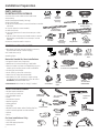
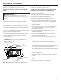
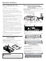
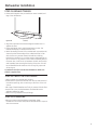
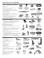
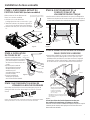
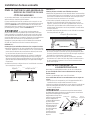
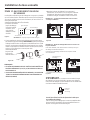
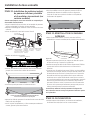
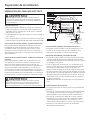
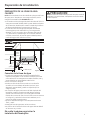
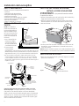
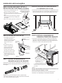
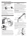
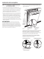
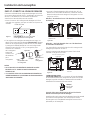
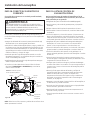
GE Appliances Installation Instructions Built-In Dishwasher If you have questions, call 800.GE.CARES (800.432.2737) or visit our Website at: GEAppliances.com. In Canada, please call 1.800.561.3344 or visit www.geappliances.ca BEFORE YOU BEGIN Read these instructions completely and carefully. WARNING: • 7RUHGXFHWKHULVNRIHOHFWULFVKRFN¿UHRULQMXU\WR persons, the installer must ensure that the dishwasher is completely enclosed at the time of installation. • FOR PERSONAL SAFETY: Remove house fuse or open circuit breaker before beginning installation. Do not use an extension cord or adapter plug with this appliance. • The improper connection of the equipment grounding conductor can result in a risk of electric shock. Check with DTXDOL¿HGHOHFWULFLDQRUVHUYLFHUHSUHVHQWDWLYHLI\RXDUH in doubt that the appliance is properly grounded. • If house wiring is not 2-wire with ground, a ground must be provided by the installer. When house wiring is aluminum, be sure to use UL-Listed anti-oxidant compound and aluminum-to-copper connectors. • :KHQUHLQVWDOOLQJWKHÀRRUSURWHFWSDQPDNHFHUWDLQWKDW the screws have been fully secured. This will ensure that LIWKHXQLWLVSURSHUO\JURXQGHGWKDWWKHÀRRUSURWHFWSDQ will also be grounded. CAUTION: Do not remove wood base until you are ready to install the dishwasher. The dishwasher will tip over when the door is opened if base is removed. FOR YOUR SAFETY Read and observe all WARNINGS and CAUTIONS shown throughout these instructions. While performing installations described in this booklet, gloves, safety glasses or goggles should be worn. IMPORTANT – Observe all governing codes and ordinances. • Note to Installer – Be sure to leave these instructions for the consumer’s and local inspector’s use. • Note to Consumer – Keep these instructions with your Owner’s Manual for future reference. • Skill Level – Installation of this dishwasher requires basic mechanical, electrical and plumbing skills. Proper installation is the responsibility of the installer. Product failure due to improper installation is not covered under the GE Appliance Warranty. See warranty information. • Completion Time – 1 to 3 Hours. New installations require more time than replacement installations. IMPORTANT – The dishwasher MUST be installed to allow for future removal from the enclosure if service is required. Care should be exercised when the appliance is installed or removed, to reduce the likelihood of damage to the power supply cord. If you received a damaged dishwasher, you should immediately contact your dealer or builder. Optional Accessories – See the Owner’s Manual for available custom panel kits. CHECK THE FOLLOWING • Tub trim does not interfere with the door • Dishwasher is square and level at both the top and bottom of the cabinet opening, with no twisting or distortion of the tub or door $OOOHJVRIWKHGLVKZDVKHUDUH¿UPO\LQFRQWDFWZLWKWKH ÀRRU • Drain hose is not pinched between the dishwasher and DGMDFHQWFDELQHWVRUZDOOV 7XEWULPLVIXOO\VHDWHGRQWKHWXEÀDQJH Printed in the United States READ CAREFULLY KEEP THESE INSTRUCTIONS 31-31546 09-14 GE Installation Preparation PARTS SUPPLIED IN INSTALLATION PACKAGE: #10 Hose Clamp • Junction box cover and #10 hex-head screw Drain Hose Junction Hex-Head • Hose clamp Box Cover Junction Box Screw • Drain hose (approximately 78" long) 1/2" long • Drain hose hanger Drain Hose Hanger #8 Hex-Head Mounting • 2 #8-18 hex head screws to secure brackets to washer Bracket Screws tub frame • 1 top trim piece (on some models) Top Trim Piece (on some models) • 2 side trim pieces • 2 mounting brackets for wood countertops or side Side Trim Pieces cabinets • 2 #8-18 x 5/8" Phillips special head screws, to secure dishwasher to underside of countertop or to side #8 Phillips Mounting cabinets Special Brackets Plug Buttons Head Screws • Literature, samples and/or coupons Literature 5/8" long MATERIALS YOU WILL NEED: • 90° elbow (3/4"hose internal thread on one end, opposite end sized to fit water supply) • UL-listed wire nuts (3) • Masking Tape Masking Tape (if applicable) Wire Nuts (3) 90°Elbow Coupler for optional drain hose Materials Needed for New Installations: • Air gap for drain hose, if required • Waste tee for house plumbing, if applicable • Electrical cable or power cord depending on your model, quick connect power cords are availble. • Screw-type hose clamps • Strain relief for electrical connection • Hand shut-off valve (recommended) • Hot Water Line–3/8" minimum, copper tubing (including ferrule, compression nut) or GE Part # WX28X326, flexible braided hose. • WD24X10065 drain hose (12' long), if needed Waste Tee Electrical Cable (or Power Cord, if applicable) Air Gap Strain Relief Hand 6KXW2ȹ Valve TOOLS YOU WILL NEED: • • • • • • • • • • • • • Tubing cutter • Drill and appropriate bits • Hole saw set 2 Hot Water Line Optional 12' Drain Hose WD24X10065 Level Phillips-head screwdriver 1/4" and 5/16" nutdriver Phillips-Head $GMXVWDEOHZUHQFK Screwdriver Level Carpenter's square Measuring tape Safety glasses Flashlight 15/16" Socket %XFNHWWRFDWFKZDWHUZKHQÀXVKLQJWKHOLQH 15/16" socket (optional for skid removal) Gloves Pliers For New Installations Only: Hose Clamps 1/4" and 5/16" Nutdriver Pliers 6" Adjustable Wrench Flashlight Gloves Bucket Carpenter's Square Tubing Cutter Measuring Tape Safety Glasses Hole Saw Set Drill and Bits Installation Preparation PREPARE DISHWASHER ENCLOSURE WARNING: 7RUHGXFHWKHULVNRIHOHFWULFVKRFN¿UHRULQMXU\WRSHUVRQVWKH installer must ensure that the dishwasher is completely enclosed at the time of installation. + 1/4" 33-1/2” to 34-3/4” 34-1/2" Underside Underside ofof Countertop Countertop to Floor to Floor This Wall Area must be Free of Pipes or wires • The dishwasher must be installed so that drain hose is no more than 12' in length for proper drainage. • The dishwasher must be fully enclosed on the top, sides and back, and must not support any part of the enclosure. 24" Min. 4" Plumbing and Electric Service Must Enter Inside This Area 6" Cabinets Square and Plumb 24" Min. CLEARANCES: • When installed into a corner, allow 2" min. clearance between dishwasher and DGMDFHQWFDELQHWZDOORURWKHU appliances. Allow 28-3/8" min. clearance from the front of the dishwasher for door opening. Figure B. Countertop Dishwasher 25-1/2" Figure A Clearance for Door Opening 2" Minimum • The rough cabinet opening must be at least 24" deep, 24" wide and approximately 34-1/2" high from floor to underside of the countertop. Figure B DRAIN REQUIREMENTS • Follow local codes and ordinances. • Do not exceed 15' distance to drain. NOTE: Air gap must be used, if waste tee or disposer connection is less than 18" above floor to prevent siphoning. DETERMINE DRAIN METHOD The type of drain installation depends on the following questions. • Do local codes or ordinances require an air gap? • Is waste tee less than 18" above floor? If the answer to either question is YES, Method 1 MUST be used. • If the answers are NO, either method may be used. Figure C Method 1 – Air Gap with Waste Tee or Disposer An air gap must be used when required by local codes and ordinances. The air gap must be installed according to manufacturer’s instructions. Drain Hose Hanger Drain Hose Hanger CABINET PREPARATION • Drill a 1-1/2" diameter hole in the cabinet wall within the shaded areas shown in Figure A for the drain hose connection. The hole should be smooth with no sharp edges. IMPORTANT – When connecting drain line to disposer, check to be sure that drain plug has been removed. DISHWASHER WILL NOT DRAIN IF PLUG IS LEFT IN PLACE. Remove Drain Plug 18" Min. 32" Min. 18" Min. 32" Min. Figure D Method 2 – “High Drain Loop” with Waste Tee or Disposer Tip: Avoid unnecessary service call charges. Always be sure disposer drain plug has been removed before attaching dishwasher drain hose to the disposer. 3 Installation Preparation PREPARE ELECTRICAL WIRING Alternate Receptacle Location in Adjacent Cabinet WARNING: FOR PERSONAL SAFETY: Remove house fuse or open circuit breaker before beginning installation. Do not use an extension cord or adapter plug with this appliance. 18" 18" Electrical Requirements • This appliance must be supplied with 120V, 60 Hz., and connected to an individual properly grounded branch circuit, protected by a 15- or 20-ampere circuit breaker or time-delay fuse. • Wiring must be 2 wire with ground and rated for 75°C (167°F). • If the electrical supply does not meet the above requirements, call a licensed electrician before proceeding. Grounding Instructions–Permanent Connection This appliance must be connected to a grounded metal, permanent wiring system, or an equipment-grounding conductor must be run with the circuit conductors and be connected to the equipment-grounding terminal or lead on the appliance. Grounding Instructions–Power Cord Models This appliance must be grounded. In the event of a malfunction or breakdown, grounding will reduce the risk of electric shock by providing a path of least resistance for electric current. This appliance is equipped with a cord having an equipmentgrounding conductor and a grounding plug. The plug must be plugged into an appropriate outlet that is installed and grounded in accordance with all local codes and ordinances. WARNING: The improper connection of the equipment grounding conductor FDQUHVXOWLQDULVNRIHOHFWULFVKRFN&KHFNZLWKDTXDOL¿HG electrician or service representative if you are in doubt that the appliance is properly grounded. 4 6" Receptacle Location Area 1-1/2" Dia. Hole (Max.) 3" from Cabinet 6" 24" from Wall Figure E Ground Black White For models equipped with power cord: Do not modify the plug provided with the appliance; if it will not fit the outlet, have a proper outlet installed by a qualified technician. Cabinet Preparation & Wire Routing • The wiring may enter the opening from either side, rear or the floor within the shaded area illustrated above in Figure E and defined in Figure A. • Cut a 1-1/2" maximum diameter hole to admit the electrical cable. Edges of hole should be smooth and rounded. Permanent wiring connections may pass through the same hole as the drain hose and hot water line, if convenient. If cabinet wall is metal, the hole edge must be covered with a bushing. NOTE: Power cords with plug must pass through a separate hole. Electrical Connection to Dishwasher Electrical connection is on the right front of dishwasher. • For permanent connections the cable must be routed as shown in Figure E. Cable must extend a minimum of 24" from the rear wall. • For power cord connections, install a 3-prong grounding type receptacle in the sink cabinet rear wall, 6" min. or 18" maximum from the opening, 6" to 18" above the floor. • Use only WX09X70910 or WX09X70911 Dishwasher Power Cord Kit. Installation Preparation PREPARE HOT WATER LINE NOTE: GE recommends copper tubing for the water line, but if \RXFKRRVHWRXVHÀH[LEOHKRVHXVH*(·VWX28X326ÀH[LEOH braided hose. CAUTION: Do not remove wood base until you are ready to install the dishwasher. The dishwasher will tip over when the door is opened if base is removed. • The water supply line (3/8” copper tubing or flexible braided hose) may enter from either side, rear or floor within the shaded area shown in Figure F. • The water supply line may pass through the same hole as the electrical cable and drain hose. Or, cut an additional 1-1/2" diameter hole to accommodate the water line. If power cord with plug is used, water line must not pass through power cord hole. 1-1/2" Dia. Hole Hot 4" Shut-off Valve 2" From Cabinet Cabinet Face 6" 19" From Wall 2" From Floor Figure F Water Line Connection • If using a flexible braided supply hose, label the hose with the installation date to use as reference. Flexible braided hoses, elbows and gaskets should be replaced in 5 years. • Turn off the water supply. • Install a hand shut-off valve in an accessible location, such as under the sink. (Optional, but strongly recommended and may be required by local codes.) • Water connection is on the left side of the dishwasher. Install the hot water inlet line, using no less than 3/8" copper tubing or a flexible braided hose. Route the line as shown in Figure F and extend forward at least 19" from rear wall. $GMXVWZDWHUKHDWHUIRU)WR)WHPSHUDWXUH • Flush water line to clean out debris. • The hot water supply line pressure must be 20-120 PSI. Turn page to begin dishwasher installation. 5 Dishwasher Installation STEP 3: REMOVE WOOD BASE, INSTALL LEVELING LEGS STEP 1: PREPARATION Locate the items in the installation package: • Screws • Junction box cover • Drain hose and clamp • Mounting brackets • Trim pieces (on some models) • Drain hose hanger • Owner's Manual • Product samples and/or coupons IMPORTANT – 'RQRWNLFNRȺZRRGEDVH Damage will occur. • Move the dishwasher close to the installation location and lay it on its back. NOTE: Do not place the dishwasher on its side. • Remove the 4 leveling legs on the underside of the wood base with a 15/16" socket wrench. • Discard base. STEP 2: CHECK DOOR BALANCE NOTE: If installing a Custom Door Panel (available on some models), please follow the instructions found in the Custom Door Panel kit. Door closes within 20° Approx. 1/2" Door stays in position from 20° to 70° • With dishwasher on the wood base, check the door balance by opening and closing the door. Door falls fully open beyond 70° Side View Figure G • Door is properly balanced if, when opened, it self closes within 20° from vertical, stays in position from 20° to 70° and falls fully open beyond 70°. • If necessary increase or decrease tension as shown. Some models will have 1 spring on each side and other models will have 2 springs on one side and 1 spring on the other side. /DWFKGRRUDQGDGMXVWVSULQJVWRFRUUHFWEDODQFH Figure I • Screw leveling legs back into the dishwasher frame, approximately 1/2" from frame as shown. NOTE:6RPHPRGHOVKDYHUHDUDGMXVWDEOHOHYHOLQJZKHHOVDQG will not require the 2 rear leveling legs. STEP 4: REMOVE TOEKICK • Remove the 2 toekick screws and toekick. Set aside for use in Step 23. To ek ic k Side View Custom door panel Figure J Front View Increase Tension Decrease Tension Spring hooked to screw inside leg Make sure pulley cables are within pulley shoulders Figure H Tip: Make sure door opens and closes smoothly. Check door opening and closing. If door does not open easily or falls too quickly, check spring cable routing. The cable is held in place by “shoulders” on the pulley. Check to be sure cable has not slipped over the pulley shoulders and is routed as shown. 6 Remove 2 Toekick Screws Dishwasher Installation STEP 5: IF NECESSARY, REMOVE FLOOR PROTECT (on some models) STEP 8: POSITION WATER LINE AND HOUSE WIRING • Disconnect leak sensor wire (on some models). • Remove 2 screws from front of the Floor Protect with a ¼” driver. • Lower front of pan and slide out from under dishwasher. • Set aside for use in Step 21. • Position water supply line and house wiring on the floor of the opening to avoid interference with base of dishwasher and components under dishwasher. Squeeze connector at top to release snap feature 4" 4" Leak Sensor 6" 6" Water Line House Wiring Floor Protect Figure O Figure L STEP 6: INSTALL 90° ELBOW • Thread 90° elbow onto the water valve. Ensure rubber gasket is located between valve and elbow. • Do not overtighten elbow. Water valve bracket could bend or water valve fitting could break. • Position the end of the elbow to face the rear of the dishwasher. Front of dishwasher STEP 9: INSTALL DRAIN HOSE, THROUGH CABINET • Position dishwasher in front of cabinet opening. Insert drain hose into the hole in cabinet side. If a power cord is used, guide the end through a separate cabinet opening. Water Valve Bracket 90° Elbow Fill Hose Figure M STEP 7: INSTALL DRAIN HOSE TO DRAIN LOOP Connect drain loop end to drain hose using the screw clamp as shown in the figure. Insulation Blanket House Wiring Power Cord (If used) Water Line Drain Hose Ensure drain hose is not twisted or pinched Maximum drain hose length is 15' Do not disconnect or remove high drain loop from left side of dishwasher Figure P 7LS3UHYHQWXQQHFHVVDU\VHUYLFHFDOOFKDUJHVIRU¿OOGUDLQ or noise concerns. Position utility lines so they do not interfere with anything under or behind the dishwasher. Figure N NOTE: The high drain loop on the side of the tub is designed for better wash performance. Do not remove from the side of the tub. 7 Dishwasher Installation STEP 10: SLIDE DISHWASHER THREE-FOURTHS OF THE WAY INTO CABINET IMPORTANT – Do not push against front panel with knees. Damage will occur. • Grasp the sides of the front panel and slide dishwasher into the opening a few inches at a time. STEP 12: INSTALL MOUNTING BRACKETS You will need the mounting brackets and 2 #8 hex-head screws set aside in Step 1. You must install the mounting brackets onto the dishwasher tub frame top or sides prior to sliding the dishwasher into place under the countertop. This dishwasher is capable of a true-flush installation at a 24” deep opening. The mounting brackets have several available attachment positions to accommodate different cabinet constructions. Install mounting brackets on top if the underside of countertop is wood or wood-like material that accepts screws: Do not push against front door panel with knee. Damage to the door panel will occur. Figure Q • As you proceed, pull the drain hose through the opening under the sink. Stop pushing when the dishwasher extends about 6 inches IRUZDUGRIDGMDFHQWFDELQHWV • Make sure drain hose is not kinked under or behind the dishwasher. • Make certain the house wiring, drain line and water line do not interfere with components under dishwasher. IMPORTANT - After installing brackets and before FORVLQJWKHGLVKZDVKHUGRRUDGMXVWWKHEUDFNHWVE\EHQGLQJ them up as needed, so that they do not contact the top of the dishwasher door and cause damage. Top Mounting STEP 11: INSTALL TRIM PIECES In this step you will need the trim pieces set aside in Step 1. Top Trim #8 Bracket Screw Bracket Dishwasher tub frame Side Trim Bend and break here after installing if counter has a short overhang. Figure S Top View Side Trim Side Trim • If you are installing the dishwasher under a counter with a short overhang, the countertop brackets may extend beyond the edge of the counter. If this is the case, remove the excess length by repeatedly bending the brackets at the front notch only until they break. Install mounting brackets on sides if the countertop is Figure R granite or similar material that will not accept wood screws: )XOO\VHDWWRWXEÀDQJH Tub frame %UHDNRȺIURQWSRUWLRQRIWKHWDEZLWKSOLHUVDWWKHORFDWLRQVKRZQ prior to attaching to dishwasher. • Position the left-hand side bracket as shown. Repeat with the right bracket. Tub trim Top View Door Side Mounting Dishwasher tub frame Handle Do not screw into cabinet face frame • Select the top trim piece (See Figure R) and line up center to the top ODWFK3UHVVWKHWULPSLHFHRQWRWKHWXEÀDQJHPRYLQJIURPRQHVLGH to the other. #8 Bracket screw as supplied • Select the left trim piece (see Figure R).Align top edge with the top WULPDQGSUHVVLWRQWRWKHOHIWVLGHRIWKHWXEÀDQJHPRYLQJIURPWKH WRSWRWKHERWWRP5HSHDWIRUWKHULJKWVLGHWXEÀDQJHWULPSLHFH (See Figure R for right side trim piece.) Do not pinch the latch wires in #8 bracket screw 8 Tub trim Figure T Bend and break here if necessary Bracket Dishwasher Installation STEP 13: PUSH DISHWASHER INTO FINAL POSITION • Open and close the dishwasher door to be sure it operates VPRRWKO\DQGGRHVQRWUXERQWKHDGMDFHQWFDELQHW • Check the tub insulation blanket, if equipped, to be sure it is smoothly wrapped around the tub. It should not be “bunched up” and it must not interfere with the door springs. If the insulation is “bunched up” or interfering with the springs, straighten and recenter the blanket prior to sliding the dishwasher into its final position. • Slide the dishwasher into the final position by pushing on the sides of the door panel. Do not push or pull the door in a partially open or closed position when moving the dishwasher. Do not use a knee or push on the center of the panel. If you do, damage to the panel will likely result. Check that the dishwasher is squarely positioned in the cabinet opening at both the top and the bottom of the appliance prior to mounting to the cabinet. IMPORTANT – Before opening the dishwasher door, be certain the edges of the dishwasher door panel are behind WKHIDFHRIWKHDGMDFHQWFDELQHWDQGQRWXSDJDLQVWWKHFDELQHW face. Refer to Figure U. If the dishwasher door is opened when the edge of the door is against the face of the cabinet, dishwasher door damage and cabinet damage will occur. Door Fits and Swings Back Behind Cabinet Frame Correct Alignment Figure U Incorrect Alignment will result in door damage Door Catches on Cabinet Frame Tip: Prevent unnecessary service charges for panel damage or wash performance. Check dishwasher alignment prior to opening dishwasher door to prevent panel damage. Make sure utility lines are not trapped or crushed behind dishwasher. Crushed lines will restrict water flow. Do not allow tub trim to get trapped by or come into contact with the door Check that tub trim does not contact the door at all points Tub frame Tub trim Top View Door Top View Tub trim trapped E\GRRU Handle Tub trim may be trimmed if necessary to ensure proper door operation 9 Dishwasher Installation STEP 14: LEVEL DISHWASHER IMPORTANT – Dishwasher must be level for proper dish rack operation, wash performance and door operation. The dishwasher must be leveled left to right and front to back. This ensures the dish racks will not roll in or out on their own, FLUFXODWLRQZDWHUZLOOÀRZWRWKHSXPSLQOHWDQGWKHGRRUZLOOFORVH without hitting the side of the tub. • Remove the lower dish rack and place a level on the door and lower rack track as shown in Figure V. • If your model has 4 leveling feet, DGMXVWWKHOHYHORIWKH dishwasher by individually turning the 4 legs on the bottom of the dishwasher as illustrated in Figure W. • If your model has rear wheels, the height of the ZKHHOVDUHDGMXVWHGIURP the front of the dishwasher Figure V along with the 2 front legs $GMXVW on the bottom of the dishwasher. Begin the leveling process with the front legs by individually turning the front 2 legs. By DGMXVWLQJWKHIURQW legs first, access to the rear leveling bolts is maximized easing rear wheel DGMXVWPHQW When the front legs DUHDGMXVWHG to a height resulting in an Figure W appropriate gap to the upper FDELQHWSURFHHGWRDGMXVWWKHUHDUOHYHOLQJZKHHOVE\DGMXVWLQJWKH OHYHOLQJEROWV,QGLYLGXDOO\WXUQWKHEROWVWRDGMXVWWKHUHDUZKHHOV Slowly rotate the 2 bolts counter clockwise to raise the back of the dishwasher, and clockwise to lowerLW&RQWLQXHWRDGMXVWWKHIHHW and wheels until the dishwasher is level as illustrated in Figure W. Ensure all 4 legs/wheels are firmly in contact with the floor. • The dishwasher is properly leveled when the level indicator is centered left to right and front to back. Also, the dishwasher door should close without hitting the side of the tub. • Replace the lower rack. • Pull each rack out, about halfway. Check to be sure it does not UROOEDFNRUIRUZDUGRQWKHGRRU,IWKHUDFNPRYHVDGMXVW leveling legs. 10 Tip: Prevent unnecessary service charges. Verify dishwasher is leveled. Pull the dish racks half way out. They should stay put. Open and FORVHWKHGRRU7KHGRRUVKRXOG¿WLQWKHWXERSHQLQJZLWKRXW hitting the side of the tub. If the racks roll on their own, or the door hits the side of tub, relevel the dishwasher. Dishwasher Installation STEP 15: POSITION DISHWASHER, SECURE TO COUNTERTOP OR CABINET In this step you will need the 2 Phillips special head screws from the screws set aside in Step 1. The dishwasher must be secured to the countertop or the cabinet sides. When the underside of the countertop is wood, use Method 1. Use Method 2 when the underside of the countertop is made of a material, such as granite, that will not accept wood screws. IMPORTANT – Prevent door panel and control Method 2 Secure dishwasher to cabinet sides. • Recheck alignment of the dishwasher in the cabinet. Refer to Steps 13 and 14. Door panel and/or control panel must not hit cabinets or countertop. )DVWHQWKHGLVKZDVKHUWRWKHDGMDFHQWFDELQHWVZLWKWKH 2 Phillips special head screws provided. Refer to Figure X. 0DNHFHUWDLQVFUHZVDUHGULYHQVWUDLJKWDQGÀXVKWRSUHYHQW panel damage. Do not screw into the cabinet face frame. • Install plug buttons to the side of the tub well in the holes provided. Solid Surface Countertop Granite Countertop panel damage. Dishwasher must be positioned so the front SDQHODQGFRQWUROSDQHOGRQRWFRQWDFWWKHDGMDFHQWFDELQHWV or countertop. Mounting screws must be driven straight and flush. Protruding screw heads could scratch the door panel or control panel and interfere with door operation. Method 1 Secure dishwasher to underside of wood countertop. • Recheck alignment of the dishwasher in the cabinet. Refer to Steps 13 and 14. Door panel and/or control panel must not hit cabinets or countertop. • Fasten the dishwasher to the underside of the countertop ZLWKWKH3KLOOLSVVSHFLDOKHDGVFUHZV5HIHUWR¿JXUH 0DNHFHUWDLQVFUHZVDUHGULYHQVWUDLJKWDQGÀXVKWRSUHYHQW panel damage. • Install plug buttons to the side of the tub well in the holes provided. Brackets Wood Countertop Side Brackets Figure X • Re-check that the dishwasher is squarely positioned in the cabinet at both the top and bottom of the appliance after PRXQWLQJWRWKHFDELQHWVFRXQWHUWRS$GMXVWLIQHFHVVDU\ • Confirm all leveling legs are in contact with the floor to prevent the dishwasher from rocking and ensure proper door and latch operation STEP 16: CONNECT WATER SUPPLY Connect water supply line to 90° elbow. If using a flexible braided hose connection: $WWDFKQXWWRHOERZXVLQJDQDGMXVWDEOHZUHQFK If using a copper tubing connection: • Slide compression nut, then ferrule over end of water line. • Insert water line into 90° elbow. • Slide ferrule against elbow and secure with compression nut. IMPORTANT – Check to be sure that door spring DQGRUGRRUVSULQJFDEOHGRQRWUXERUFRQWDFWWKH¿OOKRVHRU water supply line. Hot Water Supply Line Test by opening and Compression 90° Elbow closing the door. Nut Reroute the water supply lines if a rubbing noise or interference Ferrule occurs. Figure Y Bottom Left Side 11 Dishwasher Installation STEP 17: CONNECT DRAIN LINE The molded end of the drain hose will fit 5/8" through 1" diameter inlet ports on the air gap, waste tee or disposer. • Determine size of inlet port. • Cut drain hose connector on the marked line, if required, WR¿WWKHLQOHWSRUW • Connect drain line to air gap, waste tee or disposer using the previously determined method. Secure hose with a screwtype clamp. Method 1 – Air gap with waste tee or disposer Cutting Line 1" Figure Z 5/8" IMPORTANT: Do not cut corrugated portion of hose • If a longer drain hose is required and you did not purchase drain hose WD24X10065, add up to 66" length for a total of 144" (12 feet) to the factory-installed hose. Use 5/8" or 7/8" inside diameter hose and a coupler to connect the 2 hose ends. Secure the connection with hose clamps. 7^bT2[P\_ 2^d_[Ta Figure AA Waste Tee Installation Disposer Installation Figure AB Method 2 – “High drain loop” with waste tee or disposer With this method you will need the drain hose hanger set aside in Step 1. Fasten drain hose to underside of countertop with the provided hanger. Drain Hose Hanger 7^bT2[P\_ NOTES: • DRAIN CONNECTION HEIGHT IS NOT TO EXCEED 72" ABOVE BOTTOM OF DISHWASHER. • TOTAL DRAIN HOSE LENGTH MUST NOT EXCEED 12 FEET FOR PROPER DRAIN OPERATION. 18" Min. Waste Tee Installation Figure AC 32" 18" Min. Min. 32" Min. Disposer Installation IMPORTANT – When connecting drain line to disposer, check to be sure that drain plug has been removed. DISHWASHER WILL NOT DRAIN IF PLUG IS LEFT IN PLACE. Remove Drain Plug Tip: Avoid unnecessary service call charges for a no drain complaint. Make sure excess drain hose has been pulled through the cabinet opening. This will prevent excess hose in the dishwasher cavity from becoming kinked or crushed by the dishwasher. 12 Dishwasher Installation STEP 18: CONNECT POWER SUPPLY STEP 19: PRETEST CHECKLIST If a power cord with plug is already installed proceed to Step 19. Review this list after installing your dishwasher to avoid charges for a service call that is not covered by your warranty. • Check to be sure power is OFF. WARNING: If house wiring is not 2-wire with ground, a ground must be provided by the installer. When house wiring is aluminum, be sure to use UL-Listed anti-oxidant compound and aluminum-to-copper connectors. ,QWKLVVWHS\RXZLOOQHHGWKHMXQFWLRQER[FRYHUDQGWKH #10 Hex head screw from the screws set aside in Step 1. 6HFXUHKRXVHZLULQJWRWKHEDFNRIWKHMXQFWLRQER[ZLWKD strain relief. • Locate the 3 dishwasher wires, (white, black and green) with WKHVWULSSHGHQGVFRPLQJRXWRIWKH$&MXPSHU8VH8/OLVWHG wire nuts of appropriate size to connect incoming ground to green, white to white and black to black. ,QVWDOOWKHMXQFWLRQER[FRYHUXVLQJKH[KHDGVFUHZ Check to be sure that wires are not pinched under the cover. 0DNHVXUHWKDWWKHMXQFWLRQER[FRYHULVUHVWLQJRQWKH mounting bracket. • If using a Power Cord Kit, use GE part number WX09X70910 or WX09X70911 and refer to the included instructions. NOTE: Do not remove the Junction Box Bracket. White Ground (Green) AC Jumper • Open door and remove all foam and paper packaging. • Locate the Owner’s Manual set aside in Step 1. • Read the Owner’s Manual for operating instructions. • Check door opening and closing. If door does not open and close freely, check for proper routing of spring cable over SXOOH\,IGRRUGURSVRUFORVHVZKHQUHOHDVHGDGMXVWVSULQJ tension. See Step 2. • Check to be sure that wiring is secure under the dishwasher, not pinched or in contact with door springs or other components. See Step 18. • Check door alignment with tub. If door hits tub, level dishwasher. See Step 14. • Check door alignment with cabinet. If door hits cabinet, reposition dishwasher. See Step 13. • Check that door spring does not contact water line, fill hose, wiring or other components. See Step 13. • Verify water supply and drain lines are not kinked or in contact with other components. Contact with motor or dishwasher frame could cause noise. • Turn on the sink hot water faucet and verify water temperature. Incoming water temperature must be between 120°F and 140°F. A minimum of 120°F temperature is required for best wash performance. See “Prepare Hot Water Line,” page 5. • Add 1 quart of water to the bottom of the dishwasher to lubricate the pump seal. • Turn on water supply. Check for leaks. Tighten connections if needed. Black Figure AD Junction Box Bracket Ground Screws • Remove protective film if present from the control panel and door. • Check that tub trim does not contact the door. NOTE: All ground screws, brackets and wires must remain intact. 13 Dishwasher Installation STEP 20: DISHWASHER WET TEST • Turn on power supply or plug power cord into outlet, if equipped. • Select a cycle to run and push the Start button. • Ensure the door is latched. Dishwasher should start. • Check to be sure that water enters the dishwasher. If water does not enter the dishwasher, check to be sure that water and power are turned on. STEP 22: POSITION INSULATION, PRETOEKICK, AND SOUND BARRIER (on some models) Skip this step if the sound insulation package is not supplied with the dishwasher. • Locate the sound insulation package and pre-toekick