1
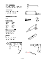
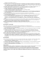
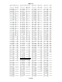
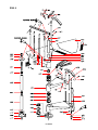
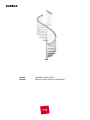
EUREKA
English
Español
ASSEMBLY INSTRUCTION
INSTRUCCIONES PARA EL ENSAMBLAJE
EUREKA
English
Before starting to assemble unpack each element of the staircase. Position them on an ample surface and check
the quantity of the elements (TAB. 1); (A = Code, B = Quantity).
We recommend watching the DVD provided before starting the assembly.
Preliminary assembly
1.
2.
3.
Assemble the connector D32 on the treads L02 with ring nut D33 and tighten manually. Insert components C13 and C31 in the bushes D32 (fig. 2) orienting the dowel hole towards the centre of the staircase.
Carefully measure the height from floor to floor to determine the number of spacer rings D03
(TAB. 2 - cm) (TAB. 2 - in.).
Assemble the spacers D14, D03 and D02 (fig. 1) as a single piece. Assemble the spacers D04, D03 and D02
in the same way (fig. 1).
Assembly
4. To determine the fixing point of base G03 on the floor calculate the exact centre of the final landing (fig. 3).
5. Drop a plumb line to the floor in correspondence with the point just found, trace a line perpendicular to the wall to identify the exact centre of the staircase using one of the cardboard packs in the box.
6. Calculate the centre of the staircase according to its own size.
E.g. D. 140 cm - 4'7 ⅛” = (140 : 2) + 2,5 cm - 63/64"= 72,5 cm - 2'4 ½”
7. Use element G03 as a reference for the 3 floor fixing holes to perform using a D. 14 mm - 35/64" bit.
8. Assemble the base (G03+B17+B46) as in fig. 1.
9. Secure the base (G03+B17+B46) in a permanent manner to the floor with the elements B13 (fig. 1).
10.Tighten the tube G02 onto the base (G03+B17+B46) (fig. 1).
11.Insert the spacers (D14+D03+D02) (fig. 4).
12.Insert the base cover D05 (fig. 4).
13.Insert the first tread L02 into tube G02. Then, in this order, insert a spacer (D04+D03+D02) and the next tread L02 and so on. Position the treads, alternating between right and left, so that the weight is evenly distributed (fig. 4).
14.Once you have reached the end of the tube G02, tighten element B47, tighten the following tube G02 and continue to assemble the staircase (fig. 4).
15.Once you have reached the end of the tube G02, tighten element B46 and element G01 (tighten element G01 taking into account the fact that it must be 15 cm - 5' ⅞" taller than the height of the staircase) (fig. 5). Continue to insert the treads using element D01 inserted in the spacer (D04+D03+D02) of the final treads L02 that are not centred on column G02.
16.Insert the landing E03 last. Insert elements B05, B04 and secure element B03 sufficiently, considering that the treads must still rotate (fig. 1).
Fixing the landing
17.Screw element B74 onto the landing E03 using the components BA2, BA6 and BA9 in the sequence shown in fig. 6.
18.Connect both elements B76 and B74 by means of components BB1 and BB2 without permanently tightening them (fig. 6). Upper BB1 must be screwed into B74 up to 15 mm - 19/32" from the edge.
19.Move elements B76 close to the floor. Determine the position and tighten elements BB1 (after checking that the staircase is vertical) until points A, B and C are in contact with the floor (fig. 7).
20.Drill with a D. 14 mm - 35/64" bit and fix in a permanent manner using element B13 (fig. 6).
21.Lock element BA2 last (fig. 6).
To assemble the railing
22.Fan the treads L02 out after you have chosen the rotation direction (fig. 9). You can now climb the stairs.
23.Starting from the landing E03 insert the first long baluster C03 (H.1230 mm - 4' ⅜") connecting the treads L02 keeping the direction of holes of element B53 towards the centre of the staircase and in such a way that the countersink of the element remains towards the inside of the railing.
24.Then insert all the longer connecting balusters C03 (H.1230 mm - 4' ⅜") between the treads L02. Only tighten the lower element C31 of each tread (fig. 1).
25.Check that all the balusters C03 positioned are vertical. Take care during this operation, since it is very important for assembling the stairs correctly.
26.Tighten in a permanent manner the element B03 (Fig. 9).
27.Tighten in a permanent manner the upper element C31 of the treads (fig. 2).
28.Check that the balusters C03 are vertical and correct this, if necessary, repeating the operations described in points 25, 26 and 27.
29.Identify the fixing point of element F01 on the floor in correspondence with the first baluster C03 (H. 1230 mm EUREKA
- 4'⅜"). After checking that it is vertical, take off the column and drill with a D. 8 mm - 5/16” bit. Use the elements B11, B12 and C31 (Fig. 1). If installing outdoors seal the point where element F01 rests on the ground with silicone (not included).
30.Position the first baluster C03 (H. 1230 mm - 4' ⅜") together with the element F07 after cutting it by 35 mm - ⅜". Finally secure element F07 to baluster C03 by means of the components C31.
31.Heat the handrail A02 until it is malleable (fig. 10):
1) rest the handrail on the cover of the wooden box,
2) slowly heat it performing circular movements without stopping,
3) overturn the handrail and repeat the operation.
32.Position the handrail A02 on the balusters C03 (using gloves). Fix it on the first column C03 at the top with elements B54 and B55 after drilling it with a D. 5 mm - 13/64" bit in its lower part before it cools (fig. 9).
33.Cut the exceeding part of handrail A02 so that it does not hamper the operations.
34.Drill handrail A02 in correspondence with the holes present on all the elements B53 and fix it with elements B54 and B55 (fig. 1).
35.Insert the remaining balusters C03 in the treads L02 in close succession (for a D. 120 cm - 3' 11 ¼” staircase only one intermediate column H.1135 mm - 3'8 ⅝”; for D. 140 cm - 4'7 ⅛" and D. 160 cm - 5'3" staircases two intermediate columns H. 1100 mm - 3'7 ¼" and H. 1170 mm - 3'10"). Tighten elements C31 taking care that they are vertical and fix them to the handrail A02 using elements B54 and B55.
36.In correspondence with the first baluster C03 of the staircase, perform a final cut of the handrail A02.
37.Insert element A03 on handrail A02 (eliminate burrs due to cut) using the glue X01 after heating the end of handrail A02 (fig. 1).
38.Secure elements C31, D32 and D33 in a permanent manner using the part C36.
39.Complete the railing assembly by inserting elements B82 into the lower part of the balusters C03 (fig.1).
Assembling the balustrade
40.Screw column C04 onto element G01 protruding from the landing E03 (fig. 1).
41.Fasten element B01 onto column C04 using element C31 and seal it with silicone if installing outdoors (Fig. 1).
42.Fix elements F01 using the components B89, B27, B23 in the holes present on the landing E03 as in fig. 1.
43.Position the shorter balusters C03 H.975mm - 3’2 ⅜” in the elements F01 (applying silicone, not included, to seal the space between the two elements if installing outdoors) and tighten element C31 (fig. 1). In the hole with the elements D32 and D33 on the landing E03 use a baluster C03 H.1100 mm - 3’7 ¼” cutting it by
95 mm - 47/64”.
44.Secure the handrail A18 using elements B54 and B55 (fig. 1).
45.Connect the end part of the railing to the short stretch of the balustrade on landing E03 using the appropriate fixture obtained when assembling elements A20, A03, C92 and B08 (fig. 11). On the handrail A02 clean the cut and heat the end part, fix the caps A03 of the fixture obtained (after cleaning the cut and heating the end part of the handrail A02) using the glue X01, fix in a permanent manner with screws C87 (fig. 11).
Final Assembly
46.To further stiffen the staircase at intermediate points, secure elements F09 to the wall and join them to the balusters C03 using elements F08. Drill using a D. 8 mm - 5/16” bit and use elements B36, B37, C29, B11 and B12 (fig. 13).
47.Glue the nosings H06 onto the treads L02 using element B96 (Fig. 1). If installing outdoors use silicone.
48.Glue the step board H03 and H04 onto the landing E03 using element B96 (fig. 1) for use indoors, and silicone (not included) for use outdoors.
Maintenance
After assembly check the integrity of the staircase and touch up any damaged parts with a rust-proofing undercoat
(not provided) and a topcoat of varnish included in the supply.
To ensure a long life of the product, it is recommended to periodically perform the above operation.
In case of accidental damage to the varnishing, and in any case at least every 4 months, carry out the above
described operation.
Stairs installed in particularly aggressive environments (for example, near the sea, in industrial areas, etc.) must be
washed every month with fresh water and non-aggressive detergents, without using pressurized water.
EUREKA
Español
Antes de comenzar el ensamblaje, desembale todos los elementos de la escalera. Colóquelos sobre una superficie
amplia y verifique la cantidad de los elementos (TAB. 1); (A = Código, B = Cantidad).
El suministro incluye un DVD que debe verse antes de comenzar el montaje.
Ensamblaje preliminar
1.
2.
3.
Ensamble los casquillos D32 en los peldaños L02 con la abrazadera D33 y apriete manualmente. Introduzca los componentes C13 y C31 en los casquillos D32 (fig. 2), orientando la abertura del tornillo sin cabeza hacia el centro de la escalera.
Mida cuidadosamente la altura de pavimento a pavimento para determinar la cantidad de riostras D03
(TAB. 2 - cm) (TAB. 2 - in.).
Ensamble los distanciadores (D14, D03 y D02) como una pieza única (fig. 1). Ensamble del mismo modo los distanciadores D04, D03 y D02 (fig. 1).
Ensamblaje
4. Para determinar el punto de fijación de la base G03 en el pavimento, calcule el centro exacto de la salida final (fig. 3).
5. Baje hasta el suelo un alambre vertical, de modo que coincida con el punto recién hallado, y trace una línea perpendicular a la pared para identificar el centro exacto de la escalera, utilizando uno de los cartones presentes en la caja.
6. Calcule el centro de la escalera en función de su medida.
Ej. Ø 140 cm - 4’7 ⅛” = (140 : 2) + 2,5 cm - 63/64” = 72,5 cm - 2’4 ½”
7. Utilice el elemento G03 como referencia para las 3 aberturas de fijación al suelo, que deben realizarse con una broca Ø 14 mm - 35/64”.
8. Ensamble la base (G03+B17+B46) como se indica en la fig. 1.
9. Fije definitivamente la base (G03+B17+B46) al pavimento con los elementos B13 (fig. 1).
10.Enrosque el tubo G02 en la base (G03+B17+B46) (fig. 1).
11.Introduzca los distanciadores (D14+D03+D02) (fig. 4).
12.Introduzca el cubrebase D05 (fig. 4).
13.Introduzca el primer peldaño L02 en el tubo G02. Luego, en el orden correspondiente, introduzca un distanciador (D04+D03+D02) y el próximo peldaño L02 y así, sucesivamente. Coloque los peldaños alternándolos a la derecha y a la izquierda, de modo que el peso quede distribuido uniformemente (fig. 4).
14.Al alcanzar el extremo del tubo G02, enrosque el elemento B47, enrosque el próximo tubo G02 y siga ensamblando la escalera (fig. 4).
15.Al alcanzar el extremo del tubo G02, enrosque el elemento B46 y el elemento G01 (enrosque el elemento G01 considerando que debe superar la altura de la escalera por unos 15 cm - 5' ⅞". (fig. 5). Siga introduciendo los peldaños utilizando el elemento D01 introducido en el distanciador (D04+D03+D02) de los peldaños finales L02 no centrados en el palo G02.
16.Por último, introduzca la meseta E03. Introduzca los elementos B05 y B04 y apriete el elemento B03 lo suficiente, considerando que los peldaños aún deben girar (fig. 1).
Fijación de la meseta
17.Enrosque a la meseta E03 el elemento B74 utilizando los componentes BA2, BA6 y BA9 en la secuencia que se indica en la fig. 6.
18.Conecte ambos elementos B76 al B74 por medio de los componentes BB1 y BB2 sin apretar definitivamente (fig. 6). El BB1 superior debe enroscarse en el B74 hasta quedar a 15 mm - 19/32" del tope.
19.Acerque los elementos B76 al forjado. Determine la posición y apriete los elementos BB1 (tras haber comprobado la verticalidad de la escalera) hasta llegar los puntos A, B y C en contacto con el pavimento (fig. 7)
20.Perfore con la broca Ø 14 mm - 35/64" y fije definitivamente utilizando el elemento B13 (fig. 6).
21.Por último, bloquee el elemento BA2 (fig. 6).
Ensamblaje de la barandilla
22.Ensanche en forma de abanico los peldaños L02 tras haber elegido el sentido de rotación (fig. 9). Ahora es posible subirse a la escalera.
23.Comenzando desde la meseta E03, introduzca el primer barrote largo C03 (H. 1230 mm - 4' ⅜") de conexión entre los peldaños L02, manteniendo la orientación de las aberturas del elemento B53 hacia el centro de la escalera y de modo que el avellanado del elemento permanezca hacia el interior de la barandilla.
24.Luego, introduzca todos los barrotes más largos C03 (H. 1230 mm - 4' ⅜") de conexión entre los peldaños L02. Apriete solamente el elemento inferior C31 de cada peldaño (fig. 1).
25.Compruebe la verticalidad de todos los barrotes C03 colocados. Preste atención a esta operación porque es muy importante para obtener un ensamblaje correcto.
26.Apriete definitivamente el elemento B03 (fig. 9).
27.Apriete definitivamente el elemento superior C31 de los peldaños (fig. 2).
28.Vuelva a controlar la verticalidad de los barrotes C03 y, si hace falta, corríjala repitiendo las operaciones EUREKA
descritas en los puntos 25, 26 y 27.
29.Identifique el punto de fijación del elemento F01 en el pavimento, de modo que coincida con el primer barrote C03 H. 1230 mm - 4’ ⅜”. Tras haber controlado su verticalidad, quite el barrote y perfórelo con la broca Ø 8 mm - 5/16”. Utilice los elementos B11, B12 y C31 (fig. 1). En caso de puesta en servicio en exterior, selle con silicona (no suministrada) el punto de apoyo del elemento F01 a tierra.
30.Coloque el primer barrote C03 (H. 1230 mm - 4' ⅜") junto al elemento F07 tras haberle cortado 35 mm - ⅜". Apriete definitivamente el elemento F07 en el barrote C03 por medio de los componentes C31.
31.Caliente el pasamanos A02 hasta que quede maleable (fig. 10):
1) apoye el pasamanos en la tapa de la caja de madera,
2) caliente lentamente realizando movimientos circulares sin detenerse nunca,
3) déle la vuelta al pasamanos y repita la operación.
32.Coloque el pasamanos A02 en los barrotes C03 (utilice guantes). Fíjelo en el primer barrote C03 superior con los elementos B54 y B55, tras haberlo perforado con una broca Ø 5 mm - 13/64" en su parte inferior antes de que se enfríe (fig. 9).
33.Corte gran parte del pasamanos A02 excesivo para evitar que obstaculice las operaciones.
34.Perfore el pasamanos A02 donde coincida con las aberturas presentes en todos los elementos B53 y fije con los elementos B54 y B55 (fig. 1).
35.Luego, introduzca rápidamente los demás barrotes C03 en los peldaños L02 (para la escalera Ø 120 cm 3' 11 ¼”, un solo barrote intermedio H.1135 mm - 3'8 ⅝”; para las escaleras Ø 140 cm - 4'7⅛" y
Ø 160 cm - 5'3", dos barrotes intermedios H. 1100 mm - 3'7¼" y H. 1170 mm - 3'10"). Apriete los elementos C31 prestando atención a su verticalidad y fije el pasamanos A02 utilizando los elementos B54 y B55.
36.En el punto que coincide con el primer barrote C03 de la escalera, realice el corte definitivo del pasamanos A02.
37.Introduzca el elemento A03 en el pasamanos A02 (elimine las rebabas causadas por el corte) utilizando el pegamento X01 tras haber calentado el extremo del pasamanos A02 (fig. 1)
38.Apriete definitivamente los elementos C31, D32 y D33 utilizando el art. C36.
39.Complete el ensamblaje de la barandilla introduciendo los elementos B82 en la parte inferior de los barrotes C03 (fig. 1).
Ensamblaje de la balaustrada
40.Enrosque el barrote C04 en el elemento G01 que sobresale de la meseta E03 (fig. 1).
41.Fije el elemento B01 en el barrote C04, utilizando el elemento C31 y sellando con silicona (no suministrada) en caso de puesta en servicio en exterior (fig. 1).
42.Fije los elementos F01, utilizando los componentes B89, B27 y B23, en las aberturas presentes en la meseta E03, como se indica en la fig. 1.
43.Coloque los barrotes más cortos C03 H.975 mm (3’2 ⅜”) en los elementos F01 (aplicando silicona, no suministrada, para sellar el espacio entre los dos elementos, en caso de puesta en servicio en exterior) y apriete el elemento C31 (fig. 1). En la abertura con los elementos D32 y D33 que está presente en la meseta E03, utilice un barrote C03 H. 1100 mm (3’7 ¼”) cortándole 95 mm (47/64”).
44.Fije el pasamanos A18 utilizando los elementos B54 y B55 (fig. 1).
45.Una la parte final de la barandilla con el pequeño tramo de balaustrada en la meseta E03, utilizando la unión correspondiente obtenida del ensamblaje de los elementos A20, A03, C92 y B08 (fig. 11). En el pasamanos A02, limpie el corte y caliente el extremo, fije los tapones A03 de la unión obtenida (tras haber limpiado el corte y calentado el extremo del pasamanos A02) utilizando el pegamento X01 y fije definitivamente con los tornillos C87 (fig. 11).
Ensamblaje final
46.Para reforzar ulteriormente la escalera en los puntos intermedios, fije en la pared los elementos F09 y únalos con los barrotes C03 utilizando los elementos F08. Perfore con una broca Ø 8 mm - 5/16” y utilice los elementos B36, B37, C29 y B12 (fig. 13).
47.Encole las huellas H06 en los peldaños L02 utilizando el elemento B96 (fig. 1). En caso de puesta en servicio en exterior, utilice la silicona, no suministrada.
48.Pegue las huellas H03 y H04 en la meseta E03 utilizando el elemento B96 (fig. 1) para uso en el interior, y silicona, no suministrada, para uso en el exterior.
Mantenimiento
Después del ensamblaje, verifique la integridad de la escalera y retoque los posibles puntos dañados con una capa
de pintura de fondo antioxidante (no suministrada) y una capa de pintura incluida en el suministro.
Para garantizar una larga duración del producto, se recomienda efectuar periódicamente dicha operación. En
el caso de daño accidental del barnizado, y, en todo caso, como mínimo cada 4 meses, efectuar la operación
describida arriba. Las escaleras que están instaladas en ambientes muy agresivos (por ej. cerca del mar, en
ambientes insutriales, etc.) se deben lavar con agua dulce y detergentes no agresivos, sin utilizar chorros de agua
con presión.
EUREKA
TAB 1
A
B
D. (Ø) 120
3' 11 1/4"
D. (Ø) 140
4' 7 1/8"
D. (Ø) 160
5' 3"
A02
A03
A18
1
6
1
1
6
1
1
6
1
A20
B01
B03
B04
B05
B08
B11
B12
B13
B17
B23
B27
B46
B47
B54
B55
B58
B74
B76
B82
B85
B86
B87
B89
B96
BA2
BA6
BA9
BB1
BB2
C03
C04
C13
C31
C36
C87
C92
D01
D02
D03
D04
D05
D14
D32
D33
E03
F01
F07
F08
F09
G01
G02
G03
H03
H04
H06
L02
X01
1
1
1
1
1
2
10
10
3
1
9
10
2
1
36
36
2
2
2
26
3
3
2
9
1
2
6
2
4
4
33
1
39
51
1
4
2
4
13
65
12
1
1
40
40
1
9
1
4
2
1
2
1
1
2
12
12
1
1
1
1
1
1
2
10
10
3
1
9
10
2
1
50
50
2
2
2
39
3
3
2
9
1
2
6
2
4
4
46
1
53
64
1
4
2
4
13
65
12
1
1
52
52
1
11
1
6
3
1
2
1
1
2
12
12
1
1
1
1
1
1
2
10
10
3
1
9
10
2
1
50
50
2
2
2
39
3
3
2
9
1
2
6
2
4
4
47
1
53
64
1
4
2
4
13
65
12
1
1
52
52
1
11
1
6
3
1
2
1
1
2
12
12
1
EUREKA
EUREKA
English
To determine the number of spacer rings D03 required, refer to TAB 2 (H = height, A = rise).
Example: for a measured height of 298 cm - 9' 9 ⅜” from floor to floor and a staircase with 13
treads:
1.Read the number of spacer rings required (50 rings in the column A/13) in correspondence with the height (column H 298 cm - 9' 9 ⅜”).
2.Distribute the spacer rings D03 one at a time in sequence between elements D14, D04 and D02 and D02 until they have all been used up (only for spacer D14 a maximum of 3 rings D03 can be inserted; on spacers D04 up to 5 spacer rings D03 can be inserted).
3.The final result is 3 rings D03 between D14 and D02, 3 more rings D03 on a spacer chosen between D04 and D02 and 4 rings D03 between D04 and D02 on the remaining 11 spacers.
Español
Para determinar la cantidad necesaria de riostras D03, utilice la TAB. 2 (H = altura, A = contrahuellas).
Ejemplo: para una altura medida de pavimento a pavimento de 298 cm - 9' 9 ⅜” y una escalera con
13 peldaños, hay que proceder de la siguiente manera:
1.Donde se indica la altura de (298 cm - 9' 9 ⅜”, en la columna H), lea la cantidad de riostras necesarias (n.º 50 riostras en la columna A/13).
2.Distribuya las riostras D03 en sucesión y una a la vez entre los elementos D14, D04 y D02 hasta agotar las mismas (sólo en el distanciador D14 se puede introducir un máximo de 3 riostras D03; en los distanciadores D04 se pueden introducir hasta 5 riostras D03).
3.El resultado final es de 3 riostras D03 entre D14 y D02, otras 3 riostras D03 en un distanciador a elegir entre D04 y D02 y 4 riostras D03 entre D04 y D02 en los once distanciadores restantes.
EUREKA
TAB 2 - in.
A
A
H
A
H
10
6'
10 5/8"
0
8'
3 1/4"
12
KIT
0
6'
11 1/8"
2
8'
3 5/8"
6'
11 1/2"
4
8'
4
6'
11 7/8"
6
8'
4 3/8"
7'
1/4"
8
8'
7'
5/8" 10
"
A
H
11
H
13
14
15
16
9'
7 3/4"
0
11'
1/4"
0
2
9'
8 1/8"
2
11'
5/8"
2
4
9'
8 1/2"
4
11'
1 1/8"
4
6
9'
8 7/8"
6
11'
1 1/2"
6
4 3/4"
8
9'
9 3/8"
8
11'
1 7/8"
8
8'
5 1/8"
10
9'
9 3/4"
10
11'
2 1/4"
10
"
7'
1
12
8'
5 5/8"
12
9'
10 1/8"
12
11'
2 5/8"
12
7'
1 3/8" 14
8'
6
14
9'
10 1/2"
14
11'
3
14
7'
1 7/8" 16
8'
6 3/8"
16
9'
10 7/8"
16
11'
3 3/8"
16
7'
2 1/4" 18
8'
6 3/4"
18
9'
11 1/4"
18
11'
3 7/8"
18
7'
2 5/8" 20
8'
7 1/8"
20
9'
11 3/4"
20
11'
4 1/4"
20
7'
3
22
8'
7 1/2"
22
10'
1/8"
22
11'
4 5/8"
22
7'
3 3/8" 24
8'
8
24
10'
1/2"
24
11'
5
24
7'
3 3/4" 26
8'
8 3/8"
26
10'
7/8"
26
11'
5 3/8"
26
7'
4 1/4" 28
8'
8 3/4"
28
10'
1 1/4"
28
11'
5 3/4"
28
7'
4 5/8" 30
8'
9 1/8"
30
10'
1 5/8"
30
11'
6 1/4"
30
7'
5
32
8'
9 1/2"
32
10'
2
32
11'
6 5/8"
32
7'
5 3/8" 34
8'
9 7/8"
34
10'
2 1/2"
34
11'
7
34
7'
5 3/4" 36
8'
10 1/4"
36
10'
2 7/8"
36
11'
7 3/8"
36
7'
6 1/8" 38
8'
10 3/4"
38
10'
3 1/4"
38
11'
7 3/4"
38
7'
6 1/2" 40
8'
11 1/8"
40
10'
3 5/8"
40
11'
8 1/8"
40
7'
7
42
0
8'
11 1/2"
42
0
10'
4
42
0
11'
8 1/2"
42
7'
7 3/8" 44
2
8'
11 7/8"
44
2
10'
4 3/8"
44
2
11'
9
7'
7 3/4" 46
4
9'
1/4"
46
4
10'
4 3/4"
46
4
11'
9 3/8"
46
7'
8 1/8" 48
6
9'
5/8"
48
6
10'
5 1/4"
48
6
11'
9 3/4"
48
7'
8 1/2" 50
8
9'
1
"
50
8
10'
5 5/8"
50
8
11' 10 1/8"
50
7'
8 7/8"
10
9'
1 1/2"
52
10
10'
6
52
10
11' 10 1/2"
52
7'
9 1/4"
12
9'
1 7/8"
54
12
10'
6 3/8"
54
12
11' 10 7/8"
54
7'
9 3/4"
14
9'
2 1/4"
56
14
10'
6 3/4"
56
14
11' 11 1/4"
56
7'
10 1/8"
16
9'
2 5/8"
58
16
10'
7 1/8"
58
16
11' 11 3/4"
58
7'
10 1/2"
18
9'
3
60
18
10'
7 1/2"
60
18
12'
1/8"
60
7'
10 7/8"
20
9'
3 3/8"
20
10'
8
62
20
12'
1/2"
62
7'
11 1/4"
22
9'
3 7/8"
22
10'
8 3/8"
64
22
12'
7/8"
64
7'
11 5/8"
24
9'
4 1/4"
24
10'
8 3/4"
66
24
12'
1 1/4"
66
8'
1/8"
26
9'
4 5/8"
26
10'
9 1/8"
68
26
12'
1 5/8"
68
8'
1/2"
28
9'
5
28
10'
9 1/2"
70
28
12'
2 1/8"
70
8'
7/8"
30
9'
5 3/8"
30
10'
9 7/8"
30
12'
2 1/2"
72
8'
1 1/4"
32
9'
5 3/4"
32
10' 10 3/8"
32
12'
2 7/8"
74
8'
1 5/8"
34
9'
6 1/8"
34
10' 10 3/4"
34
12'
3 1/4"
76
8'
2
36
9'
6 5/8"
36
10' 11 1/8"
36
12'
3 5/8"
78
8'
2 3/8"
38
9'
7
38
10' 11 1/2"
38
12'
4
80
8'
2 7/8"
40
9'
7 3/8"
40
10' 11 7/8"
40
12'
4 3/8"
8'
3 1/4"
42
9'
7 3/4"
42
11'
1/4"
42
12'
4 7/8"
8'
3 5/8"
44
9'
8 1/8"
44
11'
5/8"
44
12'
5 1/4"
8'
4
46
46
12'
5 5/8"
48
46
48
1 1/8"
4 3/8"
8 1/2"
8 7/8"
11'
8'
9'
9'
11'
1 1/2"
48
12'
6
8'
4 3/4"
50
9'
9 3/8"
50
11'
1 7/8"
50
12'
6 3/8"
8'
5 1/8"
52
52
54
52
12'
6 3/4"
54
9 3/4"
10 1/8"
2 1/4"
5 5/8"
9'
9'
11'
8'
11'
2 5/8"
54
12'
7 1/8"
8'
6
9'
10 1/2"
56
11'
3
56
12'
7 5/8"
8'
6 3/8"
9'
10 7/8"
58
11'
3 3/8"
58
12'
8
8'
6 3/4"
9'
11 1/4"
60
11'
3 7/8"
60
12'
8 3/8"
8'
7 1/8"
9'
11 3/4"
62
11'
4 1/4"
62
12'
8 3/4"
8'
7 1/2"
10'
1/8"
64
11'
4 5/8"
64
12'
9 1/8"
8'
8
10'
1/2"
11'
5
66
12'
9 1/2"
8'
8 3/8"
10'
7/8"
11'
5 3/8"
68
12' 10
8'
8 3/4"
10'
1 1/4"
11'
5 3/4"
70
12' 10 3/8"
8'
9 1/8"
10'
1 5/8"
11'
6 1/4"
72
12' 10 3/4"
8'
9 1/2"
10'
2
11'
6 5/8"
74
12' 11 1/8"
8'
9 7/8"
10'
2 1/2"
11'
7
8'
10 1/4"
10'
2 7/8"
11'
7 3/8"
12' 11 7/8"
8'
10 3/4"
10'
3 1/4"
11'
7 3/4"
13'
8'
11 1/8"
10'
3 5/8"
11'
8 1/8"
13'
3/4"
8'
11 1/2"
10'
4
11'
8 1/2"
13'
1 1/8"
"
"
"
"
"
"
"
"
"
"
"
"
"
"
EUREKA
"
"
"
"
"
"
"
"
"
"
"
"
"
"
"
12' 11 1/2"
1/4"
44
FIG. 1
EUREKA
FIG. 2
FIG. 4
FIG. 3
FIG. 5
EUREKA
FIG. 6
FIG. 7
EUREKA
EUREKA
FIG. 9
FIG. 10
FIG. 11
FIG. 12
FIG. 13
EUREKA
FIG. 8
EUREKA
English
PRODUCT DETAILS
Español DATOS DE IDENTIFICACIÓN
5
7
3
6
1
2
4
EUREKA
GB)
product details
trade name: EUREKA
type: spiral round plan staircase
used materials
STRUCTURE
description
composed by spacers (1) in metal (welded to the tread) and spacers (2) in plastic stacked and packed on the
central modular pole (3)
materials
spacers: Fe 370
plastic spacers: nylon
pole: Fe 370 galvanized
finishing
spacers: zink phosphate undercoat and polyester powder furnace coating
TREADS
description
metal circular treads (4) stacked on the central pole (3) equipped by an antiwear panel (5)
materials
treads: plate Fe 370 thickness 25/10
antiwear panel: polyropylene
finishing
treads: zink phosphate undercoat and polyester powder furnace coating
RAILING
description
composed by vertical metal balusters (6) fixed to the treads (4) and by a PVC handrail (7)
materials
balusters: Fe 370
handrail: PVC
fixings (8): nylon
finishing
balusters: zink phosphate undercoat and polyester powder furnace coating
CLEANING
wash with fresh water and non-aggressive detergents, without using pressurized water.
MAINTENANCE
about 12 months after the installation date, check the tightening of bolts on the various components. all non-routine
maintenance procedures must be carried out in a strictly professional manner.
USE PRECAUTION
avoid any improper use that is not in accordance with the product. possible violations or installations which don’t
comply with the providers instructions can invalidate the agreed product conformities.
EUREKA
E)
datos de identificación del producto
denominación comercial: eureka
tipo: escalera de caracol de planta redonda
materiales empleados
ESTRUCTURA
descripción
compuesta por distanciadores (1) de metal (soldados al escalón) y riostras (2) de plástico enfilados y comprimidos
en en la columna (3) central modular
materiales
distanciadores: Fe 370
riostras: nylon
columna central: Fe 370 galvanizado
acabado
distanciadores: capa de pintura de fondo al fosfato de cinc y pintura al horno con polvos de poliéster
PELDAÑOS
descripción
peldaños (4) de metal circulares enfilados en la columna (3) central y dotados de un panel (5) antidesgaste
materiales
peldaños: chapa Fe 370 grosor 25/10
panel antidesgaste: polipropileno
acabado
peldaños: capa de pintura de fondo al fosfato de cinc y pintura al horno con polvos de poliéster
BARANDILLA
descripción
compuesta por barrotes (6) verticales de metal fijados a los peldaños (4) y por un pasamanos (7) de PVC
materiales
barrotes: Fe 370
pasamanos: PVC
fijaciones (8): nylon
acabado
barrotes: capa de pintura de fondo al fosfato de cinc y pintura al horno con polvos de poliéster
LIMPIEZA
lavar con agua dulce y detergentes no agresivos, sin utilizar chorros de agua con presión.
MANTENIMIENTO
transcurridos unos 12 meses desde la fecha de instalación, comprobar que los tornillos que fijan las distintas partes sigan
bien apretados. el mantenimiento extraordinario debe ser efectuado como corresponde.
PRECAUCIONES DE USO
evitar usos impropios y no conformes con el producto. eventuales manipulaciones o instalaciones que no cumplan con
las instrucciones del fabricante pueden menoscabar las cualidades certificadas en las pruebas de conformidad a las que
previamente fue sometido el producto.
EUREKA
EU
D.U.M
01/2010
For further information pertaining to these assembly instructions, additional parts or general
questions regarding products or assembly please call, fax or email us at:
ARKE' by Fontanot
Albini & Fontanot SpA
75 Jackson Street, Suite 303
Newnan, GA 30263
Toll Free: (888) 782 - 4758
Phone: (770) 683 - 7200
Fax: (770) 683 - 7209
Email: [email protected]