1
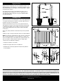
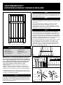
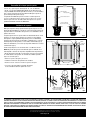
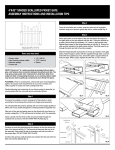
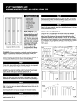
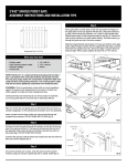
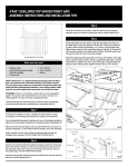
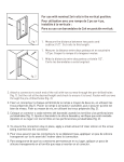
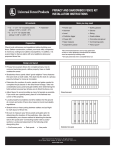
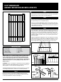
6'X42" WINDHAM GATE
ASSEMBLY INSTRUCTIONS AND INSTALLATION TIPS
Step 2
Place the groove of the top rail down firmly over the top of the pickets
and position rail so that it's flush on both ends (fig. 2).
Step 3
Lay two of the horizontal rails across the pickets so the notched rails
line up with the grooves on the pickets (fig. 3).
Using a non-marring rubber mallet, tap the horizontal rail, locking the
notched rail into the pickets. Repeat this process with the next notched
rail. Carefully flip the panel over and install remaining horizontal rails as
outlined in the previous step.
Step 4
Place gate jambs on both sides of the rails and place the hinges in the
center of the fence rail. Using the bracket as a guide, drill the three (3)
necessary ¼" holes for the bracket bolts. Repeat these steps for the
hinged brackets as well (fig. 4). Ensure the rails are fully inserted in the
jamb before drilling. The bolts need to go through the jamb and rail to
function properly.
Slide the hinged bracket and bracket on the top and bottom of the gate
jambs. Attach hinges to jambs with the supplied through bolts. Connect
bolts with the supplied cap nuts. Ensure the gate is square before all
bolts are tight. When square, tighten all bolts with a 7/16" wrench.
Actual size: 68-1/2"h x 42-1/2"w
Items you may need:
• Soapy water
•Non-marring
rubber mallet
• Wooden wedge
• Power drill
• 1/4" drill bit
• 7/16" wrench
•Shims
fig. 1
NOTE: PicketLock™ is a patent-pending technology that provides
a glue- and fastener-free connection between the pickets and
rails. You may spray soapy water onto components to help them
slide more easily into their corresponding channels. A non-marring
rubber mallet may also be used to gently tap components more
firmly into place.
PLANNING: Prior to construction, check with your local regulatory
agency for special code requirements in your area. Contact your
utility supplier to locate and mark underground lines.
fig. 2
Careful planning and measuring of your fence project is essential,
as moving posts after the concrete sets is extremely difficult.
Step 1
Find a clean surface for gate panel assembly. Beginning with the
starter picket, lay all pickets in the same direction and connect them
so the tongue side fits into the groove side (fig. 1).
fig. 4
fig. 3
Digging Post Holes
Dig post hole for the hinge post 18" to 24" in diameter and 36" to 42"
deep (depending on local ordinance or expected frost depth in winter).
We recommend that you insert a piece of 4x4 treated lumber to support
the gate hinge post (fig. 5).
Check measurement of gate. Actual width of the gate is 42-1/2".
The inside post-to-post dimension is 43-3/4". This will give you a
5/8" gap on both sides of the gate to the posts. DOUBLE-CHECK
ALL MEASUREMENTS!
Installing the Gate
Measure to be sure you can install the gate to the post with approximately
a 2" gap from the ground to the bottom of the gate. Align the rails on
the gate to the rails on the fence panels.
Hang the gate between the posts. Use a 5/8" spacer between the
gate and the posts (fig. 6). Secure in place with shims under the gate
or clamp the gate jamb to the post. Make sure the gate is level and
square. Attach hinge brackets to the gate post with the provided
screws (fig. 7).
fig. 5
Remove any clamps and shims. Attach latch using screws provided
(fig. 8).
Install a post cap on each post using PVC cement or an exterior adhesive.
NOTE: The gate latch is designed to be used on the left- or right-hand
side of the gate, depending on customer preference or design. The
latch is assembled, ready to be installed on the right-hand side of the
gate. If you desire to switch the latch follow these simple steps:
• Remove the 2 shoulder bolts and spring
• Change the orientation of the striker
• Reattach the spring and insert the shoulder bolts
fig. 6
•Shoulder bolts must be fully tightened. Thread-locking adhesive
is recommended.
fig. 7
fig. 8
THE DIAGRAMS AND INSTRUCTIONS IN THIS BROCHURE ARE FOR ILLUSTRATION PURPOSES ONLY AND ARE NOT MEANT TO REPLACE A LICENSED PROFESSIONAL. ANY CONSTRUCTION OR
USE OF THE PRODUCT MUST BE IN ACCORDANCE WITH ALL LOCAL ZONING AND/OR BUILDING CODES. THE CONSUMER ASSUMES ALL RISKS AND LIABILITY ASSOCIATED WITH THE
CONSTRUCTION OR USE OF THIS PRODUCT. THE CONSUMER OR CONTRACTOR SHOULD TAKE ALL NECESSARY STEPS TO ENSURE THE SAFETY OF EVERYONE INVOLVED IN THE PROJECT,
INCLUDING, BUT NOT LIMITED TO, WEARING THE APPROPRIATE SAFETY EQUIPMENT. EXCEPT AS CONTAINED IN THE WRITTEN LIMITED WARRANTY, THE WARRANTOR DOES NOT
PROVIDE ANY OTHER WARRANTY, EITHER EXPRESS OR IMPLIED, AND SHALL NOT BE LIABLE FOR ANY DAMAGES, INCLUDING CONSEQUENTIAL DAMAGES.
©2014 Universal Forest Products, Inc. All rights reserved.
2801 E. Beltline NE, Grand Rapids, MI 49525 800.332.5724 7811_7/14
www.ufpi.com
PUERTA WINDHAM DE 6'X42"
INSTRUCCIONES DE MONTAJE Y CONSEJOS DE INSTALACIÓN
Paso 2
Coloque la ranura del barandal superior hacia abajo firmemente sobre
la parte superior de las estacas y posicione el barandal para que esté
igual en ambos extremos (fig. 2).
Paso 3
Coloque dos de los barandales horizontales a través de las estacas de
modo que los barandales con ranuras se alineen con las ranuras de las
estacas (fig. 3).
Con un mazo de goma que no deje marcas, golpee suavemente
el barandal horizontal, uniendo el barandal con ranuras en las
estacas. Repita este proceso con el siguiente barandal con ranuras.
Cuidadosamente voltee el panel e instale los barandales horizontales
que quedan como se indica en el paso anterior.
Paso 4
Coloque las jambas de la puerta en ambos lados de los barandales y
coloque las bisagras en el centro del barandal de la cerca. Utilizando el
soporte como guía, perfore los tres (3) agujeros necesarios de 1/4" para
los pernos del soporte. Repita estos pasos para los soportes de bisagras
también (fig. 4). Asegúrese de que los barandales estén completamente
insertados en la jamba antes de perforar. Los pernos tienen que ir a través
de la jamba y el barandal para que funcionen correctamente.
Tamaño real: 68-1/2" de alto x 42-1/2" de ancho
Deslice el soporte de bisagra y el soporte en la parte superior e inferior
de las jambas de la puerta. Fije las bisagras en las jambas con los
pernos suministrados. Conecte los pernos con las tuercas ciegas
suministradas. Asegúrese de que la puerta esté cuadrada antes de
ajustar todos los pernos. Cuando esté cuadrada, ajuste todos los
pernos con una llave inglesa de 7/16".
Artículos que usted puede necesitar:
• Agua jabonosa
•Mazo de goma
para no dejar marcas
• Cuña de madera
• Taladro eléctrico
• Broca de 1/4"
• Llave inglesa de 7/16"
•Cuñas
fig. 1
NOTA: PicketLock™ es una tecnología cuya patente está en trámites
que proporciona una conexión libre de pegamento y sujetadores
entre las estacas y barandales. Usted puede rociar agua jabonosa
en los componentes para ayudar a que se deslicen más fácilmente
en sus correspondientes canales. Un mazo de goma que no deje
marcas también se puede utilizar para golpear suavemente los
componentes para fijarlos más firmemente en su lugar.
PLANIFICACIÓN: Antes de la construcción, consulte con su
organismo regulador local para los requisitos especiales de
códigos en su área. Póngase en contacto con su proveedor de
servicios básicos para localizar y marcar las líneas subterráneas.
fig. 2
fig. 3
Tornillo del tope de puerta
Tope de puerta
La cuidadosa planificación y medición de su proyecto de cercas
es esencial, ya que mover los postes después de que el concreto
se asienta es extremadamente difícil.
Paso 1
Encuentre una superficie limpia para el montaje del panel de la puerta.
Comenzando con la estaca de arranque, ponga todas las estacas en
la misma dirección y conéctelas de manera que el lado de la pestaña
encaje en la ranura lateral (fig. 1).
Tuercas
ciegas
Soportes de
bisagra
Pernos pasantes
Jambas de puerta
fig. 4
Soportes
Excavación de los hoyos para los postes
Apertura
de puerta
Cave un hoyo para el poste de bisagra de 18" a 24" de diámetro
y de 36" a 42" de profundidad (dependiendo de la ordenanza local
o la profundidad de la helada esperada en invierno). Le recomendamos
que se inserte una pieza de 4x4 de madera tratada para soportar el
poste de bisagra de la puerta (fig. 5).
Poste de bisagra
Poste de pestillo
Pieza de madera de 4x4
Compruebe la medida de la puerta. El ancho real de la puerta es
42-1/2". La dimensión interior poste-a-poste es de 43-3/4". Esto le
dará un espacio de 5/8" de ambos lados de la puerta a los postes.
¡VUELVA A REVISAR TODAS LAS MEDIDAS!
18"- 24" de diámetro.
Hoyo lleno de concreto
Instalación de la puerta
Mida para asegurarse de que puede instalar la puerta al poste con una
brecha de aproximadamente 2" desde el suelo hasta la parte inferior de
la puerta. Alinee los barandales de la puerta con los barandales de los
paneles de la cerca.
Cuelgue la puerta entre los postes. Utilice un distanciador de 5/8" entre
la puerta y los postes (fig. 6). Asegure en su lugar con cuñas debajo
de la puerta o sujete la jamba de la puerta al poste con abrazaderas.
Asegúrese de que la puerta esté nivelada y cuadrada. Fije los soportes
de bisagra al poste de la puerta con los tornillos suministrados (fig. 7).
36" a 42"
Bases de apoyo
fig. 5
Poste de bisagra
Plancha de cerradura
Pestillo
Poste de
pestillo
Retire las abrazaderas y las cuñas. Fije el pestillo utilizando los tornillos
suministrados (fig. 8).
Instale el tope del poste con cemento de PVC o un adhesivo exterior.
NOTA: El pestillo de la puerta está diseñado para ser utilizado en el
lado izquierdo o derecho de la puerta, dependiendo de la preferencia
o diseño del cliente. El pestillo está montado y listo para ser instalado
en el lado derecho de la puerta. Si usted desea cambiar el pestillo,
siga estos sencillos pasos:
Distanciador
de 5/8"
• Quite los 2 pernos de ajuste y el resorte
• Cambie la orientación de la plancha de cerradura
• Vuelva a colocar el resorte e inserte los pernos de ajuste
Nivel del suelo
•Los pernos de ajuste deben estar bien apretados.
Se recomienda un adhesivo fijador de roscas.
fig. 6
Soportes de bisagras
Centrar en los barandales
superiores e inferiores
Pestillo
fig. 7
Plancha de cerradura
fig. 8
LOS DIAGRAMAS E INSTRUCCIONES DE ESTE FOLLETO SON PARA FINES ILUSTRATIVOS SOLAMENTE Y NO ESTÁN DESTINADOS A REEMPLAZAR A UN PROFESIONAL MATRICULADO.
CUALQUIER CONSTRUCCIÓN O USO DEL PRODUCTO DEBEN ESTAR DE ACUERDO CON TODOS LOS CÓDIGOS LOCALES DE CONSTRUCCIÓN O DE ZONIFICACIÓN. EL USUARIO ASUME
TODOS LOS RIESGOS Y RESPONSABILIDADES ASOCIADOS CON LA CONSTRUCCIÓN O EL USO DE ESTE PRODUCTO. EL USUARIO O CONTRATISTA DEBEN TOMAR TODAS LAS MEDIDAS
NECESARIAS PARA GARANTIZAR LA SEGURIDAD DE TODAS LAS PERSONAS INVOLUCRADAS EN EL PROYECTO, INCLUIDO, ENTRE OTROS, EL USO DEL EQUIPO DE SEGURIDAD
APROPIADO. A EXCEPCIÓN DE LO CONTENIDO EN LA GARANTÍA LIMITADA POR ESCRITO, EL GARANTE NO PROPORCIONA NINGUNA OTRA GARANTÍA, YA SEA EXPRESA O TÁCITA, Y
NO SERÁ RESPONSABLE DE NINGÚN DAÑO, INCLUIDOS DAÑOS CONSECUENTES.
©2014 Universal Forest Products, Inc. Todos los derechos reservados.
2801 E. Beltline NE, Grand Rapids, MI 49525 800.332.5724 7811_7/14
www.ufpi.com