Transcript
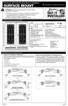
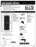
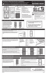
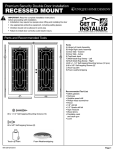
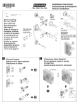
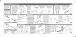
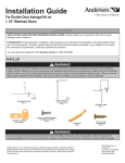
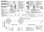
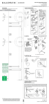
Steel All Season Security Door Installation:
For Waterford and Coventry models
STOP
RECESSED MOUNT
PLEASE READ ALL INSTRUCTIONS BEFORE YOU BEGIN INSTALLATION.
We recommend that you have a helper for this installation.
Parts and tools required
B
B
Included:
A) Door/hinge-side Z-bar
jamb assembly
B) Top/Head jamb
C) Lock-side Z-bar jamb
D) Bug sweep/expander bar
E) Door panel
F) Self-storing glass
sub-assembly
G) Fiberglass screen
K
G
A
E
C A
E
C
F
8.5 mm x 11mm
Top/Head Jamb Bolt (2)
I
Fiberglass screen
Mortise Lockset
and Hardware
H
D
Waterford
D
- OR -
Coventry
Self-storing glass
sub-assembly
Door closer
and windchain
2
door swing
1Fig. Determine
Fig. 1 - Your Steel All Season Security Door
is designed as an out-swing door and will
swing away from the house when opened.
The handle of primary door and security
door should be on the same side. Determine
which direction your security door should
swing and compare to the preset swing
of the product. If the door is already the
correct swing for your entry, skip to Step 5.
Otherwise, follow Steps 2 & 3 to reverse the
hinge side for proper door swing direction.
Note: All doors come packaged as left
hinge, right open.
Recommended Tools:
Measuring tape, pencil, level, power drill and 1/8" drill bit, hammer,
hack saw, 3/8" wood chisel, flat-blade screwdriver, Phillips-head
screwdriver, safety glasses, wood shims, utility knife, saw horses
J
Glass panel
H) Glass panel
I) Mortise lockset and hardware
J) Door closer and windchain
K) Head jamb bolt
2 Remove self-storing glass sub-assembly
Left hinge
Fig. 2 - Remove 14 screws holding selfstoring glass sub-assembly in place.
Right hinge
TOP
Self-storing glass sub-assembly
Self-storing glass
sub-assembly
F
Fig. 3 - With two people, carefully lift
at top and bottom of self-storing glass
sub-assembly and set aside.
G
Remove bottom bug sweep/expander
bar (D) and set aside.
Fig. 1
TOP
F
H
Fig. 2
D
BOTTOM
Bug sweep/
expander bar
BOTTOM
Fig. 3
3 Remove and reverse fixed glass and screen panels
Fig. 4 - Remove screws holding fixed fiberglass screen (G) and
screws holding fixed glass panel (H) in place.
G
Fig. 5 - Carefully remove glass and screen panels (G & H) and swap
the position of the panels.
H
TOP
G
H
TOP
TOP
G
Fig. 6 - The screen panel should be where the glass panel was and
vice versa. Screw panels into position using screws from fig. 4.
Fig. 7 - Carefully rotate self-storing glass sub-assembly 180o and
set back into position. Reattach screws from fig. 2.
Note: Glass panel should be in opposite position from when it was
originally removed.
H
Fig. 4
BOTTOM
Fig. 5
BOTTOM
BOTTOM
Fig. 6
Fig. 7
4 Reverse door top and side jambs to change swing direction if needed
Fig. 8- Remove head/top jamb (B) from top of in each of the five hinges but do not over tighten.
TOP
door (E) by unscrewing the two Phillips-head
Fig. 10 - From lock side of the door, remove the
jamb bolts (M). Set aside while jambs are
B
Phillips-head screw from each pre-hang clip (DO
readjusted.
NOT REMOVE PLASTIC CLIP FROM DOOR).
Slide lock side Z-bar jamb (C) toward what is
Fig 9 - Open hinge-side of Z-bar jamb (A)
E
now the bottom of the door to the next pre-drilled
to expose hinge screws. Remove the two
hole below; replace the Phillips-head screws in
Phillips-head screws from each of the five
hinges. Slide hinge-side Z-bar jamb (A) toward each of the two pre-hang clips but do not tighten.
Once removing the top/head
what will now be the bottom of the door
Fig. 11 - Move top/head jamb (B) to what is now
jamb, this will now be the
(where the top/head jamb (B) was in (Fig. 1)
the top of the door. Tighten the screws for the
BOTTOM of the door
to the next pre-drilled hole. Be sure holes are
hinges and pre-hang clips. Reinstall top/head
aligned. Replace the two Phillips-head screws
Fig. 8
jamb (B) with existing screws.
5
Slide hinge side jamb
upward and attach screws
Slide lock side jamb upward
and attach screw
C
A
A
C
Bottom
Pre-hang
clip
Fig. 9
Reattach top/head jamb to
opposite end where it was
removed (Fig. 1)
A
B
C
E
This will now be the TOP
of the door
Fig. 10
Top
Fig. 11
Fit Steel All Season Security Door to your opening
Fig. 12 - Measure the inside height of the opening where the door is to be installed.
Fig. 13 - Subtract 1/8" from the height – this is your trim length. Starting at the top
of the door, measure and mark each vertical Z-bar jamb (A & C) piece at your trim
length. Cut the bottom of each of the jambs.
Measure opening
height and substract
1/8" (For example, if
opening is 80", your
jamb cut height will be
79-7/8").
Cut both Z-bar
jambs (A & C) at
the measurement
determined in Fig. 3.
IMPORTANT: Be sure
to measure from the
top before cutting.
Cut here
Top
Fig. 12
6
Bottom
Fig. 13
Mount Steel All Season Security Door
Fig. 14 - Place the door into the opening making sure it is level and plumb. With the
door in place, drill a 5/32" hole approximately 1/2" deep through each of the predrilled holes in the Z-bar jambs (A & B) and into the doorway trim. Starting with holes
(1-3), insert mounting screws and tighten.
Fig. 15 - Remove screws on pre-hang brackets and remove brackets. Through the
remaining holes in the Z-bar jambs (A & C) and top/head jamb (B), drill a 5/32" hole
approximately 1/2" into the doorway trim. Insert mounting screws into holes (4-12)
and tighten.
10
11
4
B
A
C
12
B
13
6
A
C
14
7
1
3
15
2
16
8
Fig. 16 - Open door. On the inside of hinge side z-bar jamb (A) insert mounting
screws into holes (13-17) and tighten. Close and open door to ensure proper fit,
adjust if necessary.
5
Fig. 14
Fig. 15
17
9
Fig. 16
7 Install the hardware and door closer
To install, follow the manufacturer’s instructions included with the door closer, windchain, and handleset hardware. (2-3/8" backset handle must be purchased separately)
8 Install bug sweep/expander bar
Fig. 17 - With the door open, fit the
bug sweep/expander bar (D) onto
the bottom of the door. Close the
door and position the bug sweep/
expander bar so that the bar fits
snugly against the threshold but
does nor restrict door operation.
From inside the door, drill 1/8"
holes through the bug sweep/
expander bar and secure the
expander bar to the door with
D
the provided #6 x 3/4"screws.
Fig. 17
9
Final touch up and maintenance suggestions
Fig. 18 - After installation is complete, apply touch
up paint (not included) to screws and/or surface of
door to cover any minor scratches that may have
resulted during installation.
Fig. 19 - Open latch at bottom
of glass panel and using
handle at top of glass panel,
raise or lower inner glass panel
to desired location.
Caulk around the outside of the all season security
door jamb frame, using paintable caulk, and paint to
the desired color.
To clean your door use a mild soap and water
solution or window cleaner. Do not use any abrasive
cleaners on any part of your door– this will damage
the powder-coat finish and void your paint warranty.
10 Self-storing glass operation
Fig. 18
Your Unique Home Designs® Security Door is warranted against manufacturing defects of the welded frame and pickets for as long as you own the home upon which the door is properly installed.
If structural defects occur in these areas we will, at our discretion, repair or replace the door. Replacement items may vary in style due to changes in suppliers and product. In addition, the paint
finish is warranted not to blister, crack, or fade for one year from the purchase date. Damage due to rust is excluded from this warranty. Screens, glass and hardware are also excluded from this
warranty. This warranty does not cover damage caused by vandals, break-ins, or attempted break-ins. This warranty is voided if the product is modified in any way. Any problem caused by abuse,
misuse, failure to maintain warranted item properly, adjustments due to settling of the structure that the product is mounted on, or acts of God, are not covered. Unique Home Designs® assumes no
responsibility for labor costs of any kind for removal, replacement of parts, repairs, or reinstallation. To make a claim under this warranty, send a brief written description of the problem, a picture of
the problem, proof of purchase, and your contact information to: Unique Home Designs, 973 N. Colorado Street, Gilbert AZ. 85233 Attn: Warranty Claims
Fig. 19
VIEW INSTALLATION VIDEOS
AND LATEST INFORMATION AT
MK818 10252012