1
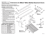
Bilco Sloped Wall Basement Door
Installation
Instructions
Call Customer Service at (800) 854-9724
www.bilco.com
The Bilco Door is designed to operate with ease, keep your stairs
dry and free of debris, and deliver many years of trouble free service when installed in accordance with these instructions. Some
installations may require that you drill and cut metal. Be sure to
use the proper tools, wear proper safety equipment and clothing,
and secure any item to be drilled or cut to a stable work surface.
For a satisfactory installation, read the following
Instructions before the job begins:
• Foundation Requirements: SECTION A, page 2
• Foundation Plates: SECTION B, page 2
• Door Assembly and Installation: SECTION C, page 4
The names of the door parts referred to in the instructions appear
below:
Note: The Bilco Sloped Wall Basement Door must be installed
square and level on a structurally sound foundation.
Minimum headroom requirements
will vary according to each areaway.
To determine headroom for your
areaway, refer to the chart below and
find the net clear opening for your
door size. Measure from the lower
end of your sidewall up to the dimension on the chart. Drop a plumb line
from this point to the stairs. This is
the minimum headroom of your
areaway.
Door Size
Net Opening
SLW 3641
SLW 4651
SLW 4751
SLW 5055
SLW 5459
57"
57"
67"
60"
67"
Torsion Rods
Hinge
Header
Slide Bolt Lock
(Optional Keyed
Lock Available)
Flashing Strip
Right
Side
Piece
Right Door
Operating Arm
Safety Latch
Left Door
Left
Side Piece
Support
Bracket
Sill
Depending on the installation, the following tools
and material may be required:
Hammer and Nails
Sledge Hammer
Masonry Chisel
Circular Saw
Jig Saw
Electric Drill
7/16", 9/16" Wrenches
Flat blade Screwdriver
Work Gloves
Eye Protection
(1) Tube Silicone Caulk
Pry Bar
Level
Tape Measure
Abrasive Metal Cutting Blade
Metal Cutting Jig Saw Blade
1/4” + 9/32" High Speed Drill Bits
1/4" Carbide Masonry Drill Bit
Hack Saw
Shovel and Trowel
Mortar Tub
Hearing Protection
Printed in U.S.A. © Copyright, 2010, The Bilco Company, New Haven, CT 06505
Call the BILCO HELP LINE
For Installation Information (800) 854-9724
weekdays from 9 AM to 5 PM EST.
CAUTION
When the doors are open for access, the area should be personally guarded to prevent anyone from falling down the stairs.
Doors should be closed and locked when not in use.
KEEP OFF DOORS TO AVOID INJURY
Surface may be slippery. In extreme conditions steel in the
summer sun can become hot and cause injury. White enamel
or other light color finish paint will reflect sunlight and reduce
the temperature of the metal. KEEP OFF DOORS
7/10
1MSC302 REV 6.0
SECTION A
SECTION B
FOUNDATION REQUIREMENTS
OPTIONAL FOUNDATION PLATES
Bilco foundation plates are available from your Bilco dealer. See
size chart on page 3 for dimensions. Foundation plates are
installed on top of areaway foundation sidewalls to:
Level surface no loose
masonry
areaway appearance
• improve
rough masonry and small holes, and span voids in brick
• cover
and concrete block
the inside width of the areaway foundation
• reduce
• for corner installations with one side supported by house
Level
Sound sidewalls
1) How to Cut Foundation Plates
Foundation plates must be cut to fit areaway. For best appearance,
cut ends that go against house and scribe 1-3/4” side to fit flush
against house. For safety, work gloves, eye and hearing protection
and long sleeves are recommended. Do not cut near flammable
materials. Firmly clamp plate to a solid surface. Cut with a circular saw and an abrasive metal cutting blade, a reciprocating saw or
jig saw and a metal cutting blade with 18 to 24 teeth per inch, or
use a hacksaw. Do not force blade through steel.
Sill 2" to 4"
above grade
FIGURE - 1
To operate properly, the Bilco Door must be square and firmly
anchored to a sound foundation. Each sloped foundation sidewall must:
be solid, with no loose or crumbling masonry
have a uniformly flat and level surface on which to anchor the
Bilco Door
be uniformly level with the opposite sidewall
The sill must be 2" to 4" above grade.
If repairs are needed, they should be done before the Bilco
Door is installed. See the following guidelines, HOW TO REPAIR
MASONRY SIDEWALLS.
HOW TO REPAIR MASONRY SIDEWALLS
1) Mortar Joints Loose or Crumbling
Remove loose material and crumbling mortar to solid masonry, or
a depth of one inch, whichever is greater. Clean all surfaces with
water. Refill joints with pre-mixed, bagged mortar cement, following instructions on mortar bag. See your masonry supply dealer for
complete information.
2) Sidewalls Need Reinforcing and Resurfacing
Apply fiberglass surface bonding cement to both sides of the walls
to reinforce, resurface and waterproof them. Several brands are
available from your mason supply dealer. Surface preparation and
application methods are critical. Follow manufacturer’s instructions for the brand you use.
2) How to Install Foundation Plates
Foundation plates are 84” long. Select correct width for your foundation, determine overall length, and cut to fit (note: foundation
plates are installed with 1-3/4" flange on outside of sidewall, see
Figure - 2 below). If areaway is longer than 84”, overlap two foundation plates. To do this, place a full length foundation plate at low
end of each sidewall and cut a piece long enough to fill gap and
overlap first plate by at least one inch, see Figure -2 below.
Foundation plates must be level. If necessary, level top of sidewalls
with mortar before installing foundation plates. Foundation plates
must be firmly anchored to foundation with 1/4” lead or steel
masonry anchors (not supplied). If door frame overlaps foundation
by at least 2", the foundation plates and door frame can be
anchored to the foundation at the same time, using the nail-in
anchors in door hardware. Assemble door frame per SECTION C
Step - 1. Place foundation plates on foundation and position door
frame on top of foundation plates per Step - 2. Using predrilled
holes in door side pieces as a guide, drill 9/32" holes with a metal
drill bit through foundation plates. Change to a 1/4” carbide tipped
masonry bit and drill 2-1/4” deep holes into solid masonry. If foundation walls are concrete block or brick, drill holes in solid portions
of the masonry. Follow Step 3 to anchor door to foundation. If door
frame does not overlap foundation by at least 2", anchor foundation
plates to areaway foundation using 1/4” nail-in anchors provided
with the door hardware. Locate anchors at least 6" from the inside
edge of the foundation plate , space 18" apart, and anchor door
frame to the foundation plates with 1/4” round head bolts and nuts
(purchased separately). It may be necessary to chisel pockets in
foundation for bolts and nuts.
3) Top Surface of Sidewalls is Rough, Not Level.
Prepare surface for new concrete cap by removing all loose material down to solid masonry, rough up surface and clean with water.
Apply masonry bonding agent and pour new concrete cap using
bagged, pre-mixed concrete mix. Check with your mason supply
dealer for best bonding agent and concrete mix. Form a level surface on top of each sidewall and be sure both walls are level with
each other. Pressure treated wood may be used instead of concrete. It must be level, caulked and firmly anchored to the foundation. You may wish to use Bilco Foundation Plates, available
from your Bilco Dealer, to finish the top of the sidewalls. See SECTION B for information.
4) Single Course Brick Sidewalls
Brick sidewalls that are only one brick wide may not be strong
enough to support the Bilco Door. They should be reinforced with
another course of brick, or by a concrete wall poured against the
brick wall and tied into it with wall ties.
Page 2
To increase length of foundation
plate, place full length plate on
foundation, cut a piece to fit and
overlap lower plate by 1".
Anchor plates
with 1/4"
masonry
anchors
FIGURE - 2
Foundation Plate Size Chart
Model
Width
Length
Height
FP5
FP8
FP11
FP14
5"
8"
11"
14"
84"
84"
84"
84"
1-3/4"
1-3/4"
1-3/4"
1-3/4"
Foundation Plate
3) How to Reduce Inside Width of Areaway
Select foundation plates that are wide enough to cover the top of
the foundation and reduce the width of the areaway for proper fit
of the Bilco Door. Figure - 4 shows an areaway with 8" sidewalls
and 60" inside width. Figure - 5 shows two 11" foundation plates
used to reduce the inside width to 54". If necessary, you can use
a different width foundation plate on each sidewall for proper fit.
Cut the foundation plates to the proper length, and drill 9/32"
holes, at least 6" from the inside edge of the foundation plate,
every 18". Change to a 1/4” carbide tipped masonry drill bit and
use the holes in the foundation plates as a guide to drill 1/4” x 21/4” holes in the foundation. Anchor foundation plates to solid,
level masonry with 1/4” nail-in anchors provided in the door hardware package. If the foundation plates overhang the foundation
by more than 6", fasten pressure treated wood or angle iron to the
inside of the masonry foundation so that it supports the entire
length of foundation plate. Assemble the door frame per SECTION
C, Step - 1. Position frame on firmly anchored foundation plates
per Step 2. Verify that door frame is level and square. Using
predrilled holes in door frame as a guide, drill 9/32" holes in the
foundation plates using a metal drill bit. Apply bead of silicone
caulking compound under door frame where it meets foundation
plates and around each anchor hole. Anchor door frame to foundation plates using 1/4” x 1/2” bolts and 1/4” hex nuts (not supplied).
4) How to Install When Areaway is in a Corner With One Side
Supported by House
Select a foundation plate wide enough to allow the door leaf to
open completely and safety latch to engage. Cut foundation plate
to length, drill 9/32" holes every 18" in 1-3/4” flange, and place it
against house with 1-3/4” flange facing up, per Figure - 6. Be sure
that foundation plate is level with opposite areaway sidewall. Mark
hole locations on house foundation. If necessary remove siding so
that foundation plate can be anchored directly to house foundation
or sheathing. Drill 1/4” x 1-1/2” deep holes in house foundation.
Fasten foundation plate to house foundation through 1-3/4”
upturned flange. For masonry construction, use 1/4” x 1-1/2”
masonry lags and shields (purchased separately). For wood construction, use wood screws. Caulk foundation plate where it
meets house with silicone caulk (not supplied). Go to SECTION C
for Door Assembly and Installation Instructions.
Painting Instructions
IMPORTANT: Door must be painted within forty-five (45) days
of installation. The Bilco Basement Door and optional extension panels are supplied with a uniform baked-on SherwinWilliams primer finish. Prior to finish painting, clean all surfaces thoroughly and apply a finish coat of acrylic latex in
white or light color to all interior and exterior steel surfaces. A
quart is sufficient for one finish coat. Note: Bilco does not recommend the use of Rust Oleum products. Optional stair
stringers and foundation plates are galvanized steel but can
be painted for aesthetic purposes. If painted, a metal primer
must be used prior to applying the finish coat of paint.
FIGURE - 3
76"
8"
FIGURE - 4
76
"54"
11"
FIGURE - 5
Rubber Bumper Installation
IMPORTANT: Use rubber bumpers to protect door finish.
After the finish paint has dried, install two rubber bumpers in
the holes on the outside edge of each door. Bumpers are
installed by twisting the small end into the hole until it is fully
seated. Bumpers cushion the doors in the open position and
protect the finish paint.
FIGURE - 6
Page 3
8"
60"
11"
SECTION C
SLW Side Piece
DOOR ASSEMBLY AND INSTALLATION
CAUTION: The BILCO Basement Door sheds water in all normal
conditions only when installed and caulked in accordance with
these instructions. If there are no rain gutters above, a diverter
must be installed to prevent roof water from flowing directly onto
the BILCO Door.
SLW
Support
Bracket
A
Sloped sidewalls must be structurally sound and level for proper
operation of your new Bilco Door. Remove the old door and check
sidewalls (see Figure - 1 on page 2). If no repairs are required,
begin your installation with Step - 1.
A 5/16"-18 x 3/4" Long
STEP - 1 Assemble Door Frame
B Locknut
The Bilco SLW basement door consists of nine parts (see front
cover for part names), four torsion rods with cams ( Note: Model
SLW3641 contains two torsion rods only), and the hardware package*. Begin assembly of frame by attaching support brackets to
side pieces with carriage bolts and locknuts per Figure 7. Apply a
bead of caulking (not provided) to each header end plate per
Figure - 8A. Attach header to side pieces with four 1/4” round head
bolts and nuts. (Note: to determine SLW left side from right side,
position so that the two holes in the upturned flange of each side
are at the bottom, see Figure - 8C). Header end plates must be
under the side pieces, with bolt heads facing out, per Figure - 8B.
Tighten bolts until caulking squeezes out. Remove excess caulk
and use it to fill inside joint, per Figure - 8B. Attach sill to side
pieces with four 1/4” flat head bolts. Nuts must face inside, per
Figure - 8C. Hand tighten.
Carriage Bolt
FIGURE - 7
B
Left
side piece
Nuts under
5/16" x 3/4" carriage bolts and locknuts
1/4” x 5/8" round head bolts and nuts
1/4” x 1/2” flat head bolts and nuts
5/16" x 1-1/4” hinge pins with cotter pins
1/4” x 2" nail-in anchors
rubber door bumpers
vial lubricant
Right End View
Round heads of
bolts outside
Header
Fill pocket and seal
vertical joint with
caulking compound
both ends of header
C
Flat heads of
bolts outside
Nuts
inside
Sill
Right
side piece
A
* Hardware
(10)
(6)
(4)
(4)
(15)
(4)
(1)
B
FIGURE - 8
Fill pocket
Place bead
of caulking
compound on
both end plates
before bolting
header to side pieces
Measure Diagonals
STEP - 2 Position Door Frame on Foundation
Be sure masonry foundation is in good condition and level, clean
and dry. Door side pieces must overlap foundation sidewalls by at
least 2" on each side. If overlap is less than 2", install Bilco
Foundation Plates according to SECTION B before door frame is
placed on foundation. Move assembled door frame into place on
foundation. For proper door operation, the frame must be level
and square. To square, see Figure - 9 and measure diagonals
from top right inside corner to bottom left inside corner of
frame and from top left inside corner to bottom right inside
corner. Move lower end of frame to left or right until diagonal
measurements are equal. Adjust sill by pivoting until level and
tighten bolts. To adjust sill on extremely high sidewalls, it may be
necessary to remove the upper sill bolts.
*
* Minimum
2" overlap
with sidewalls
FIGURE - 9
STEP - 3 Anchor Door Frame To Foundation
The door frame must be securely anchored to a sound masonry
foundation, or to foundation plates that are firmly anchored to the
foundation. No part of the Bilco Door should be covered with concrete. Apply bead of silicone caulking compound (not supplied) to
clean, dry masonry foundation (or optional foundation plates)
underneath door frame, per Figure - 10. Verify that door frame is
level and square. Using pre drilled holes in side pieces and sill as
a guide, drill holes into the foundation 2-1/4" deep using a 1/4”
carbide tipped masonry bit. Apply silicone caulk around each
anchor hole and insert nail-in anchors, making sure anchor heads
contact door frame and are embedded in caulk. Hammer nailpins
down until flush.
Apply
silicone caulk
under frame
FIGURE - 10
Page 4
er
lowame ls
e
v
r
a
Mo d of f gon
en til dia al
un equ
are
STEP - 4 Install Flashing Strip
Flashing Strip
Flashing strip must overlap the header by at least 3/4".* To install
the flashing strip, remove the two top bolts from the door header.
Position flashing strip on door with upturned flange against house,
per Figure - 11A. Fit upturned flange under siding, per Figure 11B, and apply a bead of silicone caulk under perimeter of flashing strip where it overlaps door header. Nail flashing strip to
sheathing or anchor to masonry with 1/4" concrete anchors purchased separately. Use holes in flashing strip as a guide and drill
two 9/32" holes through middle of door header, apply silicone
caulk around each hole and fasten flashing strip to door header
with 1/4" round head bolts and nuts. Drill one 9/32" hole at each
end of flashing strip through door side pieces, change to a masonry drill bit and drill 1/4" x 2-1/4" deep holes into the masonry.
Apply caulk around holes, insert nail-in anchors provided and
hammer nailpins down until flush with door frame.
A
3/4"
Minimum
Overlap
Clapboard
or Shingle
*If space between door header and house is greater than flashing
strip, or overlap is less than 3/4", extension panels are available
from your BILCO dealer in 6" and 12" widths.
STEP - 5 Install Doors
B
Flashing
(by others)
Caulk
1
1
1
2
2
2
Sheathing
1
Install right door per Figure - 12A by holding it vertically over right
side piece so that hinges fit into hinge brackets on side piece. Line
up holes in hinges with hinge pivot holes in brackets and insert
5/16" x 1-1/4" hinge pins and cotter pins. Install left door in same
manner.
Flashing Strip
Frame Construction
Section at Hinge
Upper
Hinge
Hinge
STEP - 6 Install Torsion Rods
There are two rods marked #1 and two marked #2. Markings can
be found on the plastic component on each rod. Each door
requires one #1 and one #2 torsion rod. (Note: Model SLW 3641
uses only two rods)
Before installing the rods, apply lubricant to plastic components
per sketch included with packet containing lubricant vial.
Door
Lubricate
(see note A)
Side piece
Hinge Bracket
Hole for Torsion Rod
Hinge Pivot Hole
A
Left door: Open left door so safety latch engages. Refer to
Figure - 12B and install rod #1 first, then install rod #2 so that it passes under rod #1. Insert “U” shaped end of rod #1 through hole in
upper hinge bracket of left side piece, as shown in the diagram.
Insert “L” shaped end of rod UP into the lower retainer. Insert “U”
shaped end of rod #2 through hole in lower hinge bracket of left side
piece, as shown in diagram. Insert the “L” shaped end of the rod
DOWN into the upper retainer. Rod #2 should pass under rod #1.
Right door: Open right door so safety latch engages. Refer to
Figure - 12C and install rod #1 first, then install rod #2 so that it passes under rod #1. Insert “U” shaped end of rod #1 through hole in
lower hinge bracket of right side piece, as shown in the diagram.
Insert “L” shaped end of rod UP into the upper retainer. Insert “U”
shaped end of rod#2‚ through hole in upper hinge bracket of right
side piece, as shown in diagram. Insert the “L” shaped end of the
rod DOWN into the lower retainer. Rod #2 should pass under rod #1.
To install torsion rods on model SLW3641 doors:
Lower
Hinge
B
C
Upper Hinge
This Rod passes
over Rod #2
Lower Hinge
Open door so safety latch engages. Refer to Figure - 12B (for
left door) or Figure 12-C (for right door) and insert “U” shaped end
of rod through hole in lower (for left door) or upper (for right door)
hinge bracket of side piece, as shown in the diagram. Insert the
“L” shaped end of the rod DOWN into the upper (for left door) or
lower (for right door) retainer.
This rod passes
under Rod #1
1
Upper
Hinge
This rod passes
under Rod #1
Lower Hinge
This Rod passes
over
Rod
#2
2
2
1
Retainers
Retainers
Inside View of Left Door
Inside View of Right Door
Optional Keyed Lock Available
Available for on-line purchase at
www.bilco.com.
FIGURE - 12
Page 5
Header
FIGURE - 11
Caution: Before closing doors, disengage safety latch on lower
hinge of each door.
To install torsion rods on all models except SLW3641:
2
Masonry Construction
How to correct installation errors or repair minor damage
Door not shedding water. If your Bilco basement door does not
shed water, look for and correct these installation errors.
1. Header end plates not caulked. Loosen header bolts and pry
plate down from below with a screwdriver. Push caulking in on
top of header end plate and retighten bolts. Fill pockets provided by protrusion of metal at each corner (see Figure - 8A & 8B ,
page 4).
2. Doors do not fully close. Stand on steps and slowly close each
door to see if the bottom flange of one or both is binding on the
concrete. Chip away or rub down excess concrete with mason's
stone so flange is not obstructed. Refer to instructions at right
for adjustments if required.
3. Sill not high enough. The masonry under the Bilco basement
door should be 4" higher than the surrounding grade and concrete should be level so water cannot accumulate in front of the
sill.
4. Water seeping between steel and masonry. The unit should be
caulked all around the exterior where the steel and masonry
meet, as well as where the unit joins the building wall. If side
pieces have been buried in concrete, the unit should be
removed and sidewalls recapped so assembly rests on top.
5. Blocked header channel. Make certain channel is clear. Any blockage in this channel will cause water to overflow the header.
direction of top of door, thus lowering it to line up with other door
(See Photo #1 below). If additional adjustment is necessary, remove
lower door, place lower end on ground and strike each hinge with a
hammer. This bends the hinges in the direction of the bottom of the
door, thus raising it to line up with other door.
Doors Not Seated Properly. If doors do not seat themselves properly or bounce slightly when in closed position, and bottom flanges
of doors are not obstructed by concrete in front of sill, apply lubricant such as WD-40 to hinges and cams, then refer to Step - 2 on
page 4 and: (a) check frame for level and square, and (b) from below
with door open three-quarters of the way, insert a screwdriver along
side of hinge and pull door down on it to a point where you feel
pressure of the screw driver relieving binding condition (See Photo
#2 below).
Hinge Damaged. A hinge can be bent downward by mishandling
during shipment or by someone trying to force the door closed
without releasing the hold-open safety latch, and as a result the
door does not fit properly on the frame. Such damage to a hinge
can be identified by a bump on the top of the door. To correct,
remove the door from the frame, place it on the ground with the
hinge side up and step downward on the hinge to bend the pivot
point back to its correct location. The other hinge on that door,
which has not been damaged, can be used as a guide in bending
the hinge back to the proper place (See Photo #3 below).
Doors Out of Alignment. This is caused by failure to align the
doors and square the frame as instructed. With doors closed, sight
across bottom. Remove door that is higher than the other. Hold vertically with top edge on the ground as shown. Strike each hinge
three or four solid blows with a hammer. This bends hinges in the
Door Warped or Bent. Place the end of the door on a block or bottom step of a nearby stairway, and step down on it with your foot.
The door can be bent back to the original shape very easily this way,
but when it is installed on the frame and supported all around it is
extremely strong and will not bend during everyday use (See Photo
#4 below).
Photo - 1
Photo - 2
Photo - 3
Photo - 4
Page 6