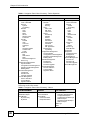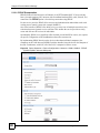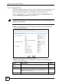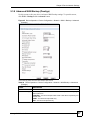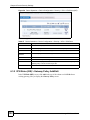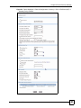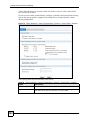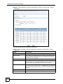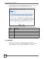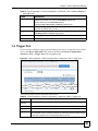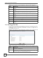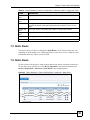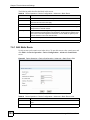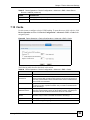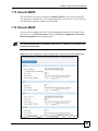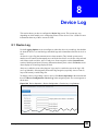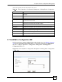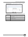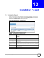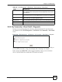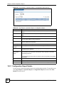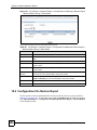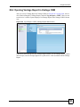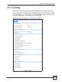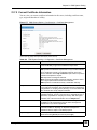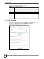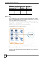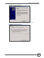
1
Vantage CNM
Centralized Network Management
User’s Guide
Version 3.0
11/2007
Edition 1
www.zyxel.com
About This User's Guide
About This User's Guide
"
The screens in Vantage CNM vary by device type and firmware version. The
examples in this User’s Guide use one of the most comprehensive examples
of each screen, not every variation for each device type and firmware version.
If you are unable to find a specific screen or field in this User’s Guide, please
see the User’s Guide for the device for more information.
Intended Audience
This manual is intended for people who want to configure Vantage CNM using the web
configurator. You should have at least a basic knowledge of TCP/IP networking concepts,
topology, and the devices you want to manage.
Related Documentation
• Quick Start Guide
The Quick Start Guide is designed to help you get up and running right away. It contains
information on setting up and connecting to your software.
• Web Configurator Online Help
Embedded web help for descriptions of individual screens and supplementary
information.
"
It is recommended you use the web configurator to configure the Vantage
CNM.
• Device User’s Guide
The User’s Guide for each device provides more information about the device, its features,
and its configuration.
• ZyXEL Web Site
Please refer to www.zyxel.com for additional support documentation and product
certifications.
User Guide Feedback
Help us help you. Send all User Guide-related comments, questions or suggestions for
improvement to the following address, or use e-mail instead. Thank you!
Vantage CNM User’s Guide
3
About This User's Guide
The Technical Writing Team,
ZyXEL Communications Corp.,
6 Innovation Road II,
Science-Based Industrial Park,
Hsinchu, 300, Taiwan.
E-mail: [email protected]
4
Vantage CNM User’s Guide
Document Conventions
Document Conventions
Warnings and Notes
These are how warnings and notes are shown in this User’s Guide.
1
"
Warnings tell you about things that could harm you or your device.
Notes tell you other important information (for example, other things you may
need to configure or helpful tips) or recommendations.
Syntax Conventions
• Vantage CNM may be referred to as “Vantage CNM” or the “product” in this User’s
Guide.
• Vantage Report may be referred to as “Vantage Report” or “VRPT” in this User’s Guide.
• A device that is managed by Vantage CNM may be referred to as the “ZyXEL device,”
“device,” or the “system” in this User’s Guide.
• Product labels, screen names, field labels and field choices are all in bold font.
• A key stroke is denoted by square brackets and uppercase text, for example, [ENTER]
means the “enter” or “return” key on your keyboard.
• “Enter” means for you to type one or more characters and then press the [ENTER] key.
“Select” or “choose” means for you to use one of the predefined choices.
• A right angle bracket ( > ) within a screen name denotes a mouse click. For example,
Maintenance > Log > Log Setting means you first click Maintenance in the navigation
panel, then the Log sub menu and finally the Log Setting tab to get to that screen.
• Units of measurement may denote the “metric” value or the “scientific” value. For
example, “k” for kilo may denote “1000” or “1024”, “M” for mega may denote “1000000”
or “1048576” and so on.
• “e.g.,” is a shorthand for “for instance”, and “i.e.,” means “that is” or “in other words”.
Vantage CNM User’s Guide
5
Document Conventions
Icons Used in Figures
Figures in this User’s Guide may use the following generic icons. Device icons are not an
exact representations of your devices.
6
Device (example)
Computer
Server
DSLAM
Telephone
Switch
Notebook computer
Router
Vantage CNM User’s Guide
Contents Overview
Contents Overview
Introducing Vantage CNM .......................................................................................................... 31
Introduction ............................................................................................................................ 33
GUI Introduction ........................................................................................................................ 35
Device Operation ................................................................................................................... 51
Load or Save Building Blocks (BB) ............................................................................................ 53
Device General Settings ............................................................................................................ 55
Device Network Settings ........................................................................................................... 59
Device Security Settings .......................................................................................................... 109
Device Advanced Settings ....................................................................................................... 185
Device Log ............................................................................................................................... 209
Device Configuration Management ......................................................................................... 213
Firmware Management ............................................................................................................ 235
License Management .............................................................................................................. 241
VPN Management ................................................................................................................. 247
VPN Community ...................................................................................................................... 249
Installation Report .................................................................................................................... 255
VPN Monitor ............................................................................................................................ 257
Monitor .................................................................................................................................. 265
Device Status Monitor .............................................................................................................. 267
Device HA Status Monitor ........................................................................................................ 269
Device Alarm ........................................................................................................................... 271
Log & Report ........................................................................................................................ 277
Device Operation Report ......................................................................................................... 279
CNM Logs ................................................................................................................................ 291
VRPT ....................................................................................................................................... 293
CNM System Setting ............................................................................................................ 297
CNM System Setting .............................................................................................................. 299
Maintenance ............................................................................................................................ 313
Device Owner .......................................................................................................................... 315
Vantage CNM Software Upgrade ............................................................................................ 317
License Upgrade ..................................................................................................................... 319
Vantage CNM User’s Guide
7
Contents Overview
About Vantage CNM ................................................................................................................ 321
Account Management .......................................................................................................... 323
Group ....................................................................................................................................... 325
Account .................................................................................................................................... 329
Troubleshooting ................................................................................................................... 333
Troubleshooting ....................................................................................................................... 335
Appendices and Index ......................................................................................................... 339
8
Vantage CNM User’s Guide
About This User's Guide .......................................................................................................... 3
Document Conventions............................................................................................................ 5
Contents Overview ................................................................................................................... 7
Chapter 1
Introducing Vantage CNM ...................................................................................................... 31
1.1 Overview .............................................................................................................................. 31
1.2 Ways to Manage Vantage CNM ........................................................................................... 32
1.3 Suggestions for Using Vantage CNM .................................................................................. 32
Part I: Introduction................................................................................. 33
Chapter 2
GUI Introduction...................................................................................................................... 35
2.1 Menu Bar ............................................................................................................................. 36
2.2 Title Bar ............................................................................................................................... 37
2.3 Device Window .................................................................................................................... 37
2.3.1 Topology ..................................................................................................................... 37
2.3.2 Device Search ............................................................................................................ 45
2.4 Navigation Panel and Configuration Window ...................................................................... 45
2.5 Security Risk Pop-up Messages in Internet Explorer 7.0 .................................................... 48
Part II: Device Operation ....................................................................... 51
Chapter 3
Load or Save Building Blocks (BB)....................................................................................... 53
3.1 Load or Save BB ................................................................................................................. 53
Chapter 4
Device General Settings......................................................................................................... 55
4.0.1 System ....................................................................................................................... 55
4.0.2 Time Setting ............................................................................................................... 56
Chapter 5
Device Network Settings ........................................................................................................ 59
5.1 LAN ..................................................................................................................................... 59
5.2 LAN (Prestige) ..................................................................................................................... 62
5.2.1 Static DHCP ............................................................................................................... 64
5.2.2 IP Alias ....................................................................................................................... 65
Vantage CNM User’s Guide
9
5.3 WAN General (ZyNOS ZyWALL) ......................................................................................... 67
5.3.1 WAN1 (ZyNOS ZyWALL with one WAN port) ............................................................ 69
5.3.2 WAN1 and WAN2 (ZyNOS ZyWALL with two WAN ports) ......................................... 77
5.3.3 Dial Backup (ZyNOS ZyWALL) .................................................................................. 85
5.3.4 Advanced Modem Setup (ZyNOS ZyWALL) .............................................................. 87
5.3.5 Edit Dial Backup (ZyNOS ZyWALL) ........................................................................... 89
5.3.6 WAN Setup (Prestige) ................................................................................................ 91
5.3.7 WAN Backup (Prestige) ............................................................................................. 94
5.3.8 Advanced WAN Backup (Prestige) ............................................................................ 97
5.3.9 Advanced Modem Setup (Prestige) ........................................................................... 99
5.4 Wireless Card ...................................................................................................................... 99
5.4.1 Wireless and Wireless Security Settings .................................................................... 99
5.4.2 Advanced Wireless Security Settings ...................................................................... 101
5.4.3 MAC Filter ................................................................................................................ 106
Chapter 6
Device Security Settings ...................................................................................................... 109
6.1 Firewall .............................................................................................................................. 109
6.1.1 Default Rule ............................................................................................................. 109
6.1.2 Rule Summary ..........................................................................................................111
6.1.3 Add/Edit .....................................................................................................................113
6.1.4 Anti-Probing ..............................................................................................................116
6.1.5 Threshold ..................................................................................................................117
6.1.6 Service ......................................................................................................................119
6.1.7 Add/Edit Service ........................................................................................................119
6.2 VPN ................................................................................................................................... 120
6.3 IPSec High Availability ....................................................................................................... 121
6.3.1 VPN Tunnel Summary (VPN version 1.0) ................................................................ 121
6.3.2 VPN Rules (IKE) > Gateway Policy Add/Edit .......................................................... 122
6.3.3 VPN Rules (IKE) > Network Policy Add/Edit ............................................................ 128
6.3.4 VPN Rules (IKE) > Network Policy Move ................................................................. 133
6.3.5 VPN Rules (Manual) ................................................................................................ 134
6.3.6 VPN Rules (Manual) > Add/Edit ............................................................................... 135
6.3.7 VPN Global Setting .................................................................................................. 138
6.4 Anti-Virus ........................................................................................................................... 140
6.4.1 General Anti-Virus Setup ......................................................................................... 140
6.5 Anti-Spam .......................................................................................................................... 142
6.5.1 Anti-Spam General Screen ...................................................................................... 142
6.5.2 Anti-Spam External DB Screen ................................................................................ 145
6.6 Anti-Spam Lists Screen ..................................................................................................... 147
6.6.1 Anti-Spam Lists Edit Screen ..................................................................................... 148
6.7 IDP ..................................................................................................................................... 151
6.8 General Setup ................................................................................................................... 151
10
Vantage CNM User’s Guide
6.9 IDP Signatures .................................................................................................................. 152
6.9.1 Attack Types ............................................................................................................. 152
6.9.2 Intrusion Severity ..................................................................................................... 154
6.9.3 Signature Actions ..................................................................................................... 154
6.9.4 Configuring IDP Signatures ...................................................................................... 155
6.9.5 Query View ............................................................................................................... 157
6.10 Signature Update ............................................................................................................. 159
6.11 Content Filter ................................................................................................................... 161
6.12 Content Filter General Screen ......................................................................................... 161
6.13 Content Filter Policy ........................................................................................................ 165
6.13.1 Content Filter Policy: General ................................................................................ 166
6.13.2 Content Filter Policy: External Database ............................................................... 168
6.13.3 Content Filter Policy: Customization ...................................................................... 175
6.13.4 Content Filter Policy: Schedule .............................................................................. 177
6.14 Content Filter Objects ...................................................................................................... 179
6.15 Content Filtering Cache ................................................................................................... 180
6.16 X Auth .............................................................................................................................. 181
6.17 Local User Database ....................................................................................................... 181
6.18 RADIUS ........................................................................................................................... 182
Chapter 7
Device Advanced Settings ................................................................................................... 185
7.0.1 NAT .......................................................................................................................... 185
7.1 NAT .................................................................................................................................... 185
7.2 Port Forwarding ................................................................................................................. 187
7.3 Address Mapping ............................................................................................................... 189
7.3.1 Edit Address Mapping Rule ...................................................................................... 190
7.4 Trigger Port ........................................................................................................................ 191
7.4.1 Edit Trigger Port Rule ............................................................................................... 192
7.5 Static Route ....................................................................................................................... 193
7.6 Static Route ....................................................................................................................... 193
7.6.1 Edit Static Route ....................................................................................................... 194
7.7 DNS ................................................................................................................................... 196
7.8 Address Record ................................................................................................................. 196
7.8.1 Add/Edit an Address Record .................................................................................... 196
7.9 Name Server Record ......................................................................................................... 197
7.9.1 Add/Edit a Name Server Record .............................................................................. 198
7.10 Cache .............................................................................................................................. 200
7.11 DDNS ............................................................................................................................... 200
7.12 DHCP .............................................................................................................................. 202
7.13 Remote MGMT ................................................................................................................ 204
7.14 Remote MGMT ................................................................................................................ 204
Vantage CNM User’s Guide
11
Chapter 8
Device Log............................................................................................................................. 209
8.1 Device Log ......................................................................................................................... 209
Chapter 9
Device Configuration Management..................................................................................... 213
9.1 Synchronization ................................................................................................................ 213
9.2 Configuration File Management ........................................................................................ 214
9.2.1 Backup & Restore (Device) ...................................................................................... 215
9.2.2 Backup a Device ...................................................................................................... 216
9.2.3 Backup & Restore (Folder) ....................................................................................... 218
9.2.4 Group Backup (Folder) ............................................................................................. 218
9.2.5 Group Restore (Folder) ............................................................................................ 220
9.3 Schedule List (Device) ....................................................................................................... 221
9.4 Schedule List (Folder) ....................................................................................................... 222
9.4.1 Add/Edit Schedule List (Folder) ............................................................................... 223
9.5 Signature Profile Management .......................................................................................... 224
9.5.1 Backup & Restore .................................................................................................... 224
9.5.2 Signature Profile Backup (Device) ........................................................................... 225
9.5.3 Signature Profile Restore (Folder) ........................................................................... 226
9.5.4 Reset to Factory ....................................................................................................... 227
9.6 Configuration Building Block .............................................................................................. 228
9.7 Add/Edit a Configuration BB .............................................................................................. 229
9.8 Component BB .................................................................................................................. 232
9.9 Add/Edit/Save as a Component BB ................................................................................... 232
Chapter 10
Firmware Management ......................................................................................................... 235
10.1 Firmware List ................................................................................................................... 235
10.1.1 Add Firmware ......................................................................................................... 236
10.2 Scheduler List .................................................................................................................. 237
10.3 Firmware Upgrade ........................................................................................................... 237
10.3.1 Folder ..................................................................................................................... 238
10.3.2 Device .................................................................................................................... 238
10.3.3 Device > Upgrade .................................................................................................. 239
Chapter 11
License Management............................................................................................................ 241
11.1 Service Activiation ............................................................................................................ 241
11.1.1 Registration ............................................................................................................ 241
11.1.2 Service ................................................................................................................... 243
11.2 License Status .................................................................................................................. 244
11.2.1 Activate/Upgrade License ...................................................................................... 245
12
Vantage CNM User’s Guide
11.3 Signature Status ............................................................................................................... 245
Part III: VPN Management ................................................................... 247
Chapter 12
VPN Community.................................................................................................................... 249
12.1 VPN Community .............................................................................................................. 249
12.1.1 Add/Edit a VPN Community ................................................................................... 250
Chapter 13
Installation Report ................................................................................................................ 255
13.1 Installation Report ............................................................................................................ 255
13.1.1 Show Detailed Installation Reportl ......................................................................... 256
Chapter 14
VPN Monitor .......................................................................................................................... 257
14.1 VPN Monitor .................................................................................................................... 257
14.2 By Community ................................................................................................................. 257
14.2.1 By Community > Show Detail ................................................................................. 258
14.2.2 By Community > Show Detail > Diagnostic ............................................................ 259
14.3 By Device ........................................................................................................................ 261
14.3.1 VPN Tunnel Status ................................................................................................. 261
14.3.2 Search Special Tunnel ........................................................................................... 261
14.3.3 SA Monitor ............................................................................................................. 262
Part IV: Monitor .................................................................................... 265
Chapter 15
Device Status Monitor .......................................................................................................... 267
15.1 Device Status ................................................................................................................... 267
Chapter 16
Device HA Status Monitor .................................................................................................... 269
16.1 Device HA Status ............................................................................................................. 269
Chapter 17
Device Alarm ......................................................................................................................... 271
17.1 Device Alarm ................................................................................................................... 271
17.1.1 Alarm Types ........................................................................................................... 271
17.1.2 Alarm Classifications .............................................................................................. 271
Vantage CNM User’s Guide
13
17.1.3 Alarm States ........................................................................................................... 272
17.1.4 Unresolved Alarms ................................................................................................. 272
17.1.5 Responded Alarm .................................................................................................. 273
Part V: Log & Report............................................................................ 277
Chapter 18
Device Operation Report...................................................................................................... 279
18.1 Firmware Upgrade Report ............................................................................................... 279
18.1.1 Firmware Report Details ........................................................................................ 280
18.2 Configuration Report ....................................................................................................... 281
18.2.1 Configuration Report Details .................................................................................. 282
18.3 Configuration File Backup Report .................................................................................... 284
18.3.1 Configuration File Backup Report Details .............................................................. 285
18.4 Configuration File Restore Report ................................................................................... 286
18.5 Signature Profile Backup Report ..................................................................................... 288
18.6 Signature Profile Restore Report ..................................................................................... 289
Chapter 19
CNM Logs .............................................................................................................................. 291
19.1 Vantage CNM Logs .......................................................................................................... 291
19.1.1 CNM Logs .............................................................................................................. 291
Chapter 20
VRPT ...................................................................................................................................... 293
20.1 Vantage Report Overview ................................................................................................ 293
20.2 Vantage Report in Vantage CNM ..................................................................................... 294
20.3 Setting Up Vantage Report in Vantage CNM ................................................................... 294
20.4 Opening Vantage Report in Vantage CNM ...................................................................... 295
Part VI: CNM System Setting .............................................................. 297
Chapter 21
CNM System Setting............................................................................................................ 299
21.1 Servers Configuration ...................................................................................................... 299
21.1.1 Vantage CNM Server Public IP Address ................................................................ 301
21.2 Servers Status ................................................................................................................. 301
21.3 User Access .................................................................................................................... 302
21.4 Notifications ..................................................................................................................... 303
21.4.1 Notifications ............................................................................................................ 304
14
Vantage CNM User’s Guide
21.5 Log Setting ...................................................................................................................... 305
21.6 VRPT Management ......................................................................................................... 306
21.6.1 General .................................................................................................................. 306
21.6.2 Add/Edit VRPT Management ................................................................................. 307
21.7 Certificate Management Overview .................................................................................. 308
21.7.1 Advantages of Certificates ..................................................................................... 308
21.7.2 Current Certificate Information ............................................................................... 309
21.7.3 Create CSR ............................................................................................................ 310
21.7.4 Import Certificate .....................................................................................................311
Chapter 22
Maintenance .......................................................................................................................... 313
22.1 System Maintenance ....................................................................................................... 313
22.1.1 Backup ................................................................................................................... 314
Chapter 23
Device Owner ........................................................................................................................ 315
23.0.1 Add/Edit a Device Owner ....................................................................................... 315
Chapter 24
Vantage CNM Software Upgrade ......................................................................................... 317
Chapter 25
License Upgrade ................................................................................................................... 319
25.0.1 License Upgrade .................................................................................................... 320
Chapter 26
About Vantage CNM..............................................................................................................321
Part VII: Account Management ........................................................... 323
Chapter 27
Group ..................................................................................................................................... 325
27.1 User Groups .................................................................................................................... 325
27.1.1 Add User Group ..................................................................................................... 326
Chapter 28
Account.................................................................................................................................. 329
28.0.1 “Root” Administrator ............................................................................................... 329
28.0.2 “Super” Administrators ........................................................................................... 329
28.1 User Account ................................................................................................................... 329
28.2 Add/Edit an Administrator Account .................................................................................. 330
Vantage CNM User’s Guide
15
Part VIII: Troubleshooting ................................................................... 333
Chapter 29
Troubleshooting.................................................................................................................... 335
29.1 Vantage CNM Access and Login ..................................................................................... 335
29.2 Device Management ........................................................................................................ 336
29.3 Device Firmware Management ........................................................................................ 336
29.4 Vantage Report ................................................................................................................ 337
Part IX: Appendices and Index ........................................................... 339
Appendix A Product Specifications....................................................................................... 341
Appendix B Setting up Your Computer’s IP Address............................................................ 345
Appendix C Pop-up Windows, Java Scripts and Java Permissions ..................................... 361
Appendix D IP Addresses and Subnetting ........................................................................... 367
Appendix E IP Address Assignment Conflicts ...................................................................... 375
Appendix F Common Services............................................................................................. 379
Appendix G Importing Certificates........................................................................................ 383
Appendix H Open Software Announcements ....................................................................... 393
Appendix I Legal Information................................................................................................ 417
Appendix J Customer Support ............................................................................................. 419
Index....................................................................................................................................... 425
16
Vantage CNM User’s Guide
Figure 1 Vantage CNM Application ......................................................................................................... 31
Figure 2 Main Screen ............................................................................................................................. 35
Figure 3 Device Window: Topology ....................................................................................................... 37
Figure 4 Folder Right-Click Options ....................................................................................................... 39
Figure 5 Device Window: Topology: Right Click to Add a Folder .......................................................... 39
Figure 6 Device Window: Topology: Add Folder .................................................................................... 39
Figure 7 Device Window: Topology: Delete Folder Warning ................................................................. 40
Figure 8 Device Window: Topology: Edit Folder .................................................................................... 40
Figure 9 Device Right-Click Options ....................................................................................................... 41
Figure 10 Device Window: Topology: Right Click to Add/Edit a Device ................................................ 41
Figure 11 Device Window: Topology: Add/Edit Device (ZyNOS) ........................................................... 42
Figure 12 Device Window: Topology: Add/Edit Device (ZLD) ............................................................... 42
Figure 13 Device Window: Topology: Delete Device Warning ............................................................... 44
Figure 14 Device Window: Topology: Re-associate a Device ............................................................... 44
Figure 15 Device Window: Topology: Delete Device Warning ............................................................... 45
Figure 16 Device Window: Search ........................................................................................................ 45
Figure 17 CNM System Setting > Configuration > Certificate Management > Create CSR ................... 49
Figure 18 CNM System Setting > Configuration > Certificate Management > Create CSR > CSR Key 49
Figure 19 CNM System Setting > Configuration > Certificate Management > Import Certificate ........... 50
Figure 20 Pop-up Message in Internet Explorer 7.0 ............................................................................... 50
Figure 21 Device Operation > Device Configuration > Load or Save BB ............................................... 53
Figure 22 Device Operation > Device Configuration > Load or Save BB > Load a BB .......................... 54
Figure 23 Device Operation > Device Configuration > Load or Save BB > Save as a BB ..................... 54
Figure 24 Device Operation > Device Configuration > General > System ............................................. 55
Figure 25 Device Operation > Device Configuration > General > Time Setting ..................................... 56
Figure 26 Example: Device Operation > Device Configuration > Network > Interface (ZLD) ................. 59
Figure 27 Device Operation > Device Configuration > Network > LAN > LAN ...................................... 60
Figure 28 Device Operation > Device Configuration > Network > LAN > LAN (Prestige) ...................... 63
Figure 29 Device Operation > Device Configuration > Network > LAN > Static DHCP .......................... 65
Figure 30 Device Operation > Device Configuration > Network > LAN > IP Alias ................................. 66
Figure 31 Device Operation > Device Configuration > Network > WAN > General (ZyWALL) ............... 67
Figure 32 Device Operation > Device Configuration > Network > WAN > WAN1 (ZyNOS ZyWALL with one
WAN port) ..................................................................................................................... 69
Figure 33 Warning Message When Select PPPoE ................................................................................. 71
Figure 34 Device Operation > Device Configuration > Network > WAN > WAN1-PPPoE (ZyNOS ZyWALL
with one WAN port) ....................................................................................................... 72
Figure 35 Warning Message When Select PPTP ................................................................................... 74
Figure 36 Device Operation > Device Configuration > Network > WAN > WAN1 - PPTP (ZyNOS ZyWALL
with one WAN port) ....................................................................................................... 75
Figure 37 Device Operation > Device Configuration > Network > WAN > WAN1/2 (ZyNOS ZyWALL with
two WAN ports) ............................................................................................................. 78
Figure 38 Device Operation > Device Configuration > Network > WAN > WAN1/2 - PPPoE (ZyNOS
ZyWALL with two WAN ports) ...................................................................................... 80
Vantage CNM User’s Guide
17
Figure 39 Device Operation > Device Configuration > Network > WAN > WAN1/2 - PPTP (ZyNOS ZyWALL
with two WAN ports) ..................................................................................................... 83
Figure 40 Device Operation > Device Configuration > Network > WAN > Dial Backup (ZyNOS ZyWALL)
86
Figure 41 Device Operation > Device Configuration > Network > WAN > Dial Backup > Advanced (ZyNOS
ZyWALL) ....................................................................................................................... 88
Figure 42 Device Operation > Device Configuration > Network > WAN > Dial Backup > Edit (ZyNOS
ZyWALL) ....................................................................................................................... 90
Figure 43 Device Operation > Device Configuration > Network > WAN > Setup (Prestige) .................. 92
Figure 44 Device Operation > Device Configuration > Network > WAN > Backup (Prestige) ................ 95
Figure 45 Device Operation > Device Configuration > Network > WAN > Backup > Advanced (Prestige)
97
Figure 46 Device Operation > Device Configuration > Network > Wireless Card > Wireless Card ..... 100
Figure 47 Device Operation > Device Configuration > Network > Wireless Card > Wireless Card
(Advanced Wireless Security Settings) ....................................................................... 102
Figure 48 Device Operation > Device Configuration > Network > Wireless Card > MAC Filter ........... 107
Figure 49 Example: Device Operation > Device Configuration > VPN > IPSec VPN (ZLD) ................ 109
Figure 50 Device Operation > Device Configuration > Security > Firewall > Default Rule ....................110
Figure 51 Device Operation > Device Configuration > Security > Firewall > Rule Summary ................112
Figure 52 Device Operation > Device Configuration > Security > Firewall > Rule Summary > Edit .....114
Figure 53 Device Operation > Device Configuration > Security > Firewall > Anti-Probing ....................116
Figure 54 Device Operation > Device Configuration > Security > Firewall > Threshold .......................117
Figure 55 Device Operation > Device Configuration > Security > Firewall > Service ...........................119
Figure 56 Device Operation > Device Configuration > Security > Firewall > Service > Add/Edit ......... 120
Figure 57 IPSec High Availability ......................................................................................................... 121
Figure 58 Device Operation > Device Configuration > Security > VPN > VPN Rules (IKE) ................. 122
Figure 59 Device Operation > Device Configuration > Security > VPN > VPN Rules (IKE) > Gateway
Policy Add/Edit ........................................................................................................... 123
Figure 60 Device Operation > Device Configuration > Security > VPN > VPN Rules (IKE) > Network Policy
Add/Edit ...................................................................................................................... 129
Figure 61 Device Operation > Device Configuration > Security > VPN > VPN Rules (IKE) > Network Policy
Move ........................................................................................................................... 133
Figure 62 Device Operation > Device Configuration > VPN > Manual-Key IPSec ............................... 134
Figure 63 Device Operation > Device Configuration > Security > VPN > VPN Rules (Manual) > Add/Edit
136
Figure 64 Device Operation > Device Configuration > Security > VPN > Global Setting ..................... 139
Figure 65 Device Operation > Device Configuration > Security > Anti-Virus > General ....................... 141
Figure 66 Device Operation > Device Configuration > Security > Anti-Spam > General ..................... 143
Figure 67 Device Operation > Device Configuration > Security > Anti-Spam > External DB ............... 145
Figure 68 Device Operation > Device Configuration > Security > Anti-Spam > Lists ........................... 147
Figure 69 Device Operation > Device Configuration > Security > Anti-Spam > Lists > Add/Edit ......... 149
Figure 70 Device Operation > Device Configuration > Security > IDP > General ................................ 151
Figure 71 Device Operation > Device Configuration > Security > IDP > Signature > Attack Types ..... 153
Figure 72 Device Operation > Device Configuration > Security > IDP > Signature > Actions .............. 154
Figure 73 Device Operation > Device Configuration > Security > IDP > Signature ............................. 155
18
Vantage CNM User’s Guide
Figure 74 Device Operation > Device Configuration > Security > IDP > Signature (Query View) ........ 157
Figure 75 Device Operation > Device Configuration > Security > Signature Update ........................... 160
Figure 76 Device Operation > Device Configuration > Security > Content Filter > General ................ 162
Figure 77 Device Operation > Device Configuration > Security > Content Filter > Policy .................... 165
Figure 78 Device Operation > Device Configuration > Security > Content Filter > Policy > Add/General .
166
Figure 79 Device Operation > Device Configuration > Security > Content Filter > Policy > External
Databasel .................................................................................................................... 168
Figure 80 Device Operation > Device Configuration > Security > Content Filter > Policy > Customizationl
176
Figure 81 Device Operation > Device Configuration > Security > Content Filter > Policy > Schedulel 178
Figure 82 Device Operation > Device Configuration > Security > Content Filter > Object ................... 179
Figure 83 Device Operation > Device Configuration > Security > Content Filter > Cache ................... 181
Figure 84 Device Operation > Device Configuration > Security > X Auth > Local User ....................... 182
Figure 85 Device Operation > Device Configuration > Security > X Auth > RADIUS .......................... 183
Figure 86 Device Operation > Device Configuration > Advanced > NAT > NAT Overview .................. 186
Figure 87 Device Operation > Device Configuration > Advanced > NAT > Port Forwarding ............... 188
Figure 88 Device Operation > Device Configuration > Advanced > NAT > Address Mapping ............. 189
Figure 89 Device Operation > Device Configuration > Advanced > NAT > Address Mapping > Edit ... 190
Figure 90 Device Operation > Device Configuration > Advanced > NAT > Trigger Port ...................... 191
Figure 91 Device Operation > Device Configuration > Advanced > NAT > Trigger Port > Edit ............ 192
Figure 92 Device Operation > Device Configuration > Advanced > Static Route ................................. 194
Figure 93 Device Operation > Device Configuration > Advanced > Static Route > Edit ...................... 195
Figure 94 Device Operation > Device Configuration > Advanced > DNS > Address Record .............. 196
Figure 95 Device Operation > Device Configuration > Advanced > DNS > Address Record > Add/Edit 197
Figure 96 Device Operation > Device Configuration > Advanced > DNS > Name Server Record ...... 198
Figure 97 Device Operation > Device Configuration > Advanced > DNS > Name Server Record > Add/Edit
199
Figure 98 Device Operation > Device Configuration > Advanced > DNS > Cache .............................. 200
Figure 99 Device Operation > Device Configuration > Advanced > DNS > DDNS .............................. 201
Figure 100 Device Operation > Device Configuration > Advanced > DNS > DHCP ............................ 203
Figure 101 Device Operation > Device Configuration > Advanced > Remote Management ............... 204
Figure 102 Device Operation > Device Configuration > Device Log > Log Settings ............................ 209
Figure 103 Device Operation > Configuration Management > Synchronization .................................. 213
Figure 104 Device Operation > Configuration Management > Synchronization (Customize) .............. 214
Figure 105 Device Operation > Configuration Management > Configuration File Management > Backup &
Restore (Device) ......................................................................................................... 215
Figure 106 Device Operation > Configuration Management > Configuration File Management > Backup
(Device) ...................................................................................................................... 217
Figure 107 Device Operation > Configuration Management > Configuration File Management > Backup &
Restore (Folder) ......................................................................................................... 218
Figure 108 Device Operation > Configuration Management >Configuration Management > Configuration
File Management > Backup (Folder) .......................................................................... 219
Figure 109 Device Operation > Configuration Management > Configuration File Management > Restore
(Folder) ....................................................................................................................... 220
Vantage CNM User’s Guide
19
Figure 110 Device Operation > Configuration Management > Configuration File Management > Schedule
List (Device) ................................................................................................................ 221
Figure 111 Device Operation > Configuration Management > Configuration File Management > Schedule
List (Folder) ................................................................................................................ 222
Figure 112 Device Operation > Configuration Management > Configuration File Management > Schedule
List (Folder) ................................................................................................................ 223
Figure 113 Device Operation > Configuration Management > Signature Profile Management > Backup &
Restore ...................................................................................................................... 225
Figure 114 Device Operation > Configuration Management > Signature Profile Management > Backup &
Restore > Backup (Device) ......................................................................................... 226
Figure 115 Device Operation > Configuration Management > Signature Profile Management > Backup &
Restore > Restore (Folder) ......................................................................................... 227
Figure 116 Device Operation > Configuration Management > Signature Profile Management > Reset to
Factory ........................................................................................................................ 228
Figure 117 Device Operation > Configuration Management > Building Block > Configuration BB ...... 228
Figure 118 Device Operation > Configuration Management > Building Block > Configuration BB > Add ..
229
Figure 119 Device Operation > Configuration Management > Building Block > Configuration BB > Edit ..
230
Figure 120 Device Operation > Configuration Management > Building Block > Configuration BB > Save as
230
Figure 121 Device Operation > Configuration Management > Building Block > Component BB ......... 232
Figure 122 Device Operation > Configuration Management > Building Block > Component BB > Add/Edit/
Save as ....................................................................................................................... 233
Figure 123 Device Operation > Firmware Management > Firmware List ............................................. 235
Figure 124 Device Operation > Firmware Management > Firmware List > Add .................................. 236
Figure 125 Device Operation > Firmware Management > Scheduler List ............................................ 237
Figure 126 Device Operation > Firmware Management > Firmware Upgrade (Folder) ....................... 238
Figure 127 Device Operation > Firmware Management > Firmware Upgrade (Device) ..................... 238
Figure 128 Device Operation > Firmware Management > Firmware Upgrade (Device) > Upgrade .... 239
Figure 129 Device Operation > License Management > Service Activation > Registration ................. 241
Figure 130 Device Operation > License Management > Service Activiation > Registration > Save as a BB
242
Figure 131 Device Operation > License Management > Service Activation > Service ........................ 243
Figure 132 Device Operation > License Management > License Status .............................................. 244
Figure 133 Device Operation > License Management > License Status > Upgrade ............................ 245
Figure 134 Device Operation > License Management > Signature Status ........................................... 246
Figure 135 VPN Management > VPN Community ............................................................................... 249
Figure 136 VPN Management > VPN Community > Add/Edit .............................................................. 250
Figure 137 VPN Management > VPN Community > Add/Edit > Load a BB ......................................... 251
Figure 138 VPN Management > VPN Community > Add/Edit > Save as a BB .................................... 251
Figure 139 VPN Community Types ...................................................................................................... 251
Figure 140 VPN Management > Installation Report ............................................................................. 255
Figure 141 VPN Management > Installation Report > Show Detail ...................................................... 256
Figure 142 VPN Management > VPN Monitor > By Community .......................................................... 257
20
Vantage CNM User’s Guide
Figure 143 VPN Management > VPN Monitor > By Community > Show Detail ................................... 258
Figure 144 VPN Management > VPN Monitor > By Community > Show Detail > Diagnostic .............. 259
Figure 145 VPN Management > VPN Monitor > By Community > Show Detail > Diagnostic > Logs .. 260
Figure 146 VPN Management > VPN Monitor > By Device > VPN Tunnel Status ............................... 261
Figure 147 VPN Management > VPN Monitor > By Device > VPN Tunnel Status > Search Special Tunnel
262
Figure 148 VPN Management > VPN Monitor > By Device > SA Monitor ........................................... 263
Figure 149 Monitor > Device Status ..................................................................................................... 267
Figure 150 Monitor > Device HA Status ............................................................................................... 269
Figure 151 Monitor > Device Alarm > Unresolved Alarm ..................................................................... 272
Figure 152 Monitor > Device Alarm > Responded Alarm ..................................................................... 274
Figure 153 Log & Report > Operation Report > Firmware Upgrade Report (Device) .......................... 279
Figure 154 Log & Report > Operation Report > Firmware Upgrade Report (Group) ........................... 279
Figure 155 Log & Report > Operation Report > Firmware Upgrade Report (Group) > Show Detail .... 280
Figure 156 Log & Report > Operation Report > Configuration Report (Device) ................................... 281
Figure 157 Log & Report > Operation Report > Configuration Report (Group) .................................... 282
Figure 158 Log & Report > Operation Report > Configuration Report > Show Details ........................ 283
Figure 159 Log & Report > Operation Report > Configuration File Backup & Restore Report > Backup
Report (Device) .......................................................................................................... 284
Figure 160 Log & Report > Operation Report > Configuration File Backup & Restore Report > Backup
Report (Group) ........................................................................................................... 284
Figure 161 Log & Report > Operation Report > Configuration File Backup & Restore Report > Backup
Report (Group) > Show Detail .................................................................................... 286
Figure 162 Log & Report > Operation Report > Configuration File Backup & Restore Report > Restore
Report (Device) .......................................................................................................... 287
Figure 163 Log & Report > Operation Report > Configuration File Backup & Restore Report > Restore
Report (Group) ........................................................................................................... 287
Figure 164 Log & Report > Operation Report > Signature Profile Backup & Restore Report > Backup
Report ......................................................................................................................... 288
Figure 165 Log & Report > Operation Report > Signature Profile Backup & Restore Report > Restore
Report ......................................................................................................................... 289
Figure 166 Log & Report > CNM Logs ................................................................................................. 291
Figure 167 Typical Vantage Report Application .................................................................................... 293
Figure 168 Vantage Report and Vantage CNM Architecture ................................................................ 294
Figure 169 Log & Report > VRPT (Vantage Report Main Screen) ....................................................... 295
Figure 170 CNM System Setting > Configuration > Servers > Configuration ....................................... 300
Figure 171 CNM System Setting > Configuration > Servers > Status .................................................. 302
Figure 172 CNM System Setting > Configuration > User Access ........................................................ 303
Figure 173 CNM System Setting > Configuration > Notification ........................................................... 304
Figure 174 CNM System Setting > Configuration > Log Setting ......................................................... 305
Figure 175 CNM System Setting > Configuration > VRPT Management ............................................. 306
Figure 176 CNM System Setting > Configuration > VRPT Management > Add/Edit ........................... 307
Figure 177 CNM System Setting > Configuration > Certificate Management ...................................... 309
Figure 178 CNM System Setting > Configuration > Certificate Management > Create CSR ............... 310
Figure 179 CNM System Setting > Configuration > Certificate Management > Import Certificate ........311
Vantage CNM User’s Guide
21
Figure 180 CNM System Setting > Maintenance > System ................................................................. 313
Figure 181 CNM System Setting > Maintenance > System > Backup ................................................. 314
Figure 182 CNM System Setting > Device Owner ............................................................................... 315
Figure 183 CNM System setting > Device Owner > Add/Edit .............................................................. 316
Figure 184 CNM System Setting > Upgrade ........................................................................................ 317
Figure 185 CNM System Setting > License .......................................................................................... 319
Figure 186 CNM System Setting > License > Upgrade ........................................................................ 320
Figure 187 CNM System Setting > About ............................................................................................. 321
Figure 188 Account Management > Group .......................................................................................... 325
Figure 189 Account Management > Group > Add ................................................................................ 326
Figure 190 Account Management > Account ....................................................................................... 330
Figure 191 Account Management > Account > Add/Edit ...................................................................... 331
Figure 192 WIndows 95/98/Me: Network: Configuration ...................................................................... 346
Figure 193 Windows 95/98/Me: TCP/IP Properties: IP Address .......................................................... 347
Figure 194 Windows 95/98/Me: TCP/IP Properties: DNS Configuration .............................................. 348
Figure 195 Windows XP: Start Menu .................................................................................................... 349
Figure 196 Windows XP: Control Panel ............................................................................................... 349
Figure 197 Windows XP: Control Panel: Network Connections: Properties ......................................... 350
Figure 198 Windows XP: Local Area Connection Properties ............................................................... 350
Figure 199 Windows XP: Internet Protocol (TCP/IP) Properties .......................................................... 351
Figure 200 Windows XP: Advanced TCP/IP Properties ....................................................................... 352
Figure 201 Windows XP: Internet Protocol (TCP/IP) Properties .......................................................... 353
Figure 202 Macintosh OS 8/9: Apple Menu .......................................................................................... 354
Figure 203 Macintosh OS 8/9: TCP/IP ................................................................................................. 354
Figure 204 Macintosh OS X: Apple Menu ............................................................................................ 355
Figure 205 Macintosh OS X: Network .................................................................................................. 356
Figure 206 Red Hat 9.0: KDE: Network Configuration: Devices .......................................................... 357
Figure 207 Red Hat 9.0: KDE: Ethernet Device: General
.................................................................. 357
Figure 208 Red Hat 9.0: KDE: Network Configuration: DNS ................................................................ 358
Figure 209 Red Hat 9.0: KDE: Network Configuration: Activate
........................................................ 358
Figure 210 Red Hat 9.0: Dynamic IP Address Setting in ifconfig-eth0 ............................................... 359
Figure 211 Red Hat 9.0: Static IP Address Setting in ifconfig-eth0
Figure 212 Red Hat 9.0: DNS Settings in resolv.conf
Figure 213 Red Hat 9.0: Restart Ethernet Card
.................................................... 359
........................................................................ 359
................................................................................. 359
Figure 214 Red Hat 9.0: Checking TCP/IP Properties
....................................................................... 360
Figure 215 Pop-up Blocker ................................................................................................................... 361
Figure 216 Internet Options: Privacy .................................................................................................... 362
Figure 217 Internet Options: Privacy .................................................................................................... 363
Figure 218 Pop-up Blocker Settings ..................................................................................................... 363
Figure 219 Internet Options: Security ................................................................................................... 364
Figure 220 Security Settings - Java Scripting ....................................................................................... 365
Figure 221 Security Settings - Java ...................................................................................................... 365
Figure 222 Java (Sun) .......................................................................................................................... 366
22
Vantage CNM User’s Guide
Figure 223 Network Number and Host ID ............................................................................................ 368
Figure 224 Subnetting Example: Before Subnetting ............................................................................ 370
Figure 225 Subnetting Example: After Subnetting ............................................................................... 371
Figure 226 IP Address Conflicts: Case A ............................................................................................. 375
Figure 227 IP Address Conflicts: Case B ............................................................................................. 376
Figure 228 IP Address Conflicts: Case C ............................................................................................. 376
Figure 229 IP Address Conflicts: Case D ............................................................................................. 377
Figure 230 Security Certificate ............................................................................................................. 383
Figure 231 Login Screen ...................................................................................................................... 384
Figure 232 Certificate General Information before Import .................................................................... 384
Figure 233 Certificate Import Wizard 1 ................................................................................................. 385
Figure 234 Certificate Import Wizard 2 ................................................................................................. 385
Figure 235 Certificate Import Wizard 3 ................................................................................................. 386
Figure 236 Root Certificate Store ......................................................................................................... 386
Figure 237 Certificate General Information after Import ....................................................................... 387
Figure 238 Device’s Trusted CA Screen .............................................................................................. 388
Figure 239 CA Certificate Example ...................................................................................................... 389
Figure 240 Personal Certificate Import Wizard 1 .................................................................................. 389
Figure 241 Personal Certificate Import Wizard 2 .................................................................................. 390
Figure 242 Personal Certificate Import Wizard 3 .................................................................................. 390
Figure 243 Personal Certificate Import Wizard 4 .................................................................................. 391
Figure 244 Personal Certificate Import Wizard 5 .................................................................................. 391
Figure 245 Personal Certificate Import Wizard 6 .................................................................................. 391
Figure 246 Access the Device Via HTTPS ........................................................................................... 392
Figure 247 SSL Client Authentication ................................................................................................... 392
Figure 248 Device Secure Login Screen .............................................................................................. 392
Vantage CNM User’s Guide
23
24
Vantage CNM User’s Guide
Table 1 Menu Bar Icon Description ........................................................................................................ 36
Table 2 Title Bar Icon Description .......................................................................................................... 37
Table 3 Device Window: Topology ......................................................................................................... 38
Table 4 Device Window: Icons ............................................................................................................... 38
Table 5 Device Window: Folder Icons ................................................................................................... 38
Table 6 Device Window: Device Icons ................................................................................................... 40
Table 7 Configuration Screen: Device List ............................................................................................. 42
Table 8 Navigation Panel: Menu Summary - Device Operation ............................................................ 46
Table 9 Navigation Panel: Menu Summary - Others ............................................................................. 46
Table 10 Navigation Panel Links ........................................................................................................... 47
Table 11 Device Operation > Device Configuration > General > System .............................................. 55
Table 12 Device Operation > Device Configuration > General > Time Setting ...................................... 56
Table 13 Device Operation > Device Configuration > LAN > LAN ......................................................... 60
Table 14 Device Operation > Device Configuration > Network > LAN > LAN (Prestige) ....................... 63
Table 15 Device Operation > Device Configuration > Network > LAN > Static DHCP .......................... 65
Table 16 Device Operation > Device Configuration > Network > LAN > IP Alias .................................. 66
Table 17 Device Operation > Device Configuration > Network > WAN > General (ZyNOS ZyWALL) .. 68
Table 18 Device Operation > Device Configuration > Network > WAN > ISP (Ethernet) – ZyNOS ZyWALL
(one WAN port) ............................................................................................................ 70
Table 19 Device Operation > Device Configuration > Network > WAN > ISP (PPPoE) – ZyNOS ZyWALL
(one WAN port) ............................................................................................................ 72
Table 20 Device Operation > Device Configuration > Network > WAN > ISP (PPTP) – ZyNOS ZyWALL
(one WAN port) ............................................................................................................ 75
Table 21 Device Operation > Device Configuration > Network > WAN > WAN1/2 (ZyNOS ZyWALL with two
WAN ports) .................................................................................................................. 78
Table 22 Device Operation > Device Configuration > Network > WAN > WAN1/2 - PPPoE (ZyNOS
ZyWALL with two WAN ports) ...................................................................................... 81
Table 23 Device Operation > Device Configuration > Network > WAN > WAN1/2 - PPTP (ZyNOS ZyWALL
with two WAN ports) .................................................................................................... 83
Table 24 Device Operation > Device Configuration > Network > WAN > Dial Backup (ZyNOS ZyWALL)
86
Table 25 Device Operation > Device Configuration > Network > WAN > Dial Backup > Advanced (ZyNOS
ZyWALL) ...................................................................................................................... 88
Table 26 Device Operation > Device Configuration > Network > WAN > Dial Backup > Edit – ZyNOS
ZyWALL ....................................................................................................................... 90
Table 27 Device Operation > Device Configuration > Network > WAN > Setup (Prestige) ................... 92
Table 28 Device Operation > Device Configuration > Network > WAN > Backup (Prestige) ................ 95
Table 29 Device Operation > Device Configuration > Network > WAN Backup > Advanced (Prestige) 97
Table 30 Device Operation > Device Configuration > Network > Wireless Card > Wireless Card ...... 100
Table 31 Wireless Card: Static WEP ................................................................................................... 103
Table 32 Wireless Card: WPA-PSK ..................................................................................................... 103
Table 33 Wireless Card: WPA ............................................................................................................. 104
Table 34 Wireless Card: 802.1x + Dynamic WEP ............................................................................... 104
Table 35 Wireless Card: 802.1x + Static WEP ..................................................................................... 105
Table 36 Wireless Card: 802.1x + No WEP ......................................................................................... 105
Vantage CNM User’s Guide
25
Table 37 Wireless Card: No Access 802.1x + Static WEP .................................................................. 106
Table 38 Wireless Card: No Access 802.1x + No WEP ....................................................................... 106
Table 39 Device Operation > Device Configuration > Network > Wireless Card > MAC Filter ............ 107
Table 40 Device Operation > Device Configuration > Security > Firewall > Default Rule ....................110
Table 41 Device Operation > Device Configuration > Security > Firewall > Rule Summary ................112
Table 42 Device Operation > Device Configuration > Security > Firewall > Rule Summary > Add/Edit 115
Table 43 Device Operation > Device Configuration > Security > Firewall > Anti-Probing ....................117
Table 44 Device Operation > Device Configuration > Security > Firewall > Threshold ........................118
Table 45 Device Operation > Device Configuration > Security > Firewall > Service ............................119
Table 46 Device Operation > Device Configuration > Security > Firewall > Service > Add/Edit ......... 120
Table 47 Device Operation > Device Configuration > Security > VPN > VPN Rules .......................... 122
Table 48 Device Operation > Device Configuration > Security > VPN > VPN Rules (IKE) > Gateway Policy
Add/Edit ..................................................................................................................... 124
Table 49 Device Operation > Device Configuration > VPN > IKE IPSec ............................................. 130
Table 50 Device Operation > Device Configuration > Security > VPN > VPN Rules (IKE) > Network Policy
Move .......................................................................................................................... 134
Table 51 Configuration > VPN > Manual-Key IPSec ........................................................................... 135
Table 52 Device Operation > Device Configuration > Security > VPN > VPN Rules (Manual) > Add/Edit
136
Table 53 Device Operation > Device Configuration > Security > VPN > Global Setting ..................... 139
Table 54 Device Operation > Device Configuration > Security > Anti-Virus > General ....................... 141
Table 55 Device Operation > Device Configuration > Security > Anti-Spam > General ...................... 143
Table 56 Device Operation > Device Configuration > Security > Anti-Spam > External DB ................ 146
Table 57 Device Operation > Device Configuration > Security > Anti-Spam > Lists ............................ 147
Table 58 Device Operation > Device Configuration > Security > Anti-Spam > Lists > Add/Edit .......... 149
Table 59 Device Operation > Device Configuration > Security > IDP > General ................................. 151
Table 60 Device Operation > Device Configuration > Security > IDP > Signature > Attack Types ..... 153
Table 61 Device Operation > Device Configuration > Security > IDP > Signature > Intrusion Severity 154
Table 62 Device Operation > Device Configuration > Security > IDP > Signature > Actions .............. 155
Table 63 Device Operation > Device Configuration > Security > IDP > Signature .............................. 156
Table 64 Device Operation > Device Configuration > Security > IDP > Signature (Query View) ........ 157
Table 65 Device Operation > Device Configuration > Security > Signature Update ............................ 160
Table 66 Device Operation > Device Configuration > Security > Content Filter > General ................. 162
Table 67 Device Operation > Device Configuration > Security > Content Filter > Policy .................... 165
Table 68 Device Operation > Device Configuration > Security > Content Filter > Policy > Add/General ..
167
Table 69 Device Operation > Device Configuration > Security > Content Filter > Policy > External Database
168
Table 70 Device Operation > Device Configuration > Security > Content Filter > Policy > Customization
176
Table 71 Device Operation > Device Configuration > Security > Content Filter > Policy > Schedule . 178
Table 72 Device Operation > Device Configuration > Security > Content Filter > Object ................... 180
Table 73 Device Operation > Device Configuration > Security > Content Filter > Cache ................... 181
Table 74 Device Operation > Device Configuration > Security > X Auth > Local User ....................... 182
26
Vantage CNM User’s Guide
Table 75 Device Operation > Device Configuration > Security > X Auth > RADIUS ........................... 183
Table 76 Device Operation > Device Configuration > Advanced > NAT > NAT Overview ................... 186
Table 77 Device Operation > Device Configuration > Advanced > NAT > Port Fowarding ................. 188
Table 78 Device Operation > Device Configuration > Advanced > NAT > Address Mapping .............. 189
Table 79 Device Operation > Device Configuration > Advanced > NAT > Address Mapping > Edit ... 190
Table 80 Device Operation > Device Configuration > Advanced > NAT > Trigger Port ....................... 191
Table 81 Device Operation > Device Configuration > Advanced > NAT > Trigger Port > Edit ............ 193
Table 82 Device Operation > Device Configuration > Advanced > Static Route ................................. 194
Table 83 Device Operation > Device Configuration > Advanced > Static Route > Edit ....................... 195
Table 84 Device Operation > Device Configuration > Advanced > DNS > Address Record ............... 196
Table 85 Device Operation > Device Configuration > Advanced > DNS > Address Record > Add/Edit 197
Table 86 Device Operation > Device Configuration > Advanced > DNS > Name Server Record ....... 198
Table 87 Device Operation > Device Configuration > Advanced > DNS > Name Server Record > Add/Edit
199
Table 88 Device Operation > Device Configuration > Advanced > DNS > Cache .............................. 200
Table 89 Device Operation > Device Configuration > Advanced > DNS > DDNS ............................... 201
Table 90 Device Operation > Device Configuration > Advanced > DNS > DHCP ............................... 203
Table 91 Device Operation > Device Configuration > Advanced > Remote Management .................. 205
Table 92 Device Operation > Device Configuration > Device Log > Log Settings ................................211
Table 93 Device Operation > Configuration Management > Synchronization ..................................... 214
Table 94 Device Operation > Configuration Management > Configuration File > Backup & Restore (Device)
215
Table 95 Device Operation > Configuration Management > Configuration File Management > Backup &
Restore > Backup (Device) ........................................................................................ 217
Table 96 Device Operation > Configuration Management > Configuration File Management > Backup &
Restore (Folder) ........................................................................................................ 218
Table 97 Device Operation > Configuration Management > Configuration File Management > Backup
(Folder) ...................................................................................................................... 219
Table 98 Device Operation > Configuration Management > Configuration File Management > Restore
(Folder) ...................................................................................................................... 221
Table 99 Device Operation > Configuration Management > Configuration File Management > Schedule
List (Device) ............................................................................................................... 221
Table 100 Device Operation > Configuration Management > Configuration File Management > Schedule
List (Folder) ............................................................................................................... 222
Table 101 Device Operation > Configuration Management > Configuration File Management > Schedule
List (Folder) ............................................................................................................... 224
Table 102 Device Operation > Configuration Management > Signature Profile Management > Backup &
Restore ...................................................................................................................... 225
Table 103 Device Operation > Configuration Management > Signature Profile > Management (Device) .
226
Table 104 Device Operation > Configuration Management > Signature Profile Management > Backup &
Restore > Restore (Folder) ........................................................................................ 227
Table 105 Device Operation > Configuration Management > Signature Profile Management > Reset to
Factory ....................................................................................................................... 228
Table 106 Device Operation > Configuration Management > Building Block > Configuration BB ....... 229
Vantage CNM User’s Guide
27
Table 107 Device Operation > Configuration Management > Building Block > Configuration BB > Add/Edit/
Save as ...................................................................................................................... 230
Table 108 Device Operation > Configuration Management > Building Block > Component BB .......... 232
Table 109 Device Operation > Configuration Management > Building Block > Component BB > Add/Edit/
Save as ...................................................................................................................... 233
Table 110 Device Operation > Firmware Management > Firmware List .............................................. 235
Table 111 Device Operation > Firmware Management > Scheduler List ............................................. 237
Table 112 Device Operation > Firmware Management > Firmware Upgrade (Device) ....................... 239
Table 113 Device Operation > Firmware Management > Firmware Upgrade (Device) > Upgrade ..... 240
Table 114 Device Operation > License Management > Service Activation > Registration .................. 242
Table 115 Device Operation > License Management > Service Activation > Service ......................... 243
Table 116 Device Operation > License Management > License Status ............................................... 244
Table 117 Device Operation > License Management > License Status > Activate/Upgrade ............... 245
Table 118 Device Operation > License Management > Signature Status ............................................ 246
Table 119 VPN Management > VPN Community ................................................................................ 249
Table 120 VPN Management > VPN Community > Add/Edit .............................................................. 252
Table 121 VPN Management > Installation Report .............................................................................. 255
Table 122 VPN Management > Installation Report .............................................................................. 256
Table 123 VPN Management > VPN Monitor > By Community ........................................................... 257
Table 124 VPN Management > VPN Monitor > By Community > Show Detail ................................... 258
Table 125 VPN Management > VPN Monitor > By Community > Show Detail > Diagnostic > Logs ... 260
Table 126 VPN Management > VPN Monitor > By Device > VPN Tunnel Status ............................... 261
Table 127 VPN Management > VPN Monitor > By Device > VPN Tunnel Status > Search Special Tunnel
262
Table 128 VPN Management > VPN Monitor > By Device > SA Monitor ............................................ 263
Table 129 Monitor > Device Status ...................................................................................................... 267
Table 130 Monitor > Device HA Status ................................................................................................ 269
Table 131 Types of Alarms .................................................................................................................. 271
Table 132 Alarm Severity ..................................................................................................................... 271
Table 133 Alarm States ........................................................................................................................ 272
Table 134 Monitor > Device Alarm > Unresolved Alarm ...................................................................... 273
Table 135 Monitor > Device Alarm > Responded Alarm ...................................................................... 274
Table 136 Log & Report > Operation Report > Firmware Upgrade Report ......................................... 280
Table 137 Log & Report > Operation Report > Firmware Upgrade Report (Group) > Show Detail ..... 281
Table 138 Log & Report > Operation Report > Configuration Report .................................................. 282
Table 139 Log & Report > Operation Report > Configuration Report > Show Details ......................... 283
Table 140 Log & Report > Operation Report > Configuration File Backup & Restore Report > Backup
Report ........................................................................................................................ 285
Table 141 Log & Report > Operation Report > Configuration File Backup & Restore Report > Backup
Report (Group) > Show Detail ................................................................................... 286
Table 142 Log & Report > Operation Report > Configuration File Backup & Restore Report > Backup
Report ........................................................................................................................ 287
Table 143 Log & Report > Operation Report > Signature Profile Backup & Restore Report > Backup Report
288
28
Vantage CNM User’s Guide
Table 144 Log & Report > Operation Report > Signature Profile Backup & Restore Report > Restore
Report ........................................................................................................................ 289
Table 145 LOG & Report > CNM Logs ............................................................................................... 292
Table 146 CNM System Setting > Configuration > Servers > Configuration ....................................... 300
Table 147 CNM System Setting > Configuration > Servers > Status ................................................... 302
Table 148 CNM System Setting > Configuration > User Access ......................................................... 303
Table 149 CNM System Setting > Configuration > Notification ........................................................... 304
Table 150 CNM System Setting > Configuration > VRPT Management ............................................. 306
Table 151 CNM System Setting > Configuration > VRPT Management > Add/Edit ............................ 307
Table 152 CNM System Setting > Configuration > Certificate Management ....................................... 309
Table 153 Cnm system Setting > Configuration > Certificate Management > Create CSR ................. 310
Table 154 CNM System Setting > Configuration > Certificate Management > Import Certificate ........311
Table 155 CNM System Setting > Maintenance > System .................................................................. 313
Table 156 CNM System Setting > Maintenance > System > Backup .................................................. 314
Table 157 CNM System Setting > Device Owner ................................................................................ 315
Table 158 CNM System setting > Device Owner > Add/Edit ............................................................... 316
Table 159 CNM System Setting > License .......................................................................................... 319
Table 160 Account Management > Group ........................................................................................... 326
Table 161 Account Management > Group > Add ................................................................................ 327
Table 162 Account Management > Account ........................................................................................ 330
Table 163 Account Management > Account > Add/Edit ...................................................................... 331
Table 164 Firmware Specifications ...................................................................................................... 341
Table 165 Feature Specifications ......................................................................................................... 342
Table 166 ZyXEL Device and the Corresponding Firmware Version Vantage CNM Supports ............ 342
Table 167 Trusted CAs (Keystore type: jks, Keystore provider: SUN) ................................................. 342
Table 168 Port Number Specifications ................................................................................................. 344
Table 169 System Notifications Specifications .................................................................................... 344
Table 170 Feature Specifications ......................................................................................................... 344
Table 171 Default Access .................................................................................................................... 344
Table 172 IP Address Network Number and Host ID Example ........................................................... 368
Table 173 Subnet Masks ..................................................................................................................... 369
Table 174 Maximum Host Numbers .................................................................................................... 369
Table 175 Alternative Subnet Mask Notation ....................................................................................... 369
Table 176 Subnet 1 .............................................................................................................................. 371
Table 177 Subnet 2 .............................................................................................................................. 372
Table 178 Subnet 3 .............................................................................................................................. 372
Table 179 Subnet 4 .............................................................................................................................. 372
Table 180 Eight Subnets ...................................................................................................................... 372
Table 181 24-bit Network Number Subnet Planning ............................................................................ 373
Table 182 16-bit Network Number Subnet Planning ............................................................................ 373
Table 183 Commonly Used Services ................................................................................................... 379
Vantage CNM User’s Guide
29
30
Vantage CNM User’s Guide
CHAPTER
1
Introducing Vantage CNM
This chapter introduces the main applications and features of Vantage CNM. It also introduces
the ways you can manage Vantage CNM.
1.1 Overview
Vantage Centralized Network Management (“Vantage CNM”) helps network administrators
monitor and manage a distributed network of ZyXEL network devices. A typical application is
shown in the following example.
Figure 1 Vantage CNM Application
A
B
C
In this example, you use the Vantage CNM web configurator (A) to access the Vantage CNM
server (B). The Vantage CNM server is connected to the devices (C), and you can
• Monitor all the devices in the network and receive alarms in one place
• Create building blocks to configure one or more devices
• Set up other administrators who are allowed to perform specific functions for specific
devices
You can also manage configuration files, upload firmware, and activate subscription services,
such as Intrusion Detection and Protection (IDP) and content filtering, on one or more devices.
See Appendix A on page 341 for a complete list of features and supported devices.
Vantage CNM User’s Guide
31
Chapter 1 Introducing Vantage CNM
1.2 Ways to Manage Vantage CNM
Use the web configurator to access and manage Vantage CNM. See the Quick Start Guide for
instructions to access the web configurator and this User’s Guide for more information about
the screens.
1.3 Suggestions for Using Vantage CNM
Do the following things regularly to make Vantage CNM more secure and to manage Vantage
CNM more effectively.
• Change the root password. Use a password that’s not easy to guess and that consists of
different types of characters, such as numbers and letters.
• Write down the root password and put it in a safe place. If you forget the root password,
contact your local vendor.
• Back up the configuration (and make sure you know how to restore it). Restoring an
earlier working configuration may be useful or necessary if the system becomes unstable
or even crashes. If you have to re-install Vantage CNM, you could simply restore your last
configuration afterwards.
32
Vantage CNM User’s Guide
P ART I
Introduction
Introducing Vantage CNM (31)
GUI Introduction (35)
33
34
CHAPTER
2
GUI Introduction
See the Quick Start Guide for instructions about installing, setting up, and accessing Vantage
CNM. This chapter introduces the Vantage CNM main screen.
Figure 2 Main Screen
2
1
3
4
5
The main screen consists of three main parts and are numbered in the sequence you typically
follow to configure a device.
1 Menu bar: Displays main menu links that you use to access related submenus in the
navigation panel (4) or to manage the Vantage CNM
2 Title bar: Displays login user name, dashboard and message center buttons.
3 Device window: Displays the devices that are managed by the Vantage CNM. You can
also configure and view the logical groupings of the managed devices. This is also
known as OTV (Object Tree View).
4 Navigation panel: Displays the navigation links that you use to access configuration,
log or status screens.
5 Configuration window: Displays the configuration screens that you set for Vantage
CNM or a selected device.
Vantage CNM User’s Guide
35
Chapter 2 GUI Introduction
"
For security reasons, Vantage CNM automatically times out after fifteen minutes
of inactivity. Log in again if this happens.
Each part is discussed in more detail in the following sections.
2.1 Menu Bar
The following table describes the icons in the menu bar.
Table 1 Menu Bar Icon Description
ICON
DESCRIPTION
Click this icon to display the navigation links to screens that allow you to configure,
manage firmware or license for a selected device.
Click this icon to display the navigation links to screens that allow you to manage VPN
tunnels among ZyWALL devices and provide diagnostics for fail tunnels.
Click this icon to display the navigation links to screens that allow you to check device
status, ZLD ZyWALL Device HA status and device alarm.
Click this icon to display the navigation links to screens that allow you to view device
operation reports, CNM logs and device associated Vanatage reports on Vantage
Report server.
Click this icon to display the navigation links to screens that allow you to configure/
backup/restore the Vantage CNM system settings, upgrade Vantage CNM software
version and license and view the current software informatoin.
Click this icon to display the navigation links to screens that allow you to manage
system group and account.
Click this icon to open the help page for the current screen in Vantage CNM.
Click this icon to open a screen that displays the version of Vantage CNM.
Click this icon to log out of Vantage CNM.
"
36
When you click a menu icon, an introduction for the menu and its
corresponding navigation panel menus appear in the configuration window.
See Table 8 on page 46.
Vantage CNM User’s Guide
Chapter 2 GUI Introduction
2.2 Title Bar
The following table describes the icons in the title bar.
Table 2 Title Bar Icon Description
ICON
DESCRIPTION
This icon displays with a hi to the current login user.
Click this icon to display the dashboard in the configuration window.
Click this icon to open a window to display real-time Vantage CNM system logs.
2.3 Device Window
Use the device window to view the logical network topology, search for a device, view general
device status or select which device(s) you want to edit configuration settings.
2.3.1 Topology
You can view the logical network topology in the Topology screen in the device window. You
can also create, delete or rename a device or a folder in the Topology screen.
In the Topology screen, you can only view the folder(s) or device(s) for your login account
group. You cannot view the folders created by another user group.
Figure 3 Device Window: Topology
Vantage CNM User’s Guide
37
Chapter 2 GUI Introduction
The following table describes the labels in the Device window.
Table 3 Device Window: Topology
LABEL
DESCRIPTION
Topology
Click Topology to display device groups in a tree structure.
Search
Click Search to look for device(s).
There are a couple icons in the device window that perform additional functions related to
views.
Table 4 Device Window: Icons
Icon
Description
Click this icon to set how often the OTV tree refreshes.
Click this icon to refresh the OTV tree.
2.3.1.1 Folders
Folders are represented by the following icons in the device window.
Table 5 Device Window: Folder Icons
Icon
38
Status
Description
On-Closed
This is a closed folder, which contains online devices.
On-Open
This is a opened folder, which contains online devices.
Off-Closed
This is a closed folder, which contains one or some offline
devices.
Off-Open
This is a opened folder, which contains one or some offline
devices.
On_Alarm-Closed
This is a closed folder, which contains some online devices with
an alarm.
On_Alarm-Open
This is a opened folder, which contains some online devices
with an alarm.
Off_Alarm-Closed
This is a closed folder, which contains one or some offline
devices. Some are with an alarm.
Off_Alarm-Open
This is a opened folder, which contains one or some offline
devices. Some devices are with an alarm.
On_Pending-Closed
This is a closed folder, which contains some online devices with
pending tasks.
On_Pending-Open
This is a opened folder, which contains some online devices
with pending tasks.
Off_Pending-Closed
This is a closed folder, which contains one or some offline
devices. Some devices are with pending tasks.
Off_Pending-Open
This is a opened folder, which contains one or some offline
devices. Some devices are with pending tasks.
On_Alarm_Pending-Closed
This is a closed folder, which contains some online devices with
an alarm and some with pending tasks.
On_Alarm_Pending-Open
This is a opened folder, which contains some online devices
with an alarm and some with pending tasks.
Vantage CNM User’s Guide
Chapter 2 GUI Introduction
Table 5 Device Window: Folder Icons (continued)
Icon
Status
Description
Off_ Alarm_Pending-Closed
This is a closed folder, which contains one or some offline
devices. Some devices with an alarm while some with pending
tasks.
Off_ Alarm_Pending-Open
This is a opened folder, which contains one or some offline
devices. Some devices with an alarm while some with pending
tasks.
You can right-click on a folder to see the following menu items. Some folders do not have
every menu item. Click Settings to configure the Adobe flash player settings. Click About
Adobe Flash Player 9 to connect to Adobe’s website for more information.
Figure 4 Folder Right-Click Options
2.3.1.1.1 Add a Folder
Topology folders allow you to group managed devices logically. You can add or delete
device(s) in a folder. The following steps show you how to create a device group folder in the
Topology screen.
1 In the device window, click Topology.
2 Right-click on a folder and click Add Folder.
Figure 5 Device Window: Topology: Right Click to Add a Folder
3 The screen displays in the configuration window as shown. Enter a descriptive name
(Specify a unique, up to 64 alphanumerical characters including 0-9, a-z, A-Z, _, -) in the
Folder Name field) and/or a description for the folder. Click Apply.
Figure 6 Device Window: Topology: Add Folder
Vantage CNM User’s Guide
39
Chapter 2 GUI Introduction
4 A new folder icon displays.
2.3.1.1.2 Delete a Folder
Deleting a folder also deletes all the associated device(s).
Follow the steps below to delete a group.
1 In the device window, click Topology.
2 Right-click on a folder and click Delete Folder.
3 A warning screen displays.
Click OK to delete.
Click Cancel to close this screen without deleting the selected folder.
Figure 7 Device Window: Topology: Delete Folder Warning
2.3.1.1.3 Edit a Folder
When you edit a folder, you can rename the folder or modify its description..
1 In the device window, click Topology.
2 Right-click on the folder you want to edit and click Edit Folder.
3 The screen displays in the configuration window as shown. Rename it and/or modify its
description and click Apply.
Figure 8 Device Window: Topology: Edit Folder
2.3.1.2 Devices
A device appears in the device window if it is registered (Section 3.3 on page 58) and mapped
to a folder (Section 2.3.1.2.3 on page 44) in the Vantage CNM.
Devices are represented by the following icons in the device window.
Table 6 Device Window: Device Icons
Icon
40
Description
On
This is a device turned on.
Off
This is a device turned off.
Vantage CNM User’s Guide
Chapter 2 GUI Introduction
Table 6 Device Window: Device Icons (continued)
Icon
Description
Not Yet Acquired
This is a device never registered itself to Vantage CNM since it is
added in the device window.
On_Alarm
This is a device turned on with an alarm.
Off_Alarm
This is a device turned off with an alarm.
On_Pending
This is a device turned on with pending tasks.
Off_Pending
This is a device turned off with pending tasks.
On_Alarm_Pending
This is a device turned on with an alarm and pending tasks.
Off_Alarm_Pending
This is a device turned off with an alarm and pending tasks.
You can right-click on a device to see the following menu. Some menu items are not available
for every device. Click Settings to configure Adobe flash player settings. Click About Adobe
Flash Player 9 to connect to Adobe’s website for more information.
Figure 9 Device Right-Click Options
2.3.1.2.1 Add/Edit a Device
The following steps show you how to create a device in the Topology screen.
1 In the device window, click Topology.
2 Right-click on a folder and click Add Device or right-click on a device and click Edit
Device.
Figure 10 Device Window: Topology: Right Click to Add/Edit a Device
or
3 The screen displays in the configuration window as shown.
Vantage CNM User’s Guide
41
Chapter 2 GUI Introduction
Figure 11 Device Window: Topology: Add/Edit Device (ZyNOS)
Figure 12 Device Window: Topology: Add/Edit Device (ZLD)
The following table describes the labels in this screen.
Table 7 Configuration Screen: Device List
LABEL
DESCRIPTION
LAN MAC
(Hex)
Enter the LAN MAC address of the device (without colons) in this field. Vantage CNM
uses the MAC address to identify the device, so make sure it is entered correctly.
Device Name Enter a unique name here for the device for identification purposes. The device name
cannot exceed ten characters.
Device Type
42
Select the device type from the pull-down menu. The pull-down menu lists only full
functions supported device types (See table xxx). Select Unknown if you cannot find
your device model from the list.
Vantage CNM User’s Guide
Chapter 2 GUI Introduction
Table 7 Configuration Screen: Device List (continued)
LABEL
DESCRIPTION
Firmware
Version
This field is only available for a ZyNOS device. Select the firmware version the device
is currently using. The pull-down menu lists only supported firmware versions. Select
Unknown if you don’t know the device’s firmware version or you cannot find your
device’s current firmware version from the list.
Note: Not all ZyXEL devices can work with Vantage CNM. See Quick
Start Guide for the supported device models and firmware
versions.
Synchronize
Type
Select Get configuration from the device if you want Vantage CNM to pull all current
device configurations into Vantage CNM. The current device configuration "overwrites"
Vantage CNM configurations.
Select Set Vantage CNM configuration to device if you want Vantage CNM to push
all current configurations from Vantage CNM to the device. The current device
configuration is then reset to the configuration settings in Vantage CNM.
Encryption
Methods
This field is only available for a ZyNOS device. The encryption options are DES and
3DES. Choose from None (no encryption), DES or 3DES. The device must be set to
the same encryption mode (and have the same encryption key) as the Vantage CNM
server.
Encryption
Key
This field is only available for a ZyNOS device. Type an eight-character alphanumeric
(“0” to “9”, “a” to “z” or "A" to "Z") for DES encryption and a 24-character alphanumeric
(“0” to “9”, “a” to “z” or "A" to "Z") for 3DES encryption.
Syslog
Server IP
Select the IP address of the device’s Vantage Report server, or, if the IP address is not
in the drop-down box, select User-Define and enter the IP address. Leave the IP
address blank if the device does not use a Vantage Report server. See Section 21.6 on
page 306.
Device
Owner
Select the owner’s name of the device. You have to go to CNM System Setting >
Device Owner screen to add device owners first.
Device Login
Select HTTPS to use HTTPS connection when login the device’s web configurator from
Vantage CNM.
Select HTTP to use HTTP connection when login the device’s web configurator from
Vantage CNM.
Device Login
Username
This field is only available for a ZLD device. Type the administrator’s login name of the
device in this field.
Device Login
Password
This field is only available for a ZLD device. Type the administrator’s login password of
the device in this field.
Device HA
This field is only available for a ZLD device. Select this if you want to monitor the
device’s device HA status from the Vantage CNM. After you select this, the Device
Role field appears.
Device Role
Select Master or Backup for this device’s HA role.
Note: You have to select the correct role matching to the setting on the
device. Otherwise, you cannot see the related information shown
in the Monitor > Device HA status on the Vantage CNM.
Note: You have to add a master device before adding the backup
device in the same HA group.
Description
Enter a description for the ZyXEL device.
Apply
Click this to save your changes back to the OTV tree.
Reset
Click this to begin configuring this screen afresh.
Vantage CNM User’s Guide
43
Chapter 2 GUI Introduction
4 After clicking Apply and a new device icon displays.
2.3.1.2.2 Delete a Device
Follow the steps below to delete a group.
1 In the device window, click Topology.
2 Right-click on a device and click Delete Device.
3 A warning screen displays.
Click OK to delete.
Click Cancel to close this screen without deleting the selected device.
Figure 13 Device Window: Topology: Delete Device Warning
2.3.1.2.3 Associate a Device to Another Folder
To un-associate a device from a folder, log into the web configurator as root or a user who
belongs to the "super" group.
1
2
3
4
In the device window, click Topology.
Right-click on a device and click Cut Device.
Right-click on a folder you want to move the device to and click Paste Device.
The device re-associates to another folder.
The following figure shows you an example to move a device from one folder to another.
Figure 14 Device Window: Topology: Re-associate a Device
2.3.1.2.4 Login a Device
You can log into a device’s web configurator from Vantage CNM web configuration directly.
1 In the device window, click Topology.
2 Right-click on an on-line device you want to access to and click Login Device.
44
Vantage CNM User’s Guide
Chapter 2 GUI Introduction
Figure 15 Device Window: Topology: Delete Device Warning
3 The device’s web configurator appears via a HTTP or HTTPS connection. You can
change the device login setting by editing a device. Refer to Figure 11 on page 42.
2.3.2 Device Search
Use the Search function in the device window to look for device(s).
1 In the device window, click Search.
Figure 16 Device Window: Search
2 Specify the search criteria (such as the device type, device status, etc.) and click Search.
3 Vantage CNM displays the device(s) that match any of the search criteria.
2.4 Navigation Panel and Configuration Window
Use this panel to navigate to and display the screens. These screens are organized into
different menus. You can only expand the submenus from a menu at one time. If you expand
another one, the previous one automatically contracts.
Menus available in the navigation panel vary depending your login account type, whether you
have selected a device or device group and the device model you manage. Following are the
menus you can see under the Device Operation menu for different device models.
"
Menus vary depending on the device model you select. See device’s User’s
Guide for the detail configuration description.
Vantage CNM User’s Guide
45
Chapter 2 GUI Introduction
Table 8 Navigation Panel: Menu Summary - Device Operation
DEVICE OPERATION
ZYNOS-BASED DEVICE
ZLD-BASED DEVICE
PRESTIGE
Device Configuration
Load or Save BB
General
System
Tim Setting
Network
LAN
WAN
DMZ
WLAN
Wireless Card
Port Roles
Security
Firewall
VPN
Anti-Virus
Anti-Spam
IDP
Signature Update
Content Filter
X Auth
Advanced
NAT
Static Route
DNS
Remote Management
Device Log
Configuration Management
Synchronization
Configuration File Management
Signature Profile Management
Building Block
Firmware Management
Firewall List
Schedule List
Firmware Upgrade
License Management
Service Activation
License Status
Signature Status
Device Configuration
Network
Interface
Routing
VPN
IPSec VPN
SSL VPN
L2TP VPN
Object
User/Group
Address
Service
Schedule
AAA Server
Auth.method
Certificate
ISP Account
SSL Application
Management
Log Setting
Configuration Management
Synchronization
Configuration File Management
Signature Profile Management
Building Block
Firmware Management
Firewall List
Schedule List
Firmware Upgrade
License Management
Service Activation
License Status
Signature Status
Device Configuration
Load or Save BB
General
System
Tim Setting
Network
LAN
WAN
DMZ
Wireless Card
Security
Firewall
VPN
X Auth
Advanced
NAT
DDNS
Device Log
ADSL Monitor
Configuration
Management
Configuration File
Management
Building Block
Firmware Management
Firewall List
Schedule List
Firmware Upgrade
License Management
Following are the other menus.
Table 9 Navigation Panel: Menu Summary - Others
46
VPN MANAGEMENT
MONITOR
LOG & REPORT
VPN Community
Installation Report
VPN Monitor
By Community
By Device
Device Status
Device HA Status
Device Alarm
Unresolved Alarm
Responded Alarm
Operation Report
Firmware Upgrade Report
Configuration Report
Configuration File Backup &
Restore Report
Signature Profile Backup &
Restore Report
CNM Logs
VRPT
Vantage CNM User’s Guide
Chapter 2 GUI Introduction
Table 9 Navigation Panel: Menu Summary - Others
CNM SYSTEM SETTING
ACCOUNT MANAGEMENT
Servers
User Access
Notification
Log Setting
VRPT Management
Certificate Management
Maintenance
Device Owner
Upgrade
License
About
Group
Account
The following table describes the links in the navigation panel.
Table 10 Navigation Panel Links
LINK
DESCRIPTION
Device Operation
Device
Configuration
This link takes you to a screen where you can configure general device information.
Configuration
Management
This link takes you to a screen where you can configure synchronization setting
between Vantage CNM and devices, backup/restore device configuration file,
backup/restore anti-virus or IDP signature profiles, or manage building blocks.
Firmware
Management
This link takes you to a screen where you can manage device firmware files,
upgrade firmware for a on-line device or set a device firmware upgrade schedule.
License
Management
This link takes you to a screen where you can register a user account and activate
UTM services to myZyXEL.com for the selected device. You also can manage UTM
services license and monitor signature status for the device.
VPN Management
VPN Community
This link takes you to a screen where you can centrally manage (add/edit/delete)
VPN settings between or among managed devices.
Installation
Report
This link takes you to a screen where you can check whether the settings of a
configured VPN community are successfully applied to associated devices.
VPN Monitor
This link takes you to a screen where you can monitor status of tunnels.
Monitor
Device Status
This link takes you to a screen where you can monitor device general information
(ex. firmware version, WAN IP address, LAN MAC address, and so on) and current
status.
Device HA Status This link takes you to a screen where you can monitor device high availability (HA)
status for ZLD devices (ex. ZyWALL1050 or ZyWALL USG 300).
Device Alarm
This link takes you to a screen where you can monitor device alarms.
Log & Report
Operation Report This link takes you to a screen where you can see firmware upgrade, device
cofniguration, configuration backup/restore, and signature profile backup/restore
reports.
CNM Logs
Vantage CNM User’s Guide
This link takes you to a screen where you can see all or specified CNM logs via a
query.
47
Chapter 2 GUI Introduction
Table 10 Navigation Panel Links (continued)
LINK
DESCRIPTION
VRPT
This function is available if any Vantage Report (VRPT) server is configured on the
selected device. This link takes you to a screen where you can see reports
generated by an associated VRPT server.
CNM System Setting
Configuration
This link takes you to a screen where you can configure Vantage CNM settings.
Maintenance
This link takes you to a screen where you can backup/restore Vantage CNM
settings and device list.
Device Owner
This link takes you to a screen where you can manage device owners.
Upgrade
This link takes you to a screen where you can see current Vantage CNM software
version and perform a software upgrade.
License
This link takes you to a screen where you can activate or upgrade a Vantage CNM
license.
About
This link takes you to a screen where you can see Vantage CNM software version,
release date, and copyright.
Account Management
Group
This link takes you to a screen where you can define group privilege and manage
(add/edit/remove) groups.
Account
This link takes you to a screen where you can manage (add/edit/kick out/remove)
user accounts.
This section provides some notes about the navigation panel.
• The configuration information appears when you click a menu item from nevigation panel
for a selected device, folder or for Vantage CNM management.
• Menus display may vary depending on which device model you are configuring.
• If the login user does not have permission to use a menu item, it is not displayed.
• The operation on Vantage CNM is:
If you select Device Operation, Log & Report (all except sub-menu VRPT) or
Monitor in the menu bar,
1
click a device or a folder,
2
click a sub-menu in the navigation panel,
3
the corresponding information displays in the configuration window.
If you select VPN Management, Log & Report (sub-menu VRPT), CNM System
Setting or Account Management in the menu bar,
1
click a sub-menu in the navigation panel,
2
the corresponding information displays in the configuration window.
2.5 Security Risk Pop-up Messages in Internet Explorer 7.0
The default certificate in Vantage CNM is self-signed, not signed by a trusted CA. As a result,
Internet Explorer 7.0 might give you a pop-up message about the security risk. Follow these
steps to get rid of this pop-up message.
48
Vantage CNM User’s Guide
Chapter 2 GUI Introduction
1 Click CNM System Setting in the menu bar.
2 Click Configuration > Certificate Management in the navigation panel.
3 Click Create CSR. The following screen appears.
Figure 17 CNM System Setting > Configuration > Certificate Management > Create CSR
4 Type the IP address of the Vantage CNM server in the Common Name field. This is the
IP address you use to log in (http://your IP address:8080/vantage). The value localhost
cannot be used in the Common Name field.
5 Enter the rest of the required information, and click Apply. See Section 21.7 on page 308
for more information about these fields.
6 A CSR (Certificate Signing Request) key screen displays. Copy this CSR key and click
Finish. Use this CSR key to get a signed certificate from a trusted CA (certification
authority).
Figure 18 CNM System Setting > Configuration > Certificate Management > Create CSR >
CSR Key
7 The Certificate Management screen appears. Click Import Certificate. The following
screen appears.
Vantage CNM User’s Guide
49
Chapter 2 GUI Introduction
Figure 19 CNM System Setting > Configuration > Certificate Management > Import
Certificate
8 Enter the signed certificate file path and click Apply.
9 Restart the Vantage CNM server.
10 Use the IP address and log into the Vantage CNM server.
11 In Internet Explorer 7.0, click View Certificates when the following screen appears.
Figure 20 Pop-up Message in Internet Explorer 7.0
12 Certificate screen appears. Click Install Certificate and follow instruction to install the
new certificate.
50
Vantage CNM User’s Guide
P ART II
Device Operation
"
"
This menu only appear if you select a device. For ZLD-based device, this
menu appear when the device status is on.
The menus and screens may vary depending on the device model you select.
See Table 8 on page 46 for the device model and the corresponding firmware
version CNM supports.
Load or Save Building Blocks (BB) (53)
Device General Settings (55)
Device Network Settings (59)
Device Security Settings (109)
Device Advanced Settings (185)
Device Log (209)
Device Configuration Management (213)
Firmware Management (235)
License Management (241)
51
52
CHAPTER
3
Load or Save Building Blocks
(BB)
"
These menus only appear if you select a ZyNOS-based or a prestige device.
3.1 Load or Save BB
Use this menu item to load building blocks to the selected device or to create building blocks
from the current configuration of the selected device. This menu item appears if a device is
selected. See Chapter 34 on page 356 for more information about building blocks. To open this
menu item, select the device, click Device Operation in the menu bar and then click Device
Configuration > Load or Save BB in the navigation panel.
Figure 21 Device Operation > Device Configuration > Load or Save BB
This screen displays the type of the selected device, each type of building block, and a
summary of the information in each type of building block.
Vantage CNM User’s Guide
53
Chapter 3 Load or Save Building Blocks (BB)
Click the Load a BB icon to load a building block to the selected device. The following popup screen appears.
Figure 22 Device Operation > Device Configuration > Load or Save BB > Load a BB
Select the building block you want to load to the selected device, and click Apply.
Click the Save as a BB icon to save the current configuration of the selected device as a
building block. The following pop-up screen appears.
Figure 23 Device Operation > Device Configuration > Load or Save BB > Save as a BB
or
Enter the name of the new building block, and click Apply. The name must be 1-32
alphanumeric characters or underscores (_). It cannot include spaces. The name is casesensitive. If you have an existing BB, the Select a BB field appears. You can replace an
existing BB with the current configuration by selecting it from the Select a BB field and click
Apply.
54
Vantage CNM User’s Guide
CHAPTER
4
Device General Settings
This section configures device general settings.
"
These menus only appear if you select a ZyNOS-based or a prestige device.
For ZLD-based device, these menus appear when the device status is on.
4.0.1 System
Use this screen to set the password, system name, domain name, idle timeout, and DNS
servers for the device. Please see the device’s User’s Guide for more information about any of
these screens or fields. To open this screen, click Device Operation in the menu bar, and click
Device Configuration > General > System in the navigation panel.
Figure 24 Device Operation > Device Configuration > General > System
The following table describes the fields in this screen.
Table 11 Device Operation > Device Configuration > General > System
FIELD
DESCRIPTION
Password
Enter the password used to access the device.
Confirm Password
Re-enter the password used to access the device.
System Name
Enter a unique name here for the device for identification purposes. The
device name cannot exceed 31 characters.
Vantage CNM User’s Guide
55
Chapter 4 Device General Settings
Table 11 Device Operation > Device Configuration > General > System (continued)
FIELD
DESCRIPTION
Domain Name
The Domain Name entry is what is propagated to the DHCP clients on the
LAN side of the target device. If you leave this blank, the domain name
obtained by the device via DHCP from the ISP is used.
Administrator
Inactivity Timer
Set how long a management session can remain idle before it expires. After it
expires, you have to log back into the device.
Apply
Click this to save your changes to the device.
Reset
Click this to begin configuring the screen afresh.
4.0.2 Time Setting
Use this screen to configure the time settings on the device. To open this screen, click Device
Operation > Device Configuration > General > Time Setting.
Figure 25 Device Operation > Device Configuration > General > Time Setting
The following table describes the fields in this screen.
Table 12 Device Operation > Device Configuration > General > Time Setting
56
LABEL
DESCRIPTION
Time Protocol
Select the time service protocol that your timeserver sends when you turn on
the device. Not all time servers support all protocols, so you may have to check
with your ISP/network administrator or use trial and error to find a protocol that
works.
The main difference between them is the format.
Daytime (RFC-867) format is day/month/year/time zone of the server.
Time (RFC-868) format displays a 4-byte integer giving the total number of
seconds since 1970/1/1 at 0:0:0.
The default, NTP (RFC-1305), is similar to Time (RFC 868).
Select None to enter the time and date manually.
Time Server
Address
Enter the IP address or domain name of your timeserver. Check with your ISP/
network administrator if you are unsure of this information (the default is
tick.stdtime.gov.tw).
Time Zone
Choose the Time Zone of your location. This will set the time difference between
your time zone and Greenwich Mean Time (GMT).
Vantage CNM User’s Guide
Chapter 4 Device General Settings
Table 12 Device Operation > Device Configuration > General > Time Setting (continued)
LABEL
DESCRIPTION
Daylight Savings
Daylight saving is a period from late spring to early fall when many countries set
their clocks ahead of normal local time by one hour to give more daytime light in
the evening.
Select this option if you use Daylight Saving Time.
Start Date
Configure the day and time when Daylight Saving Time starts if you selected
Daylight Savings. The o'clock field uses the 24 hour format. Here are a couple
of examples:
Daylight Saving Time starts in most parts of the United States on the first
Sunday of April. Each time zone in the United States starts using Daylight
Saving Time at 2 A.M. local time. So in the United States you would select First,
Sunday, April and type 2 in the o'clock field.
Daylight Saving Time starts in the European Union on the last Sunday of March.
All of the time zones in the European Union start using Daylight Saving Time at
the same moment (1 A.M. GMT or UTC). So in the European Union you would
select Last, Sunday, March. The time you type in the o'clock field depends on
your time zone. In Germany for instance, you would type 2 because Germany's
time zone is one hour ahead of GMT or UTC (GMT+1).
End Date
Configure the day and time when Daylight Saving Time ends if you selected
Daylight Savings. The o'clock field uses the 24 hour format. Here are a couple
of examples:
Daylight Saving Time ends in the United States on the last Sunday of October.
Each time zone in the United States stops using Daylight Saving Time at 2 A.M.
local time. So in the United States you would select Last, Sunday, October and
type 2 in the o'clock field.
Daylight Saving Time ends in the European Union on the last Sunday of
October. All of the time zones in the European Union stop using Daylight Saving
Time at the same moment (1 A.M. GMT or UTC). So in the European Union you
would select Last, Sunday, October. The time you type in the o'clock field
depends on your time zone. In Germany for instance, you would type 2 because
Germany's time zone is one hour ahead of GMT or UTC (GMT+1).
Apply
Click Apply to save your changes back to the device.
Reset
Click Reset to begin configuring this screen afresh.
Vantage CNM User’s Guide
57
Chapter 4 Device General Settings
58
Vantage CNM User’s Guide
CHAPTER
5
Device Network Settings
The screens explained network settings such as LAN, WAN, wireless card.
The menus and screens may vary for different ZyXEL products. For example, click Device
Configuration > Network Interface for ZLD-based device’s network settings. This
document uses the ZyNOS ZyWALL settings for each screen description. For ZLD-based
settings, please see device’s User’s Guide for the detailed information. An example is shown
next.
Figure 26 Example: Device Operation > Device Configuration > Network > Interface (ZLD)
5.1 LAN
"
This section refers only to the LAN screen, but the information is applicable for
the LAN, WLAN, and DMZ screens.
Use this screen to configure the DHCP settings, TCP/IP settings, and NetBIOS settings for the
LAN on a ZyNOS ZyWALL. To open this screen, click Device Operation in the menu bar,
and click Device Configuration > LAN > LAN in the navigation panel.
Vantage CNM User’s Guide
59
Chapter 5 Device Network Settings
Figure 27 Device Operation > Device Configuration > Network > LAN > LAN
The following table describes the fields in this screen.
Table 13 Device Operation > Device Configuration > LAN > LAN
60
LABEL
DESCRIPTION
DHCP Mode
DHCP (Dynamic Host Configuration Protocol, RFC 2131 and RFC 2132) allows
individual clients (workstations) to obtain TCP/IP configuration at startup from a
server. Unless you are instructed by your ISP, leave this field set to Server. When
configured as a server, the device provides TCP/IP configuration for the clients.
When set as a server, fill in the IP Pool Starting Address and Pool Size fields.
Select Relay to have the device forward DHCP requests to another DHCP
server. When set to Relay, fill in the DHCP Server IP field.
Select None to stop the device from acting as a DHCP server. When you select
None, you must have another DHCP server on your LAN, or else the computers
must be manually configured.
IP Pool Starting
Address
This field specifies the first of the contiguous addresses in the IP address pool.
DHCP Server IP
Type the IP address of the DHCP server to which you want the device to relay
DHCP requests. Use dotted decimal notation. Alternatively, click the right mouse
button to copy and/or paste the IP address.
Vantage CNM User’s Guide
Chapter 5 Device Network Settings
Table 13 Device Operation > Device Configuration > LAN > LAN (continued)
LABEL
DESCRIPTION
DHCP WINS
Server 1, 2
Type the IP address of the WINS (Windows Internet Naming Service) server that
you want to send to the DHCP clients. The WINS server keeps a mapping table
of the computer names on your network and the IP addresses that they are
currently using.
Pool Size
This field specifies the size, or count of the IP address pool.
First DNS Server
Second DNS
Server
Third DNS Server
These fields are enabled if the DHCP Mode is Server. Specify the DNS servers
that are provided to DHCP clients.
Select From ISP if you want the device to use corresponding DNS server
provided by the ISP.
Select User-Defined and specify the IP address if you want the device to use the
specific DNS server.
Select DNS Relay if you want the device to
TCP/IP
IP Address
Type the IP address of the device in dotted decimal notation. 192.168.1.1 is the
factory default.
IP Subnet Mask
The subnet mask specifies the network number portion of an IP address. The
device automatically calculates the subnet mask based on the IP address that
you assign. Unless you are implementing subnetting, use the subnet mask
computed by the device, which is 255.255.255.0.
RIP Direction
RIP (Routing Information Protocol, RFC1058 and RFC 1389) allows a router to
exchange routing information with other routers. The RIP Direction field controls
the sending and receiving of RIP packets. Select the RIP direction from Both/In
Only/Out Only/None. When set to Both or Out Only, the device broadcasts its
routing table periodically. When set to Both or In Only, it incorporates the RIP
information that it receives; when set to None, it does not send any RIP packets
and ignores any RIP packets received. Both is the default.
RIP Version
The RIP Version field controls the format and the broadcasting method of the
RIP packets that the device sends (it recognizes both formats when receiving).
RIP-1 is universally supported but RIP-2 carries more information. RIP-1 is
probably adequate for most networks, unless you have an unusual network
topology. Both RIP-2B and RIP-2M sends the routing data in RIP-2 format; the
difference being that RIP-2B uses subnet broadcasting while RIP-2M uses
multicasting. Multicasting can reduce the load on non-router machines since they
generally do not listen to the RIP multicast address and so will not receive the
RIP packets. However, if one router uses multicasting, then all routers on your
network must use multicasting, also. By default, RIP direction is set to Both and
the Version set to RIP-1.
Multicast
Select IGMP V-1 or IGMP V-2 or None. IGMP (Internet Group Multicast Protocol)
is a network-layer protocol used to establish membership in a Multicast group - it
is not used to carry user data. IGMP version 2 (RFC 2236) is an improvement
over version 1 (RFC 1112) but IGMP version 1 is still in wide use. If you would
like to read more detailed information about inter operability between IGMP
version 2 and version 1, please see sections 4 and 5 of RFC 2236.
Windows Networking (NetBIOS over TCP/IP): NetBIOS (Network Basic Input/Output System) are TCP
or UDP broadcast packets that enable a computer to connect to and communicate with a LAN. For
some dial-up services such as PPPoE or PPTP, NetBIOS packets cause unwanted calls. However it
may sometimes be necessary to allow NetBIOS packets to pass through to the WAN in order to find a
computer on the WAN.
Allow between LAN
and WAN1
Vantage CNM User’s Guide
Select this check box to forward NetBIOS packets from the LAN to WAN port
1and from WAN port 1 to the LAN. If your firewall is enabled with the default
policy set to block WAN port 1 to LAN traffic, you also need to enable the default
WAN port 1 to LAN firewall rule that forwards NetBIOS traffic.
Clear this check box to block all NetBIOS packets going from the LAN to WAN
port 1 and from WAN port 1 to the LAN.
61
Chapter 5 Device Network Settings
Table 13 Device Operation > Device Configuration > LAN > LAN (continued)
LABEL
DESCRIPTION
Allow between LAN
and WAN2
Select this check box to forward NetBIOS packets from the LAN to WAN port 2
and from WAN port 2 to the LAN. If your firewall is enabled with the default policy
set to block WAN port 2 to LAN traffic, you also need to enable the default WAN
port 2 to LAN firewall rule that forwards NetBIOS traffic.
Clear this check box to block all NetBIOS packets going from the LAN to WAN
port 2 and from WAN port 2 to the LAN.
Allow between LAN
and DMZ
Select this check box to forward NetBIOS packets from the LAN to the DMZ and
from the DMZ to the LAN. If your firewall is enabled with the default policy set to
block DMZ to LAN traffic, you also need to enable the default DMZ to LAN
firewall rule that forwards NetBIOS traffic.
Clear this check box to block all NetBIOS packets going from the LAN to the DMZ
and from the DMZ to the LAN.
Allow between LAN
and WLAN
Select this check box to forward NetBIOS packets from the LAN to the WLAN
and from the WLAN to the LAN.
Clear this check box to block all NetBIOS packets going from the LAN to the
WLAN and from the WLAN to the LAN.
Apply
Click Apply to save your changes back to the device.
Reset
Click Reset to begin configuring this screen afresh.
5.2 LAN (Prestige)
"
This section refers only to the LAN screen, but the information is applicable for
the LAN, WLAN, and DMZ screens.
Use this screen to configure the DHCP settings, TCP/IP settings, and Any IP settings for the
LAN port on a device. To open this screen, click Device Operation in the menu bar, and click
Device Configuration > Network > LAN > LAN in the navigation panel.
62
Vantage CNM User’s Guide
Chapter 5 Device Network Settings
Figure 28 Device Operation > Device Configuration > Network > LAN > LAN (Prestige)
The following table describes the fields in this screen.
Table 14 Device Operation > Device Configuration > Network > LAN > LAN (Prestige)
LABEL
DESCRIPTION
DHCP Mode
DHCP (Dynamic Host Configuration Protocol, RFC 2131 and RFC 2132) allows
individual clients (computers) to obtain TCP/IP configuration at startup from a
server.
Select None if you do not want to configure DNS servers. If you do not configure
a DNS server, you must know the IP address of a machine in order to access it.
When configured as a Server, the device provides TCP/IP configuration for the
clients. When set as a Server, fill in the rest of the DHCP setup fields.
Select Relay to have the device act as a DNS proxy. The device tells the DHCP
clients on the LAN that the device itself is the DNS server. When a computer on
the LAN sends a DNS query to the device, the device forwards the query to the
device’s system DNS server and relays the response back to the computer. You
can select Relay and enter an IP Pool Starting Address. The First DNS Server
IP and Second DNS Server IP will appear as read only fields.
IP Pool Starting
Address
This field specifies the first of the contiguous addresses in the IP address pool.
DHCP Server IP
If Relay is selected in the DHCP field above, then type the IP address of the
actual, remote DHCP server here.
Pool Size
This field specifies the size, or count of the IP address pool.
First DNS Server IP The device passes a DNS (Domain Name System) server IP address (in the
order you specify here) to the DHCP clients. Type your First DNS Server IP and
Second DNS
Server IP
Second DNS Server IP addresses in these fields.
Vantage CNM User’s Guide
63
Chapter 5 Device Network Settings
Table 14 Device Operation > Device Configuration > Network > LAN > LAN (Prestige)
LABEL
DESCRIPTION
TCP/IP
IP Address
Type the IP address of the device in dotted decimal notation.
IP Subnet Mask
The subnet mask specifies the network number portion of an IP address. Unless
you are implementing subnetting, use the “natural” subnet mask, which is usually
255.255.255.0.
RIP Direction
RIP (Routing Information Protocol, RFC1058 and RFC 1389) allows a router to
exchange routing information with other routers. The RIP Direction field controls
the sending and receiving of RIP packets. Select the RIP direction from Both/In
Only/Out Only/None. When set to Both or Out Only, the device broadcasts its
routing table periodically. When set to Both or In Only, it incorporates the RIP
information that it receives; when set to None, it does not send any RIP packets
and ignores any RIP packets received. Both is the default.
RIP Version
The RIP Version field controls the format and the broadcasting method of the
RIP packets that the device sends (it recognizes both formats when receiving).
RIP-1 is universally supported but RIP-2 carries more information. RIP-1 is
probably adequate for most networks, unless you have an unusual network
topology. Both RIP-2B and RIP-2M sends the routing data in RIP-2 format; the
difference being that RIP-2B uses subnet broadcasting while RIP-2M uses
multicasting. Multicasting can reduce the load on non-router machines since they
generally do not listen to the RIP multicast address and so will not receive the
RIP packets. However, if one router uses multicasting, then all routers on your
network must use multicasting, also. By default, RIP direction is set to Both and
the Version set to RIP-1.
Multicast
Select IGMP V-1 or IGMP V-2 or None. IGMP (Internet Group Multicast Protocol)
is a network-layer protocol used to establish membership in a Multicast group - it
is not used to carry user data. IGMP version 2 (RFC 2236) is an improvement
over version 1 (RFC 1112) but IGMP version 1 is still in wide use. If you would
like to read more detailed information about interpretability between IGMP
version 2 and version 1, please see sections 4 and 5 of RFC 2236.
Any IP Setup
Active
Select this option to activate the Any-IP feature. This allows a computer to
access the Internet without changing the network settings (such as IP address
and subnet mask) of the computer, even when the IP addresses of the computer
and the device are not in the same subnet.
When you disable the Any-IP feature, only computers with dynamic IP addresses
or static IP addresses in the same subnet as the device’s LAN IP address can
connect to the device or access the Internet through the device.
Apply
Click Apply to save your changes back to the device.
Reset
Click Reset to begin configuring this screen afresh.
5.2.1 Static DHCP
"
64
This section refers only to the LAN screen, but the information is applicable for
the LAN, WLAN, and DMZ screens.
Vantage CNM User’s Guide
Chapter 5 Device Network Settings
Use this screen to assign IP addresses to specific individual computers on the LAN based on
their MAC addresses. To open this screen, click Device Operation in the menu bar, and click
Device Configuration > Network > LAN > Static DHCP in the navigation panel.
Figure 29 Device Operation > Device Configuration > Network > LAN > Static DHCP
The following table describes the fields in this screen.
Table 15 Device Operation > Device Configuration > Network > LAN > Static DHCP
LABEL
DESCRIPTION
Index
This is the index number of the Static IP table entry (row).
MAC Address
This is the MAC address of a computer on the device’s LAN.
IP Address
This is the IP address to be assigned to the device with the MAC address above.
Apply
Click Apply to save your changes back to the device.
Reset
Click Reset to begin configuring this screen afresh.
5.2.2 IP Alias
"
This section refers only to the LAN screen, but the information is applicable for
the LAN, WLAN, and DMZ screens.
Use this screen to configure logical interfaces (subnets) via its single physical Ethernet
interface with the device itself being the gateway for each network. You can also configure
firewall rules to control access between the logical networks. To open this screen, click Device
Operation > Device Configuration > Network > LAN > IP Alias.
Vantage CNM User’s Guide
65
Chapter 5 Device Network Settings
Figure 30 Device Operation > Device Configuration > Network > LAN > IP Alias
The following table describes the fields in this screen
Table 16 Device Operation > Device Configuration > Network > LAN > IP Alias
66
LABEL
DESCRIPTION
IP Alias 1,2
Select the check box to configure another network for the device.
IP Address
Enter the IP address of the device in dotted decimal notation.
IP Subnet Mask
The device automatically calculates the subnet mask based how many aliases
you select. See also the appendices for more information on IP subnetting.
RIP Direction
RIP (Routing Information Protocol, RFC1058 and RFC 1389) allows a router to
exchange routing information with other routers. The RIP Direction field controls
the sending and receiving of RIP packets. Select the RIP direction from Both/In
Only/Out Only/None. When set to Both or Out Only, the device broadcasts its
routing table periodically. When set to Both or In Only, it incorporates the RIP
information that it receives; when set to None, it does not send any RIP packets
and ignores any RIP packets received.
RIP Version
The RIP Version field controls the format and the broadcasting method of the
RIP packets that the device sends (it recognizes both formats when receiving).
RIP-1 is universally supported but RIP-2 carries more information. RIP-1 is
probably adequate for most networks, unless you have an unusual network
topology. Both RIP-2B and RIP-2M sends the routing data in RIP-2 format; the
difference being that RIP-2B uses subnet broadcasting while RIP-2M uses
multicasting. Multicasting can reduce the load on non-router machines since
they generally do not listen to the RIP multicast address and so will not receive
the RIP packets. However, if one router uses multicasting, then all routers on
your network must use multicasting, also. By default, RIP direction is set to Both
and the Version set to RIP-1.
Apply
Click Apply to save your changes back to the device.
Reset
Click Reset to begin configuring this screen afresh.
Vantage CNM User’s Guide
Chapter 5 Device Network Settings
5.3 WAN General (ZyNOS ZyWALL)
This section gives configuration information on the fields displayed in this screen. To open
this screen, click Device Operation in the menu bar, and click Device Configuration >
Network > WAN > General in the navigation panel.
"
Be careful when configuring a device’s WAN as an incorrect configuration
could result in the device being inaccessible from Vantage CNM (or by the web
configurator from the WAN) and may necessitate a site visit to correct.
Figure 31 Device Operation > Device Configuration > Network > WAN > General (ZyWALL)
Vantage CNM User’s Guide
67
Chapter 5 Device Network Settings
The following table describes the fields in this screen.
Table 17 Device Operation > Device Configuration > Network > WAN > General (ZyNOS
ZyWALL)
LABEL
DESCRIPTION
WAN Priority
WAN2 Priority
Traffic Redirect
Dial Backup
The default WAN connection is "1' as your broadband connection via the WAN port
should always be your preferred method of accessing the WAN. The default priority
of the routes is WAN, Traffic Redirect and then Dial Backup (dial backup does not
apply to all device models):
You have two choices for an auxiliary connection in the event that your regular WAN
connection goes down. If Dial Backup is preferred to Traffic Redirect, then type
"14" in the Dial Backup Priority (metric) field (and leave the Traffic Redirect
Priority (metric) at the default of "15").
Active
Select this check box to have the device use traffic redirect if the normal WAN
connection goes down.
Backup
Gateway IP
Address
Type the IP address of your backup gateway in dotted decimal notation. The device
automatically forwards traffic to this IP address if the device's Internet connection
terminates.
Fail Tolerance
Type the number of times the device may attempt and fail to connect to the Internet
before traffic is forwarded to the backup gateway.
Period (sec)
Type the number of seconds for the device to wait between checks to see if it can
connect to the WAN IP address (Check WAN IP Address field) or default gateway.
Allow more time if your destination IP address handles lots of traffic.
Timeout (sec)
Type the number of seconds for the device to wait for a ping response from the IP
Address in the Check WAN IP Address field before it times out. The WAN
connection is considered "down" after the device times out the number of times
specified in the Fail Tolerance field. Use a higher value in this field if your network is
busy or congested.
Windows
Networking
(NetBIOS over
TCP/IP):
NetBIOS (Network Basic Input/Output System) are TCP or UDP packets that enable
a computer to connect to and communicate with a LAN. For some dial-up services
such as PPPoE or PPTP, NetBIOS packets cause unwanted calls.
Allow between
Select this check box to forward NetBIOS packets from the WAN1 port to the LAN
WAN1 and LAN port and from the LAN port to WAN1. If your firewall is enabled with the default
policy set to block WAN port 1 to LAN traffic, you also need to enable the default
WAN1 to LAN firewall rule that forwards NetBIOS traffic.
Clear this check box to block all NetBIOS packets going from the WAN1 port to the
LAN port and from LAN port to WAN1.
Allow between
WAN1 and
DMZ
Select this check box to forward NetBIOS packets from the WAN1 port to the DMZ
port and from the DMZ port to WAN1.
Clear this check box to block all NetBIOS packets going from the WAN1 port to the
DMZ port and from DMZ port to WAN1.
Allow between
WAN1 and
WLAN
Select this check box to forward NetBIOS packets from the WAN1 port to the WLAN
port and from the WLAN port to WAN1.
Clear this check box to block all NetBIOS packets going from the WAN1 port to the
WLAN port and from WLAN port to WAN1.
Allow between
Select this check box to forward NetBIOS packets from the WAN2 port to the LAN
WAN2 and LAN port and from the LAN port to WAN2. If your firewall is enabled with the default
policy set to block WAN port 2 to LAN traffic, you also need to enable the default
WAN2 to LAN firewall rule that forwards NetBIOS traffic.
Clear this check box to block all NetBIOS packets going from the WAN2 port to the
LAN port and from LAN port to WAN2.
68
Vantage CNM User’s Guide
Chapter 5 Device Network Settings
Table 17 Device Operation > Device Configuration > Network > WAN > General (ZyNOS
ZyWALL) (continued)
LABEL
DESCRIPTION
Allow between
WAN2 and
DMZ
Select this check box to forward NetBIOS packets from the WAN2 port to the DMZ
port and from the DMZ port to WAN2.
Clear this check box to block all NetBIOS packets going from the WAN2 port to the
DMZ port and from DMZ port to WAN2.
Allow between
WAN2 and
WLAN
Select this check box to forward NetBIOS packets from the WAN2 port to the WLAN
port and from the WLAN port to WAN2.
Clear this check box to block all NetBIOS packets going from the WAN2 port to the
WLAN port and from WLAN port to WAN2.
Allow Trigger
Dial
Select this option to allow NetBIOS packets to initiate calls.
Apply
Click Apply to save your changes back to the device.
Reset
Click Reset to begin configuring this screen afresh.
5.3.1 WAN1 (ZyNOS ZyWALL with one WAN port)
The screen differs by the encapsulation type chosen.
Figure 32 Device Operation > Device Configuration > Network > WAN > WAN1 (ZyNOS
ZyWALL with one WAN port)
Vantage CNM User’s Guide
69
Chapter 5 Device Network Settings
5.3.1.1 Ethernet Encapsulation
The following table describes the labels in the Ethernet encapsulation screen.
Table 18 Device Operation > Device Configuration > Network > WAN > ISP (Ethernet) –
ZyNOS ZyWALL (one WAN port)
LABEL
DESCRIPTION
Encapsulation
You must choose the Ethernet option when the WAN port is used as a regular
Ethernet.
Service Type
Choose from Standard, Telstra (RoadRunner Telstra authentication method),
RR-Manager (Roadrunner Manager authentication method), RR-Toshiba
(Roadrunner Toshiba authentication method) or Telia Login.
The following fields do not appear with the Standard service type.
WAN:IP
WAN IP Address
Assignment
Select Get automatically from ISP If your ISP did not assign you a fixed IP
address. This is the default selection.
Select Use fixed IP address If the ISP assigned a fixed IP address.
My WAN IP
Address
Enter your WAN IP address in this field if you selected Use Fixed IP Address.
My WAN IP Subnet
Mask
Enter the IP subnet mask (if your ISP gave you one) in this field if you selected
Use Fixed IP Address.
Gateway IP
Address
Enter the gateway or remote IP address (if your ISP gave you one) in this field if
you selected Use Fixed IP Address.
Advanced Setup
70
RIP Direction
RIP (Routing Information Protocol) allows a router to exchange routing
information with other routers. The RIP Direction field controls the sending and
receiving of RIP packets.
Choose Both, None, In Only or Out Only.
When set to Both or Out Only, the device will broadcast its routing table
periodically.
When set to Both or In Only, the device will incorporate RIP information that it
receives.
When set to None, the device will not send any RIP packets and will ignore any
RIP packets received.
By default, RIP Direction is set to Both.
RIP Version
The RIP Version field controls the format and the broadcasting method of the
RIP packets that the device sends (it recognizes both formats when receiving).
Choose RIP-1, RIP-2B or RIP-2M.
RIP-1 is universally supported; but RIP-2 carries more information. RIP-1 is
probably adequate for most networks, unless you have an unusual network
topology. Both RIP-2B and RIP-2M sends the routing data in RIP-2 format; the
difference being that RIP-2B uses subnet broadcasting while RIP-2M uses
multicasting. Multicasting can reduce the load on non-router machines since
they generally do not listen to the RIP multicast address and so will not receive
the RIP packets. However, if one router uses multicasting, then all routers on
your network must use multicasting, also. By default, the RIP Version field is set
to RIP-1.
Multicast
Choose None (default), IGMP-V1 or IGMP-V2. IGMP (Internet Group Multicast
Protocol) is a network-layer protocol used to establish membership in a Multicast
group - it is not used to carry user data. IGMP version 2 (RFC 2236) is an
improvement over version 1 (RFC 1112) but IGMP version 1 is still in wide use. If
you would like to read more detailed information about inter operability between
IGMP version 2 and version 1, please see sections 4 and 5 of RFC 2236.
Vantage CNM User’s Guide
Chapter 5 Device Network Settings
Table 18 Device Operation > Device Configuration > Network > WAN > ISP (Ethernet) –
ZyNOS ZyWALL (one WAN port) (continued)
LABEL
DESCRIPTION
Apply
Click Apply to save your changes back to the device.
Reset
Click Reset to begin configuring this screen afresh.
5.3.1.2 PPPoE Encapsulation
The device supports PPPoE (Point-to-Point Protocol over Ethernet). PPPoE is an IETF Draft
standard (RFC 2516) specifying how a personal computer (PC) interacts with a broadband
modem (DSL, cable, wireless, etc.) connection. The PPPoE option is for a dial-up connection
using PPPoE.
For the service provider, PPPoE offers an access and authentication method that works with
existing access control systems (for example Radius). PPPoE provides a login and
authentication method that the existing Microsoft Dial-Up Networking software can activate,
and therefore requires no new learning or procedures for Windows users.
One of the benefits of PPPoE is the ability to let you access one of multiple network services,
a function known as dynamic service selection. This enables the service provider to easily
create and offer new IP services for individuals.
Operationally, PPPoE saves significant effort for both you and the ISP or carrier, as it requires
no specific configuration of the broadband modem at the customer site.
By implementing PPPoE directly on the device (rather than individual computers), the
computers on the LAN do not need PPPoE software installed, since the device does that part of
the task. Furthermore, with NAT, all of the LANs’ computers will have access.
Select PPP Over Ethernet from the Encapsulation field. A warning message appears. Click
OK.
Figure 33 Warning Message When Select PPPoE
Vantage CNM User’s Guide
71
Chapter 5 Device Network Settings
Figure 34 Device Operation > Device Configuration > Network > WAN > WAN1-PPPoE
(ZyNOS ZyWALL with one WAN port)
The following table describes the labels in the PPPoE screen.
Table 19 Device Operation > Device Configuration > Network > WAN > ISP (PPPoE) –
ZyNOS ZyWALL (one WAN port)
LABEL
DESCRIPTION
WAN:ISP
Encapsulation
The PPPoE choice is for a dial-up connection using PPPoE. The router supports
PPPoE (Point-to-Point Protocol over Ethernet). PPPoE is an IETF Draft standard
(RFC 2516) specifying how a personal computer (PC) interacts with a broadband
modem (for example, xDSL, cable, wireless, etc.) connection. Operationally,
PPPoE saves significant effort for both the end user and ISP/carrier, as it requires
no specific configuration of the broadband modem at the customer site. By
implementing PPPoE directly on the router rather than individual computers, the
computers on the LAN do not need PPPoE software installed, since the router does
that part of the task. Further, with NAT, all of the LAN's computers will have access.
PPP Over
Ethernet
72
Vantage CNM User’s Guide
Chapter 5 Device Network Settings
Table 19 Device Operation > Device Configuration > Network > WAN > ISP (PPPoE) –
ZyNOS ZyWALL (one WAN port) (continued)
LABEL
DESCRIPTION
Service Name
Type the PPPoE service name provided to you. PPPoE uses a service name to
identify and reach the PPPoE server.
User Name
Type the user name given to you by your ISP.
Password
Type the password associated with the User Name above.
Retype to
confirm
Password
Type your password again to make sure that you have entered it correctly.
Nailed-Up
Connection
Select Nailed-Up Connection if you do not want the connection to time out.
Idle Timeout
This value specifies the time in seconds that elapses before the router
automatically disconnects from the PPPoE server.
Authentication
Type
Use the drop-down list box to select an authentication protocol for outgoing calls.
Options are:
CHAP/PAP - Your Vantage CNM accepts either CHAP or PAP when requested by
this remote node.
CHAP - Your Vantage CNM accepts CHAP only.
PAP - Your Vantage CNM accepts PAP only.
WAN:IP
WAN IP
Address
Assignment
Select Get automatically from ISP If your ISP did not assign you a fixed IP
address. This is the default selection.
Select Use fixed IP address If the ISP assigned a fixed IP address.
My WAN IP
Address
Enter your WAN IP address in this field if you selected Use Fixed IP Address.
Private
This parameter determines if the device will include the route to this remote node in
its RIP broadcasts. If set to Yes, this route is kept private and not included in RIP
broadcast. If No, the route to this remote node will be propagated to other hosts
through RIP broadcasts.
Advanced Setup
RIP Direction
RIP (Routing Information Protocol) allows a router to exchange routing information
with other routers. The RIP Direction field controls the sending and receiving of
RIP packets.
Choose Both, None, In Only or Out Only.
When set to Both or Out Only, the device will broadcast its routing table
periodically.
When set to Both or In Only, the device will incorporate RIP information that it
receives.
When set to None, the device will not send any RIP packets and will ignore any RIP
packets received.
By default, RIP Direction is set to Both.
RIP Version
The RIP Version field controls the format and the broadcasting method of the RIP
packets that the device sends (it recognizes both formats when receiving).
Choose RIP-1, RIP-2B or RIP-2M.
RIP-1 is universally supported; but RIP-2 carries more information. RIP-1 is
probably adequate for most networks, unless you have an unusual network
topology. Both RIP-2B and RIP-2M sends the routing data in RIP-2 format; the
difference being that RIP-2B uses subnet broadcasting while RIP-2M uses
multicasting. Multicasting can reduce the load on non-router machines since they
generally do not listen to the RIP multicast address and so will not receive the RIP
packets. However, if one router uses multicasting, then all routers on your network
must use multicasting, also. By default, the RIP Version field is set to RIP-1.
Vantage CNM User’s Guide
73
Chapter 5 Device Network Settings
Table 19 Device Operation > Device Configuration > Network > WAN > ISP (PPPoE) –
ZyNOS ZyWALL (one WAN port) (continued)
LABEL
DESCRIPTION
Multicast
Choose None (default), IGMP-V1 or IGMP-V2. IGMP (Internet Group Multicast
Protocol) is a network-layer protocol used to establish membership in a Multicast
group - it is not used to carry user data. IGMP version 2 (RFC 2236) is an
improvement over version 1 (RFC 1112) but IGMP version 1 is still in wide use. If
you would like to read more detailed information about inter operability between
IGMP version 2 and version 1, please see sections 4 and 5 of RFC 2236.
Apply
Click Apply to save your changes back to the device.
Reset
Click Reset to begin configuring this screen afresh.
5.3.1.3 PPTP Encapsulation
Point-to-Point Tunneling Protocol (PPTP) is a network protocol that enables secure transfer of
data from a remote client to a private server, creating a Virtual Private Network (VPN) using
TCP/IP-based networks.
PPTP supports on-demand, multi-protocol and virtual private networking over public
networks, such as the Internet.
Select PPP Over Ethernet from the Encapsulation field. A warning message appears. Click
OK.
Figure 35 Warning Message When Select PPTP
74
Vantage CNM User’s Guide
Chapter 5 Device Network Settings
Figure 36 Device Operation > Device Configuration > Network > WAN > WAN1 - PPTP
(ZyNOS ZyWALL with one WAN port)
The following table describes the labels in the PPTP screen.
Table 20 Device Operation > Device Configuration > Network > WAN > ISP (PPTP) – ZyNOS
ZyWALL (one WAN port)
LABEL
DESCRIPTION
WAN:ISP
Encapsulation
Vantage CNM User’s Guide
Point-to-Point Tunneling Protocol (PPTP) is a network protocol that enables
secure transfer of data from a remote client to a private server, creating a
Virtual Private Network (VPN) using TCP/IP-based networks. PPTP supports
on-demand, multi-protocol, and virtual private networking over public
networks, such as the Internet. The device supports only one PPTP server
connection at any given time. To configure a PPTP client, you must configure
the User Name and Password fields for a PPP connection and the PPTP
parameters for a PPTP connection.
75
Chapter 5 Device Network Settings
Table 20 Device Operation > Device Configuration > Network > WAN > ISP (PPTP) – ZyNOS
ZyWALL (one WAN port) (continued)
LABEL
DESCRIPTION
PPTP
User Name
Type the user name given to you by your ISP.
Password
Type the password associated with the User Name above.
Retype to confirm
Password
Type your password again to make sure that you have entered it correctly.
Nailed-up Connection
Select Nailed-Up Connection if you do not want the connection to time out.
Idle Timeout
This value specifies the time in seconds that elapses before the device
automatically disconnects from the PPTP server.
My IP Address
Type the (static) IP address assigned to you by your ISP.
My IP Subnet Mask
The device will automatically calculate the subnet mask based on the IP
address that you assign. Unless you are implementing subnetting, use the
subnet mask computed by the device.
Server IP Address
Type the IP address of the PPTP server.
Connection ID/Name
Type your identification name for the PPTP server.
Authentication Type
Use the drop-down list box to select an authentication protocol for outgoing
calls. Options are:
CHAP/PAP - Your Vantage CNM accepts either CHAP or PAP when
requested by this remote node.
CHAP - Your Vantage CNM accepts CHAP only.
PAP - Your Vantage CNM accepts PAP only.
WAN:IP
WAN IP Address
Assignment
Select Get automatically from ISP If your ISP did not assign you a fixed IP
address. This is the default selection.
Select Use fixed IP address If the ISP assigned a fixed IP address.
My WAN IP Address
Enter your WAN IP address in this field if you selected Use Fixed IP
Address.
Private
This parameter determines if the device will include the route to this remote
node in its RIP broadcasts. If set to Yes, this route is kept private and not
included in RIP broadcast. If No, the route to this remote node will be
propagated to other hosts through RIP broadcasts.
Advanced Setup
RIP Direction
76
RIP (Routing Information Protocol) allows a router to exchange routing
information with other routers. The RIP Direction field controls the sending
and receiving of RIP packets.
Choose Both, None, In Only or Out Only.
When set to Both or Out Only, the device will broadcast its routing table
periodically.
When set to Both or In Only, the device will incorporate RIP information that
it receives.
When set to None, the device will not send any RIP packets and will ignore
any RIP packets received.
By default, RIP Direction is set to Both.
Vantage CNM User’s Guide
Chapter 5 Device Network Settings
Table 20 Device Operation > Device Configuration > Network > WAN > ISP (PPTP) – ZyNOS
ZyWALL (one WAN port) (continued)
LABEL
DESCRIPTION
RIP Version
The RIP Version field controls the format and the broadcasting method of the
RIP packets that the device sends (it recognizes both formats when
receiving).
Choose RIP-1, RIP-2B or RIP-2M.
RIP-1 is universally supported; but RIP-2 carries more information. RIP-1 is
probably adequate for most networks, unless you have an unusual network
topology. Both RIP-2B and RIP-2M sends the routing data in RIP-2 format;
the difference being that RIP-2B uses subnet broadcasting while RIP-2M
uses multicasting. Multicasting can reduce the load on non-router machines
since they generally do not listen to the RIP multicast address and so will not
receive the RIP packets. However, if one router uses multicasting, then all
routers on your network must use multicasting, also. By default, the RIP
Version field is set to RIP-1.
Multicast
Choose None (default), IGMP-V1 or IGMP-V2. IGMP (Internet Group
Multicast Protocol) is a network-layer protocol used to establish membership
in a Multicast group - it is not used to carry user data. IGMP version 2 (RFC
2236) is an improvement over version 1 (RFC 1112) but IGMP version 1 is
still in wide use. If you would like to read more detailed information about inter
operability between IGMP version 2 and version 1, please see sections 4 and
5 of RFC 2236.
Apply
Click Apply to save your changes back to the device.
Reset
Click Reset to begin configuring this screen afresh.
5.3.2 WAN1 and WAN2 (ZyNOS ZyWALL with two WAN ports)
Since ZyWALL 4.00, the WAN screens are organized differently than the previous versions
because it has two WAN ports. Use the WAN1 and WAN2 tabs to configure the WAN1 and
WAN2 ports. These tabs are similar and vary by encapsulation type.
5.3.2.1 Ethernet Encapsulation
Use this screen to configure an Ethernet connection on one of the device’s WAN ports. To
open this screen, click Device Operation > Device Configuration > Network > WAN >
WAN1/2.
Vantage CNM User’s Guide
77
Chapter 5 Device Network Settings
Figure 37 Device Operation > Device Configuration > Network > WAN > WAN1/2 (ZyNOS
ZyWALL with two WAN ports)
The following table describes the labels in this screen.
Table 21 Device Operation > Device Configuration > Network > WAN > WAN1/2 (ZyNOS
ZyWALL with two WAN ports)
LABEL
DESCRIPTION
ISP Parameters
for Internet
Access
78
Encapsulation
You must choose the Ethernet option when the WAN port is used as a regular
Ethernet.
Service Type
Choose from Standard, RR-Telstra (RoadRunner Telstra authentication method),
RR-Manager (Roadrunner Manager authentication method), RR-Toshiba
(Roadrunner Toshiba authentication method) or Telia Login.
The following fields do not appear with the Standard service type.
User Name
Type the user name given to you by your ISP.
Password
Type the password associated with the user name above.
Retype to confirm
Password
Type your password again to make sure that you have entered is correctly.
Login Server IP
Address
Type the authentication server IP address here if your ISP gave you one.
This field is not available for Telia Login.
Vantage CNM User’s Guide
Chapter 5 Device Network Settings
Table 21 Device Operation > Device Configuration > Network > WAN > WAN1/2 (ZyNOS
ZyWALL with two WAN ports) (continued)
LABEL
DESCRIPTION
Telia Login
Server (Telia
Login only)
Type the domain name of the Telia login server, for example login1.telia.com.
Relogin
Every(mins)
(Telia Login only)
The Telia server logs the Vantage CNM out if the Vantage CNM does not log in
periodically. Type the number of minutes from 1 to 59 (30 default) for the Vantage
CNM to wait between logins.
WAN IP Address
Assignment
Get automatically
from ISP
Select this option If your ISP did not assign you a fixed IP address. This is the
default selection.
Use fixed IP
address
Select this option If the ISP assigned a fixed IP address.
My WAN IP
Address
Enter your WAN IP address in this field if you selected Use Fixed IP Address.
My WAN IP
Subnet Mask
Enter the IP subnet mask (if your ISP gave you one) in this field if you selected Use
Fixed IP Address.
Gateway IP
Address
Enter the gateway IP address (if your ISP gave you one) in this field if you selected
Use Fixed IP Address.
Advanced Setup
RIP Direction
RIP (Routing Information Protocol) allows a router to exchange routing information
with other routers. The RIP Direction field controls the sending and receiving of
RIP packets.
Choose Both, None, In Only or Out Only.
When set to Both or Out Only, the Vantage CNM will broadcast its routing table
periodically.
When set to Both or In Only, the Vantage CNM will incorporate RIP information
that it receives.
When set to None, the Vantage CNM will not send any RIP packets and will ignore
any RIP packets received.
By default, RIP Direction is set to Both.
RIP Version
The RIP Version field controls the format and the broadcasting method of the RIP
packets that the Vantage CNM sends (it recognizes both formats when receiving).
Choose RIP-1, RIP-2B or RIP-2M.
RIP-1 is universally supported; but RIP-2 carries more information. RIP-1 is
probably adequate for most networks, unless you have an unusual network
topology. Both RIP-2B and RIP-2M sends the routing data in RIP-2 format; the
difference being that RIP-2B uses subnet broadcasting while RIP-2M uses
multicasting. Multicasting can reduce the load on non-router machines since they
generally do not listen to the RIP multicast address and so will not receive the RIP
packets. However, if one router uses multicasting, then all routers on your network
must use multicasting, also. By default, the RIP Version field is set to RIP-1.
Multicast Version
Choose None (default), IGMP-V1 or IGMP-V2. IGMP (Internet Group Multicast
Protocol) is a network-layer protocol used to establish membership in a Multicast
group – it is not used to carry user data. IGMP version 2 (RFC 2236) is an
improvement over version 1 (RFC 1112) but IGMP version 1 is still in wide use. If
you would like to read more detailed information about interoperability between
IGMP version 2 and version 1, please see sections 4 and 5 of RFC 2236.
Apply
Click Apply to save your changes back to the Vantage CNM.
Reset
Click Reset to begin configuring this screen afresh.
Vantage CNM User’s Guide
79
Chapter 5 Device Network Settings
5.3.2.2 PPPoE Encapsulation
PPPoE (Point-to-Point Protocol over Ethernet) is an IETF standard (RFC 2516) specifying
how a personal computer (PC) interacts with a broadband modem (DSL, cable, wireless, etc.)
connection. The PPPoE option is for a dial-up connection using PPPoE.
For the service provider, PPPoE offers an access and authentication method that works with
existing access control systems (for example RADIUS).
One of the benefits of PPPoE is the ability to let you access one of multiple network services,
a function known as dynamic service selection. This enables the service provider to easily
create and offer new IP services for individuals.
Operationally, PPPoE saves significant effort for both you and the ISP or carrier, as it requires
no specific configuration of the broadband modem at the customer site.
By implementing PPPoE directly on the device (rather than individual computers), the
computers on the LAN do not need PPPoE software installed, since the device does that part of
the task. Furthermore, with NAT, all of the LANs’ computers will have access.
Figure 38 Device Operation > Device Configuration > Network > WAN > WAN1/2 - PPPoE
(ZyNOS ZyWALL with two WAN ports)
80
Vantage CNM User’s Guide
Chapter 5 Device Network Settings
The following table describes the labels in this screen.
Table 22 Device Operation > Device Configuration > Network > WAN > WAN1/2 - PPPoE
(ZyNOS ZyWALL with two WAN ports)
LABEL
DESCRIPTION
ISP Parameters
for Internet
Access
Encapsulation
The PPPoE choice is for a dial-up connection using PPPoE. The router supports
PPPoE (Point-to-Point Protocol over Ethernet). PPPoE is an IETF standard (RFC
2516) specifying how a personal computer (PC) interacts with a broadband modem
(for example, DSL, cable, wireless, etc.) connection. Operationally, PPPoE saves
significant effort for both the end user and ISP/carrier, as it requires no specific
configuration of the broadband modem at the customer site. By implementing
PPPoE directly on the router rather than individual computers, the computers on
the LAN do not need PPPoE software installed, since the router does that part of
the task. Further, with NAT, all of the LAN's computers will have access.
Service Name
Type the PPPoE service name provided to you. PPPoE uses a service name to
identify and reach the PPPoE server.
User Name
Type the user name given to you by your ISP.
Password
Type the password associated with the user name above.
Retype to
confirm
Password
Type your password again to make sure that you have entered is correctly.
Nailed-Up
Connection
Select this if you do not want the connection to time out.
Idle Timeout
This value specifies the time in seconds that elapses before the device
automatically disconnects from the PPPoE server.
Authentication
Type
Use the drop-down list box to select an authentication protocol for outgoing calls.
Options are:
CHAP/PAP - Your Vantage CNM accepts either CHAP or PAP when requested by
this remote node.
CHAP - Your Vantage CNM accepts CHAP only.
PAP - Your Vantage CNM accepts PAP only.
WAN IP Address
Assignment
Get
automatically
from ISP
Select this option If your ISP did not assign you a fixed IP address. This is the
default selection.
Use Fixed IP
Address
Select this option If the ISP assigned a fixed IP address.
My WAN IP
Address
Enter your WAN IP address in this field if you selected Use Fixed IP Address.
Private
This parameter determines if the device will include this route to a remote node in
its RIP broadcasts.
Select this check box to keep this route private and not included in RIP broadcasts.
Clear this check box to propagate this route to other hosts through RIP broadcasts.
Advanced Setup
Vantage CNM User’s Guide
81
Chapter 5 Device Network Settings
Table 22 Device Operation > Device Configuration > Network > WAN > WAN1/2 - PPPoE
(ZyNOS ZyWALL with two WAN ports) (continued)
LABEL
DESCRIPTION
RIP Direction
RIP (Routing Information Protocol) allows a router to exchange routing information
with other routers. The RIP Direction field controls the sending and receiving of
RIP packets.
Choose Both, None, In Only or Out Only.
When set to Both or Out Only, the Vantage CNM will broadcast its routing table
periodically.
When set to Both or In Only, the Vantage CNM will incorporate RIP information
that it receives.
When set to None, the Vantage CNM will not send any RIP packets and will ignore
any RIP packets received.
By default, RIP Direction is set to Both.
RIP Version
The RIP Version field controls the format and the broadcasting method of the RIP
packets that the Vantage CNM sends (it recognizes both formats when receiving).
Choose RIP-1, RIP-2B or RIP-2M.
RIP-1 is universally supported; but RIP-2 carries more information. RIP-1 is
probably adequate for most networks, unless you have an unusual network
topology. Both RIP-2B and RIP-2M sends the routing data in RIP-2 format; the
difference being that RIP-2B uses subnet broadcasting while RIP-2M uses
multicasting. Multicasting can reduce the load on non-router machines since they
generally do not listen to the RIP multicast address and so will not receive the RIP
packets. However, if one router uses multicasting, then all routers on your network
must use multicasting, also. By default, the RIP Version field is set to RIP-1.
Multicast
Choose None (default), IGMP-V1 or IGMP-V2. IGMP (Internet Group Multicast
Protocol) is a network-layer protocol used to establish membership in a Multicast
group – it is not used to carry user data. IGMP version 2 (RFC 2236) is an
improvement over version 1 (RFC 1112) but IGMP version 1 is still in wide use. If
you would like to read more detailed information about interoperability between
IGMP version 2 and version 1, please see sections 4 and 5 of RFC 2236.
Apply
Click Apply to save your changes back to the Vantage CNM.
Reset
Click Reset to begin configuring this screen afresh.
5.3.2.3 PPTP Encapsulation
Point-to-Point Tunneling Protocol (PPTP) is a network protocol that enables secure transfer of
data from a remote client to a private server, creating a Virtual Private Network (VPN) using
TCP/IP-based networks.
PPTP supports on-demand, multi-protocol and virtual private networking over public
networks, such as the Internet.
82
Vantage CNM User’s Guide
Chapter 5 Device Network Settings
Figure 39 Device Operation > Device Configuration > Network > WAN > WAN1/2 - PPTP
(ZyNOS ZyWALL with two WAN ports)
The following table describes the labels in this screen.
Table 23 Device Operation > Device Configuration > Network > WAN > WAN1/2 - PPTP
(ZyNOS ZyWALL with two WAN ports)
LABEL
DESCRIPTION
WAN: ISP
Encapsulation
Vantage CNM User’s Guide
Point-to-Point Tunneling Protocol (PPTP) is a network protocol that enables
secure transfer of data from a remote client to a private server, creating a Virtual
Private Network (VPN) using TCP/IP-based networks. PPTP supports ondemand, multi-protocol, and virtual private networking over public networks, such
as the Internet. The device supports only one PPTP server connection at any
given time. To configure a PPTP client, you must configure the User Name and
Password fields for a PPP connection and the PPTP parameters for a PPTP
connection.
83
Chapter 5 Device Network Settings
Table 23 Device Operation > Device Configuration > Network > WAN > WAN1/2 - PPTP
(ZyNOS ZyWALL with two WAN ports) (continued)
LABEL
DESCRIPTION
PPTP
User Name
Type the user name given to you by your ISP.
Password
Type the password associated with the user name above.
Retype to confirm
Password
Type your password again to make sure that you have entered is correctly.
Nailed-up
Connection
Select this if you do not want the connection to time out.
Idle Timeout
This value specifies the time in seconds that elapses before the device
automatically disconnects from the PPTP server.
My IP Address
Type the (static) IP address assigned to you by your ISP.
My IP Subnet
Mask
Type the subnet mask assigned to you by your ISP.
Server IP Address
Type the IP address of the PPTP server.
Connection ID/
Name
Type your identification name for the PPTP server.
Authentication
Type
Use the drop-down list box to select an authentication protocol for outgoing calls.
Options are:
CHAP/PAP - Your device accepts either CHAP or PAP when requested by this
remote node.
CHAP - Your device accepts CHAP only.
PAP - Your device accepts PAP only.
WAN IP Address
Assignment
Get automatically
from ISP
Select this option If your ISP did not assign you a fixed IP address. This is the
default selection.
Use fixed IP
address
Select this option If the ISP assigned a fixed IP address.
My WAN IP
Address
Enter your WAN IP address in this field if you selected Use Fixed IP Address.
Private
This parameter determines if the device will include this route to a remote node in
its RIP broadcasts.
Select this check box to keep this route private and not included in RIP
broadcasts. Clear this check box to propagate this route to other hosts through
RIP broadcasts.
Advanced Setup
RIP Direction
84
RIP (Routing Information Protocol) allows a router to exchange routing
information with other routers. The RIP Direction field controls the sending and
receiving of RIP packets.
Choose Both, None, In Only or Out Only.
When set to Both or Out Only, the device will broadcast its routing table
periodically.
When set to Both or In Only, the device will incorporate RIP information that it
receives.
When set to None, the device will not send any RIP packets and will ignore any
RIP packets received.
By default, RIP Direction is set to Both.
Vantage CNM User’s Guide
Chapter 5 Device Network Settings
Table 23 Device Operation > Device Configuration > Network > WAN > WAN1/2 - PPTP
(ZyNOS ZyWALL with two WAN ports) (continued)
LABEL
DESCRIPTION
RIP Version
The RIP Version field controls the format and the broadcasting method of the RIP
packets that the device sends (it recognizes both formats when receiving).
Choose RIP-1, RIP-2B or RIP-2M.
RIP-1 is universally supported; but RIP-2 carries more information. RIP-1 is
probably adequate for most networks, unless you have an unusual network
topology. Both RIP-2B and RIP-2M sends the routing data in RIP-2 format; the
difference being that RIP-2B uses subnet broadcasting while RIP-2M uses
multicasting. Multicasting can reduce the load on non-router machines since they
generally do not listen to the RIP multicast address and so will not receive the RIP
packets. However, if one router uses multicasting, then all routers on your
network must use multicasting, also. By default, the RIP Version field is set to
RIP-1.
Multicast
Choose None (default), IGMP-V1 or IGMP-V2. IGMP (Internet Group Multicast
Protocol) is a network-layer protocol used to establish membership in a Multicast
group – it is not used to carry user data. IGMP version 2 (RFC 2236) is an
improvement over version 1 (RFC 1112) but IGMP version 1 is still in wide use. If
you would like to read more detailed information about interoperability between
IGMP version 2 and version 1, please see sections 4 and 5 of RFC 2236.
Apply
Click Apply to save your changes back to the Vantage CNM.
Reset
Click Reset to begin configuring this screen afresh.
5.3.3 Dial Backup (ZyNOS ZyWALL)
Vantage CNM can communicate with the device using Dial Backup if the main WAN
connection goes down. Use this screen to configure Dial Backup on the device.
Vantage CNM User’s Guide
85
Chapter 5 Device Network Settings
Figure 40 Device Operation > Device Configuration > Network > WAN > Dial Backup
(ZyNOS ZyWALL)
The following table describes the labels in this screen.
Table 24 Device Operation > Device Configuration > Network > WAN > Dial Backup (ZyNOS
ZyWALL)
LABEL
DESCRIPTION
Enable Dial Backup
Select this check box to turn on dial backup.
Basic Settings
86
User Name
Type the user name assigned by your ISP.
Password
Type the password assigned by your ISP.
Retype to confirm
Password
Type your password again to make sure that you have entered it correctly.
Authentication Type
Use the drop-down list box to select an authentication protocol for outgoing
calls. Options are:
CHAP/PAP - The device accepts either CHAP or PAP when requested by this
remote node.
CHAP - The device accepts CHAP only.
PAP - The device accept PAP only.
Dial Backup Port
Speed
Use the drop-down list box to select the speed of the connection between the
Dial Backup port and the external device. Available speeds are: 9600, 19200,
38400, 57600, 115200 or 230400 bps.
Vantage CNM User’s Guide
Chapter 5 Device Network Settings
Table 24 Device Operation > Device Configuration > Network > WAN > Dial Backup (ZyNOS
ZyWALL) (continued)
LABEL
DESCRIPTION
Primary/Secondary
Phone Number
Type the first (primary) phone number from the ISP for this remote node. If
the Primary Phone number is busy or does not answer, the device dials the
Secondary Phone number if available. Some areas require dialing the pound
sign # before the phone number for local calls. Include a # symbol at the
beginning of the phone numbers as required.
AT Command Initial
String
Type the AT command string to initialize the WAN device. Consult the manual
of your WAN device connected to your Dial Backup port for specific AT
commands.
Advanced Modem
Setup
Click Advanced to display the WAN:Advanced Modem Setup screen and
edit the details of your dial backup setup.
TCP/IP Options
Click Edit to display the WAN:Dial Backup TCP/IP Options screen.
Budget
Select Always On to have the dial backup connection on all of the time.
Select Configure Budget to have the dial backup connection on during the
time that you select.
Allocated Budget
Type the amount of time (in minutes) that the dial backup connection can be
used during the time configured in the Period field. Set an amount that is less
than the time period configured in the Period field.
Period
Type the time period (in hours) for how often the budget should be reset. For
example, to allow calls to this remote node for a maximum of 10 minutes
every hour, set the Allocated Budget to 10 (minutes) and the Period to 1
(hour).
Idle Timeout
Type the number of seconds of idle time (when there is no traffic from the
device to the remote node) for the device to wait before it automatically
disconnects the dial backup connection. This option applies only when the
device initiates the call. The dial backup connection never times out if you set
this field to "0" (it is the same as selecting Always On).
Apply
Click Apply to save your changes back to the device.
Reset
Click Reset to begin configuring this screen afresh.
5.3.4 Advanced Modem Setup (ZyNOS ZyWALL)
5.3.4.1 AT Command Strings
For regular telephone lines, the default Dial string tells the modem that the line uses tone
dialing. ATDT is the command for a switch that requires tone dialing. If your switch requires
pulse dialing, change the string to ATDP.
For ISDN lines, there are many more protocols and operational modes. Please consult the
documentation of your TA. You may need additional commands in both Dial and Init strings.
5.3.4.1.1 DTR Signal
The majority of WAN devices default to hanging up the current call when the DTR (Data
Terminal Ready) signal is dropped by the DTE. When the Drop DTR When Hang Up check
box is selected, the device uses this hardware signal to force the WAN device to hang up, in
addition to issuing the drop command ATH.
Vantage CNM User’s Guide
87
Chapter 5 Device Network Settings
5.3.4.1.2 Response Strings
The response strings tell the device the tags, or labels, immediately preceding the various call
parameters sent from the WAN device. The response strings have not been standardized;
please consult the documentation of your WAN device to find the correct tags.
Click the Advanced button in the Advanced Modem Setup in the Dial Backup screen to
display the Dial Backup Advanced screen shown next.
"
Consult the manual of your WAN device connected to your dial backup port for
specific AT commands.
Figure 41 Device Operation > Device Configuration > Network > WAN > Dial Backup >
Advanced (ZyNOS ZyWALL)
The following table describes the labels in this screen.
Table 25 Device Operation > Device Configuration > Network > WAN > Dial Backup >
Advanced (ZyNOS ZyWALL)
LABEL
DESCRIPTION
EXAMPLE
Dial
Type the AT Command string to make a call.
atdt
Drop
Type the AT Command string to drop a call. "~" represents a one
second wait, for example, "~~~+++~~ath" can be used if your
modem has a slow response time.
~~+++~~ath
Answer
Type the AT Command string to answer a call.
ata
AT Command
Strings
88
Vantage CNM User’s Guide
Chapter 5 Device Network Settings
Table 25 Device Operation > Device Configuration > Network > WAN > Dial Backup >
Advanced (ZyNOS ZyWALL) (continued)
LABEL
DESCRIPTION
Drop DTR When
Hang Up
Select this check box to have the device drop the DTR (Data
Terminal Ready) signal after the "AT Command String: Drop" is
sent out.
EXAMPLE
AT Response
Strings
CLID
Type the keyword that precedes the CLID (Calling Line
Identification) in the AT response string. This lets the device
capture the CLID in the AT response string that comes from the
WAN device. CLID is required for CLID authentication.
Called ID
Type the keyword preceding the dialed number.
Speed
Type the keyword preceding the connection speed.
NMBR
CONNECT
Call Control
Dial Timeout (sec) Type a number of seconds for the device to try to set up an
outgoing call before timing out (stopping).
60
Retry Count
Type a number of times for the device to retry a busy or noanswer phone number before blacklisting the number.
0
Retry Interval
(sec)
Type a number of seconds for the device to wait before trying
another call after a call has failed. This applies before a phone
number is blacklisted.
10
Drop Timeout
(sec)
Type the number of seconds for the device to wait before
dropping the DTR signal if it does not receive a positive
disconnect confirmation.
20
Call Back Delay
(sec)
Type a number of seconds for the device to wait between
dropping a callback request call and dialing the corresponding
callback call.
15
Back
Click Back to return to the previous screen.
Apply
Click Apply to save your changes back to the device.
5.3.5 Edit Dial Backup (ZyNOS ZyWALL)
Click Edit in the TCP/IP Options field in the screen shown in Figure 40 on page 86 to display
the next screen.
Vantage CNM User’s Guide
89
Chapter 5 Device Network Settings
Figure 42 Device Operation > Device Configuration > Network > WAN > Dial Backup > Edit
(ZyNOS ZyWALL)
The following table describes the fields in this screen.
Table 26 Device Operation > Device Configuration > Network > WAN > Dial Backup > Edit –
ZyNOS ZyWALL
90
LABEL
DESCRIPTION
Get IP Address
Automatically from
Remote Server
Type the login name assigned by your ISP for this remote node.
Use Fixed IP Address
Select this check box if your ISP assigned you a fixed IP address, and then
enter the IP address in the following field.
My WAN IP Address
Leave the field set to 0.0.0.0 (default) to have the ISP or other remote router
dynamically (automatically) assign your WAN IP address if you do not know
it. Type your WAN IP address here if you know it (static). This is the address
assigned to your local device, not the remote router.
Enable SUA
Network Address Translation (NAT) allows the translation of an Internet
protocol address used within one network to a different IP address known
within another network.
SUA (Single User Account) is a subset of NAT that supports two types of
mapping: Many-to-One and Server. When you select this option the device
will use Address Mapping Set 255 in the SMT (see the section on menu 15.1
for more information).
Select the check box to enable SUA. Clear the check box to disable SUA so
the device does not perform any NAT mapping for the dial backup
connection.
Broadcast Dial Backup
Route
Select this check box to forward the backup route broadcasts to the WAN.
Enable Multicast
Select this check box to turn on IGMP (Internet Group Multicast Protocol).
IGMP is a network-layer protocol used to establish membership in a Multicast
group - it is not used to carry user data.
Multicast Version
Select IGMP-v1 or IGMP-v2. IGMP version 2 (RFC 2236) is an improvement
over version 1 (RFC 1112) but IGMP version 1 is still in wide use. If you
would like to read more detailed information about inter operability between
IGMP version 2 and version 1, please see sections 4 and 5 of RFC 2236.
Vantage CNM User’s Guide
Chapter 5 Device Network Settings
Table 26 Device Operation > Device Configuration > Network > WAN > Dial Backup > Edit –
ZyNOS ZyWALL (continued)
LABEL
DESCRIPTION
Enable RIP
Select this check box to turn on RIP (Routing Information Protocol), which
allows a router to exchange routing information with other routers.
RIP Direction
RIP (Routing Information Protocol, RFC1058 and RFC 1389) allows a router
to exchange routing information with other routers. The RIP Direction field
controls the sending and receiving of RIP packets. Select the RIP direction
from Both/In Only/Out Only/None. When set to Both or Out Only, the
device broadcasts its routing table periodically. When set to Both or In Only,
it incorporates the RIP information that it receives; when set to None, it does
not send any RIP packets and ignores any RIP packets received. Both is the
default.
RIP Version
The RIP Version field controls the format and the broadcasting method of the
RIP packets that the device sends (it recognizes both formats when
receiving). RIP-1 is universally supported but RIP-2 carries more information.
RIP-1 is probably adequate for most networks, unless you have an unusual
network topology. Both RIP-2B and RIP-2M sends the routing data in RIP-2
format; the difference being that RIP-2B uses subnet broadcasting while RIP2M uses multicasting. Multicasting can reduce the load on non-router
machines since they generally do not listen to the RIP multicast address and
so will not receive the RIP packets. However, if one router uses multicasting,
then all routers on your network must use multicasting, also. By default, RIP
direction is set to Both and the Version set to RIP-1.
Apply
Click Apply to save your changes back to the device.
Reset
Click Reset to begin configuring this screen afresh.
5.3.6 WAN Setup (Prestige)
The fields in this screen vary depending on the mode and encapsulation. Select a device in the
object tree and then select Device Operation > Device Configuration > Network > WAN.
Vantage CNM User’s Guide
91
Chapter 5 Device Network Settings
Figure 43 Device Operation > Device Configuration > Network > WAN > Setup (Prestige)
The following table describes the fields in this screen.
Table 27 Device Operation > Device Configuration > Network > WAN > Setup (Prestige)
92
LABEL
DESCRIPTION
Name
Enter the name of your Internet Service Provider, for example, MyISP.
This information is for identification purposes only.
Mode
Select Routing from the drop-down list box if your ISP allows multiple
computers to share an Internet account. Otherwise select Bridge.
Encapsulation
Select the method of encapsulation used by your ISP from the drop-down
list box. Choices vary depending on the mode you select in the Mode
field.
If you select Bridge in the Mode field, select either PPPoA or RFC 1483.
If you select Routing in the Mode field, select PPPoA, RFC 1483, ENET
ENCAP or PPPoE.
Multiplex
Select the method of multiplexing used by your ISP from the drop-down
list. Choices are VC or LLC.
Virtual Circuit ID
VPI (Virtual Path Identifier) and VCI (Virtual Channel Identifier) define a
virtual circuit. Refer to the appendix for more information.
VPI
The valid range for the VPI is 0 to 255. Enter the VPI assigned to you.
VCI
The valid range for the VCI is 32 to 65535 (0 to 31 is reserved for local
management of ATM traffic). Enter the VCI assigned to you.
Vantage CNM User’s Guide
Chapter 5 Device Network Settings
Table 27 Device Operation > Device Configuration > Network > WAN > Setup (Prestige)
LABEL
DESCRIPTION
ATM QoS Type
Select CBR (Constant Bit Rate) to specify fixed (always-on) bandwidth for
voice or data traffic. Select UBR (Unspecified Bit Rate) for applications
that are non-time sensitive, such as e-mail. Select VBR (Variable Bit Rate)
for bursty traffic and bandwidth sharing with other applications.
Cell Rate
Cell rate configuration often helps eliminate traffic congestion that slows
transmission of real time data such as audio and video connections.
Peak Cell Rate
Divide the DSL line rate (bps) by 424 (the size of an ATM cell) to find the
Peak Cell Rate (PCR). This is the maximum rate at which the sender can
send cells. Type the PCR here.
Sustain Cell Rate
The Sustain Cell Rate (SCR) sets the average cell rate (long-term) that
can be transmitted. Type the SCR, which must be less than the PCR.
Note that system default is 0 cells/sec.
Maximum Burst Size
Maximum Burst Size (MBS) refers to the maximum number of cells that
can be sent at the peak rate. Type the MBS, which is less than 65535.
Login Information
(PPPoA and PPPoE encapsulation only)
Service Name
(Appears when you use
PPPoE encapsulation)
This field is only available when PPPoE encapsulation is selected. Type
the PPPoE service name provided to you. PPPoE uses a service name to
identify and reach the PPPoE server.
PPPoE +
PPPoE_Client_PC
(Appears when you use
PPPoE encapsulation)
This field is only available when PPPoE encapsulation is selected.
Select the check box to enable PPPoE pass through. In addition to the
device's built-in PPPoE client, you can enable PPPoE pass through to
allow up to ten hosts on the LAN to use PPPoE client software on their
computers to connect to the ISP via the device. Each host can have a
separate account and a public WAN IP address. PPPoE pass through is
an alternative to NAT for application where NAT is not appropriate.
Disable PPPoE pass through if you do not need to allow hosts on the LAN
to use PPPoE client software on their computers to connect to the ISP.
User Name
Enter the user name exactly as your ISP assigned. If assigned a name in
the form user@domain where domain identifies a service name, then
enter both components exactly as given.
Password
Enter the password associated with the user name above.
IP Address
This option is available if you select Routing in the Mode field.
A static IP address is a fixed IP that your ISP gives you. A dynamic IP
address is not fixed; the ISP assigns you a different one each time you
connect to the Internet. The Single User Account feature can be used with
either a dynamic or static IP address.
Select Obtain an IP Address Automatically if you have a dynamic IP
address; otherwise select Static IP Address and type your ISP assigned
IP address in the IP Address field below.
Connection
(Appears when you use
PPPoA and PPPoE
encapsulation)
The schedule rule(s) in SMT menu 26 have priority over your
Connection settings.
Nailed-Up Connection
(Appears when you use
PPPoA and PPPoE
encapsulation)
Select Nailed-Up Connection when you want your connection up all the
time. The device will try to bring up the connection automatically if it is
disconnected.
Connect on Demand
(Appears when you use
PPPoA and PPPoE
encapsulation)
Select Connect on Demand when you don't want the connection up all
the time and specify an idle time-out in the Max Idle Timeout field.
Vantage CNM User’s Guide
93
Chapter 5 Device Network Settings
Table 27 Device Operation > Device Configuration > Network > WAN > Setup (Prestige)
LABEL
DESCRIPTION
Max Idle Timeout
(Appears when you use
PPPoA and PPPoE
encapsulation)
Specify an idle time-out in the Max Idle Timeout field when you select
Connect on Demand. The default setting is 0, which means the Internet
session will not timeout.
Zero Configuration
Select this if you want the device to automatically try to configure the
Internet connection. See the device’s User’s Guide for more information.
Subnet Mask (Appears
when you use ENET
ENCAP encapsulation)
Enter the subnet mask provided by your ISP.
ENET ENCAP Gateway
(Appears when you use
ENET ENCAP
encapsulation)
Enter the IP address of the gateway provided by your ISP.
Apply
Click Apply to save the changes.
Reset
Click Reset to begin configuring this screen afresh.
5.3.7 WAN Backup (Prestige)
To change your device’s WAN backup settings, click WAN > Backup. The screen appears as
shown.
94
Vantage CNM User’s Guide
Chapter 5 Device Network Settings
Figure 44 Device Operation > Device Configuration > Network > WAN > Backup (Prestige)
The following table describes the fields in this screen.
Table 28 Device Operation > Device Configuration > Network > WAN > Backup (Prestige)
LABEL
DESCRIPTION
Backup Type
Select the method that the device uses to check the DSL connection.
Select DSL Link to have the device check if the connection to the DSLAM is
up. Select ICMP to have the device periodically ping the IP addresses
configured in the Check WAN IP Address type fields.
Check WAN IP
Address1-3
Configure this field to test your device's WAN accessibility. Type the IP
address of a reliable nearby computer (for example, your ISP's DNS server
address).
If you activate either traffic redirect or dial backup, you must configure at
least one IP address here.
When using a WAN backup connection, the device periodically pings the
addresses configured here and uses the other WAN backup connection (if
configured) if there is no response.
Fail Tolerance
Type the number of times (2 recommended) that your device may ping the
IP addresses configured in the Check WAN IP Address field without getting
a response before switching to a WAN backup connection (or a different
WAN backup connection).
Vantage CNM User’s Guide
95
Chapter 5 Device Network Settings
Table 28 Device Operation > Device Configuration > Network > WAN > Backup (Prestige)
LABEL
DESCRIPTION
Recovery Interval
When the device is using a lower priority connection (usually a WAN backup
connection), it periodically checks to whether or not it can use a higher
priority connection.
Type the number of seconds (30 recommended) for the device to wait
between checks. Allow more time if your destination IP address handles lots
of traffic.
Timeout
Type the number of seconds (3 recommended) for your device to wait for a
ping response from one of the IP addresses in the Check WAN IP Address
field before timing out the request. The WAN connection is considered
"down" after the device times out the number of times specified in the Fail
Tolerance field. Use a higher value in this field if your network is busy or
congested.
Traffic Redirect
Traffic Active
Select this check box to have the device use traffic redirect if the normal
WAN connection goes down.
If you activate traffic redirect, you must configure at least one Check WAN IP
Address.
Metric
This field sets this route's priority among the routes the device uses.
The metric represents the "cost of transmission". A router determines the
best route for transmission by choosing a path with the lowest "cost". RIP
routing uses hop count as the measurement of cost, with a minimum of "1"
for directly connected networks. The number must be between "1" and "15";
a number greater than "15" means the link is down. The smaller the number,
the lower the "cost".
Backup Gateway IP
Type the IP address of your backup gateway in dotted decimal notation. The
device automatically forwards traffic to this IP address if the device's Internet
connection terminates.
Dial Backup
96
Dial Active
Select this check box to turn on dial backup.
If you activate dial backup, you must configure at least one Check WAN IP
Address.
Priority
This field sets this route's priority among the three routes the device uses
(normal, traffic redirect and dial backup). Type a number (1 to 15) to set the
priority of the dial backup route for data transmission. The smaller the
number, the higher the priority.
If the three routes have the same metrics, the priority of the routes is as
follows: WAN, Traffic Redirect, Dial Backup.
Port Speed
Use the drop-down list box to select the speed of the connection between
the dial backup port and the external device. Available speeds are: 9600,
19200, 38400, 57600, 115200 or 230400 bps.
User Name
Type the login name assigned by your ISP.
Password
Type the password assigned by your ISP.
Pri Phone
Type the first (primary) phone number from the ISP for this remote node.
Some areas require dialing the pound sign # before the phone number for
local calls. Include a # symbol at the beginning of the phone numbers as
required.
Advanced Backup
Click this button to display the WAN:Prestige Advanced Backup screen
and edit more details of your WAN backup setup.
Apply
Click Apply to save the changes.
Reset
Click Reset to begin configuring this screen afresh.
Vantage CNM User’s Guide
Chapter 5 Device Network Settings
5.3.8 Advanced WAN Backup (Prestige)
Use this screen to edit your device’s advanced WAN backup settings. To open this screen,
click WAN > Backup and the Advanced button.
Figure 45 Device Operation > Device Configuration > Network > WAN > Backup > Advanced
(Prestige)
The following table describes the fields in this screen.
Table 29 Device Operation > Device Configuration > Network > WAN Backup > Advanced
(Prestige)
LABEL
DESCRIPTION
Basic
Authentication Type
Vantage CNM User’s Guide
Use the drop-down list box to select an authentication protocol for outgoing
calls. Options are:
CHAP/PAP - Your device accepts either CHAP or PAP when requested by this
remote node.
CHAP - Your device accepts CHAP only.
PAP - Your device accept PAP only.
97
Chapter 5 Device Network Settings
Table 29 Device Operation > Device Configuration > Network > WAN Backup > Advanced
(Prestige) (continued)
LABEL
DESCRIPTION
Primary/ Secondary
Phone Number
Type the first (primary) phone number from the ISP for this remote node. If the
primary phone number is busy or does not answer, your device dials the
secondary phone number if available. Some areas require dialing the pound
sign # before the phone number for local calls. Include a # symbol at the
beginning of the phone numbers as required.
AT Command Initial
String
Type the AT command string to initialize the WAN device. Consult the manual
of your WAN device connected to your dial backup port for specific AT
commands.
Advanced Modem
Setup
Click the Edit button to display the Advanced Modem Setup screen and edit
the details of your dial backup setup.
TCP/IP Options
Enable SUA
Network Address Translation (NAT) allows the translation of an Internet
protocol address used within one network to a different IP address known
within another network.
SUA (Single User Account) is a subset of NAT that supports two types of
mapping: Many-to-One and Server. When you select this option the device will
use Address Mapping Set 255 in the SMT.
Enable RIP
Select this check box to turn on RIP (Routing Information Protocol), which
allows a router to exchange routing information with other routers.
RIP Direction
RIP (Routing Information Protocol) allows a router to exchange routing
information with other routers. The RIP Direction field controls the sending
and receiving of RIP packets.
Choose Both, In Only or Out Only.
When set to Both or Out Only, the device will broadcast its routing table
periodically.
When set to Both or In Only, the device will incorporate RIP information that it
receives.
RIP Version
The RIP Version field controls the format and the broadcasting method of the
RIP packets that the device sends (it recognizes both formats when receiving).
Choose RIP-1, RIP-2B or RIP-2M.
RIP-1 is universally supported; but RIP-2 carries more information. RIP-1 is
probably adequate for most networks, unless you have an unusual network
topology. Both RIP-2B and RIP-2M sends the routing data in RIP-2 format; the
difference being that RIP-2B uses subnet broadcasting while RIP-2M uses
multicasting. Multicasting can reduce the load on non-router machines since
they generally do not listen to the RIP multicast address and so will not receive
the RIP packets. However, if one router uses multicasting, then all routers on
your network must use multicasting, also.
Enable Multicast
Version
Select this check box to turn on IGMP (Internet Group Multicast Protocol).
IGMP is a network-layer protocol used to establish membership in a Multicast
group - it is not used to carry user data.
Multicast Version
Select IGMP-v1 or IGMP-v2. IGMP version 2 (RFC 2236) is an improvement
over version 1 (RFC 1112) but IGMP version 1 is still in wide use. If you would
like to read more detailed information about inter operability between IGMP
version 2 and version 1, please see sections 4 and 5 of RFC 2236.
PPP Options
PPP Encapsulation
Select CISCO PPP from the drop-down list box if your backup WAN device
uses Cisco PPP encapsulation; otherwise select Standard PPP.
Enable Compression
Select this check box to enable stac compression.
Connection
98
Vantage CNM User’s Guide
Chapter 5 Device Network Settings
Table 29 Device Operation > Device Configuration > Network > WAN Backup > Advanced
(Prestige) (continued)
LABEL
DESCRIPTION
Nailed-Up
Connection
Select Nailed-Up Connection when you want your connection up all the time.
The device will try to bring up the connection automatically if it is disconnected.
Connect on Demand
Select Connect on Demand when you don't want the connection up all the
time and specify an idle time-out in the Max Idle Timeout field.
Max Idle Timeout
Specify an idle time-out in the Max Idle Timeout field when you select
Connect on Demand. The default setting is 0, which means the Internet
session will not timeout.
Budget
The configuration in the Budget fields has priority over your
Connection settings.
Allocated Budget
Type the amount of time (in minutes) that the dial backup connection can be
used during the time configured in the Period field. Set an amount that is less
than the time period configured in the Period field. If you set the Allocated
Budget to 0, you will not be able to use the dial backup connection.
Period
Type the time period (in hours) for how often the budget should be reset. For
example, to allow calls to this remote node for a maximum of 10 minutes every
hour, set the Allocated Budget to 10 (minutes) and the Period to 1 (hour). If
you set the Period to 0, there is no budget control and the device uses the
Connection settings.
Back
Click Back to return to the previous screen.
Apply
Click Apply to save the changes.
Reset
Click Reset to begin configuring this screen afresh.
5.3.9 Advanced Modem Setup (Prestige)
Click Edit in the Advanced Modem Setup field. See the section on ZyWALL advanced
modem setup on page 87 for configuration of this screen.
5.4 Wireless Card
This section shows you how to configure the Wireless Card screens. These screens may vary
depending on which model you’re configuring. Please see the device’s User’s Guide for more
information about any of these screens or fields.
5.4.1 Wireless and Wireless Security Settings
This screen depends on the device type and firmware version.
Use this screen to configure wireless and wireless security settings. To open this screen, click
Device Operation > Device Configuration > Network > Wireless Card > Wireless Card.
Vantage CNM User’s Guide
99
Chapter 5 Device Network Settings
Figure 46 Device Operation > Device Configuration > Network > Wireless Card > Wireless
Card
The following table describes the fields in this screen.
Table 30 Device Operation > Device Configuration > Network > Wireless Card > Wireless
Card
100
LABEL
DESCRIPTION
Enable
Wireless LAN
You should configure some wireless security when you enable the wireless LAN.
Select the check box to enable the wireless LAN.
ESSID
The ESSID (Extended Service Set IDentification) is a unique name to identify the
device in the wireless LAN. Wireless stations associating to the device must have the
same ESSID.
Enter a descriptive name of up to 32 printable characters (including spaces;
alphabetic characters are case-sensitive).
Hide ESSID
Select this check box to hide the ESSID in so a station cannot obtain the ESSID
through AP scanning. Or don’t select this to make the ESSID visible so a station can
obtain the ESSID through AP scanning.
Choose
Channel ID
The radio frequency used by IEEE 802.11a, b or g wireless devices is called a
channel. Select a channel from the drop-down list box.
Enable RTS/
CTS
Select this check box to enable RTS (Request To Send) and CTS (Clear To Send) to
reduce data collisions on the wireless network if you have wireless clients that are
associated with the same AP but out of range of one another..
RTS/CTS
Threshold
The RTS threshold (number of bytes) is for enabling RTS/CTS. Data with its frame
size larger than this value will perform the RTS/CTS handshake. A wireless client
sends an RTS for all packets larger than the number (of bytes) that you enter here.
Set the RTS/CTS equal to or higher than the fragmentation threshold to turn RTS/
CTS off.
Select Enable RTS/CTS to change the default value and enter a new value between
0 and 2432.
Enable
Fragmentation
Select this check box to enable fragmentation on a packet if it is over the frame size
defined in the Fragmentation Threshold field.
Vantage CNM User’s Guide
Chapter 5 Device Network Settings
Table 30 Device Operation > Device Configuration > Network > Wireless Card > Wireless
Card (continued)
LABEL
DESCRIPTION
Fragmentation
Threshold
This is the threshold (number of bytes) for the fragmentation boundary for directed
messages. It is the maximum data fragment size that can be sent.
Select the check box to change the default value and enter a value between 256 and
2432.
Security
Select one of the security settings.
No Security
Static WEP
WPA-PSK
WPA
802.1x + Dynamic WEP
802.1x + Static WEP
802.1x + No WEP
No Access 802.1x + Static WEP
No Access 802.1x + No WEP
Select No Security to allow wireless stations to communicate with the access points
without any data encryption. Otherwise, select the security you need and see the
following sections for more information.
Note: The installed ZyXEL wireless card may not support all of the
wireless security features you can configure in the Vantage
CNM.
Please see the product specifications appendix for a table of
compatible ZyXEL wireless cards and the wireless security
features each card supports.
Apply
Click Apply to save your changes back to the device.
Reset
Click Reset to begin configuring this screen afresh.
5.4.2 Advanced Wireless Security Settings
Use these screens to configure wireless security settings. To see these settings, select any
option from the Security field in the Device Operation > Device Configuration > Network
> Wireless Card > Wireless Card screen.
Vantage CNM User’s Guide
101
Chapter 5 Device Network Settings
Figure 47 Device Operation > Device Configuration > Network > Wireless Card > Wireless
Card (Advanced Wireless Security Settings)
102
Vantage CNM User’s Guide
Chapter 5 Device Network Settings
The following table describes the fields in these settings.
Table 31 Wireless Card: Static WEP
LABEL
DESCRIPTION
Security
Select Static WEP from the drop-down list.
WEP
Encryption
WEP (Wired Equivalent Privacy) provides data encryption to prevent unauthorized
wireless stations from accessing data transmitted over the wireless network.
Select 64-bit WEP or 128-bit WEP to enable data encryption.
Key 1 to Key 4 If you chose 64-bit WEP in the WEP Encryption field, then enter any 5 characters
(ASCII string) or 10 hexadecimal characters ("0-9", "A-F") preceded by 0x for each
key.
If you chose 128-bit WEP in the WEP Encryption field, then enter 13 characters
(ASCII string) or 26 hexadecimal characters ("0-9", "A-F") preceded by 0x for each
key.
There are four data encryption keys to secure your data from eavesdropping by
unauthorized wireless users. The values for the keys must be set up exactly the same
on the access points as they are on the wireless stations.
Table 32 Wireless Card: WPA-PSK
LABEL
DESCRIPTION
Security
Select WPA-PSK from the drop-down list.
Pre-Shared Key
The encryption mechanisms used for WPA and WPA-PSK are the same. The only
difference between the two is that WPA-PSK uses a simple common password,
instead of user-specific credentials.
Type a pre-shared key from 8 to 63 case-sensitive ASCII characters (including
spaces and symbols).
ReAuthentication
Timer (Seconds)
Specify how often wireless stations have to resend user names and passwords in
order to stay connected. Enter a time interval between 10 and 65535 seconds.
If wireless station authentication is done using a RADIUS server, the
reauthentication timer on the RADIUS server has priority.
Idle Timeout
(Seconds)
The Vantage CNM automatically disconnects a wireless station from the wireless
network after a period of inactivity. The wireless station needs to send the
username and password again before it can use the wireless network again. Some
wireless clients may prompt users for a username and password; other clients may
use saved login credentials. In either case, there is usually a short delay while the
wireless client logs in to the wireless network again.
This value is usually smaller when the wireless network is keeping track of how
much time each wireless station is connected to the wireless network (for example,
using an authentication server). If the wireless network is not keeping track of this
information, you can usually set this value higher to reduce the number of delays
caused by logging in again.
WPA Group Key
Update Timer
(Seconds)
The WPA Group Key Update Timer is the rate at which the AP (if using WPA-PSK
key management) or RADIUS server (if using WPA key management) sends a new
group key out to all clients. The re-keying process is the WPA equivalent of
automatically changing the WEP key for an AP and all stations in a WLAN on a
periodic basis. Setting of the WPA Group Key Update Timer is also supported in
WPA-PSK mode.
Vantage CNM User’s Guide
103
Chapter 5 Device Network Settings
Table 33 Wireless Card: WPA
LABEL
DESCRIPTION
Security
Select WPA from the drop-down list.
ReAuthentication
Timer (Seconds)
Specify how often wireless stations have to resend user names and passwords in
order to stay connected. Enter a time interval between 10 and 65535 seconds.
If wireless station authentication is done using a RADIUS server, the
reauthentication timer on the RADIUS server has priority.
Idle Timeout
(Seconds)
The Vantage CNM automatically disconnects a wireless station from the wireless
network after a period of inactivity. The wireless station needs to send the
username and password again before it can use the wireless network again. Some
wireless clients may prompt users for a username and password; other clients may
use saved login credentials. In either case, there is usually a short delay while the
wireless client logs in to the wireless network again.
This value is usually smaller when the wireless network is keeping track of how
much time each wireless station is connected to the wireless network (for example,
using an authentication server). If the wireless network is not keeping track of this
information, you can usually set this value higher to reduce the number of delays
caused by logging in again.
Authentication
Databases
Click RADIUS to go to the RADIUS screen where you can configure the Vantage
CNM to check an external RADIUS server.
WPA Group Key
Update Timer
(Seconds)
The WPA Group Key Update Timer is the rate at which the AP (if using WPA-PSK
key management) or RADIUS server (if using WPA key management) sends a new
group key out to all clients. The re-keying process is the WPA equivalent of
automatically changing the WEP key for an AP and all stations in a WLAN on a
periodic basis. Setting of the WPA Group Key Update Timer is also supported in
WPA-PSK mode.
Table 34 Wireless Card: 802.1x + Dynamic WEP
104
LABEL
DESCRIPTION
Security
Select 802.1x + Dynamic WEP from the drop-down list.
ReAuthentication
Timer (Seconds)
Specify how often wireless stations have to resend user names and passwords in
order to stay connected. Enter a time interval between 10 and 65535 seconds.
If wireless station authentication is done using a RADIUS server, the
reauthentication timer on the RADIUS server has priority.
Idle Timeout
(Seconds)
The Vantage CNM automatically disconnects a wireless station from the wireless
network after a period of inactivity. The wireless station needs to send the
username and password again before it can use the wireless network again. Some
wireless clients may prompt users for a username and password; other clients may
use saved login credentials. In either case, there is usually a short delay while the
wireless client logs in to the wireless network again.
This value is usually smaller when the wireless network is keeping track of how
much time each wireless station is connected to the wireless network (for example,
using an authentication server). If the wireless network is not keeping track of this
information, you can usually set this value higher to reduce the number of delays
caused by logging in again.
Authentication
Databases
Click RADIUS to go to the RADIUS screen where you can configure the Vantage
CNM to check an external RADIUS server.
Dynamic WEP
Key Exchange
Select 64-bit WEP or 128-bit WEP to enable data encryption.
Vantage CNM User’s Guide
Chapter 5 Device Network Settings
Table 35 Wireless Card: 802.1x + Static WEP
LABEL
DESCRIPTION
Security
Select 802.1x + Static WEP from the drop-down list.
WEP Encryption
WEP (Wired Equivalent Privacy) provides data encryption to prevent unauthorized
wireless stations from accessing data transmitted over the wireless network.
Select 64-bit WEP or 128-bit WEP to enable data encryption.
Key 1 to Key 4
If you chose 64-bit WEP in the WEP Encryption field, then enter any 5 characters
(ASCII string) or 10 hexadecimal characters ("0-9", "A-F") preceded by 0x for each
key.
If you chose 128-bit WEP in the WEP Encryption field, then enter 13 characters
(ASCII string) or 26 hexadecimal characters ("0-9", "A-F") preceded by 0x for each
key.
There are four data encryption keys to secure your data from eavesdropping by
unauthorized wireless users. The values for the keys must be set up exactly the
same on the access points as they are on the wireless stations.
ReAuthenticatio
n Timer
(Seconds)
Specify how often wireless stations have to resend user names and passwords in
order to stay connected. Enter a time interval between 10 and 65535 seconds.
If wireless station authentication is done using a RADIUS server, the
reauthentication timer on the RADIUS server has priority.
Idle Timeout
(Seconds)
The Vantage CNM automatically disconnects a wireless station from the wireless
network after a period of inactivity. The wireless station needs to send the username
and password again before it can use the wireless network again. Some wireless
clients may prompt users for a username and password; other clients may use
saved login credentials. In either case, there is usually a short delay while the
wireless client logs in to the wireless network again.
This value is usually smaller when the wireless network is keeping track of how
much time each wireless station is connected to the wireless network (for example,
using an authentication server). If the wireless network is not keeping track of this
information, you can usually set this value higher to reduce the number of delays
caused by logging in again.
Authentication
Databases
Click Local User to go to the Local User Database screen where you can view
and/or edit the list of users and passwords. Click RADIUS to go to the RADIUS
screen where you can configure the Vantage CNM to check an external RADIUS
server.
Table 36 Wireless Card: 802.1x + No WEP
LABEL
DESCRIPTION
Security
Select 802.1x + No WEP from the drop-down list.
ReAuthenticatio
n Timer
(Seconds)
Specify how often wireless stations have to resend user names and passwords in
order to stay connected. Enter a time interval between 10 and 65535 seconds.
If wireless station authentication is done using a RADIUS server, the
reauthentication timer on the RADIUS server has priority.
Vantage CNM User’s Guide
105
Chapter 5 Device Network Settings
Table 36 Wireless Card: 802.1x + No WEP (continued)
LABEL
DESCRIPTION
Idle Timeout
(Seconds)
The Vantage CNM automatically disconnects a wireless station from the wireless
network after a period of inactivity. The wireless station needs to send the username
and password again before it can use the wireless network again. Some wireless
clients may prompt users for a username and password; other clients may use
saved login credentials. In either case, there is usually a short delay while the
wireless client logs in to the wireless network again.
This value is usually smaller when the wireless network is keeping track of how
much time each wireless station is connected to the wireless network (for example,
using an authentication server). If the wireless network is not keeping track of this
information, you can usually set this value higher to reduce the number of delays
caused by logging in again.
Authentication
Databases
Click Local User to go to the Local User Database screen where you can view
and/or edit the list of users and passwords. Click RADIUS to go to the RADIUS
screen where you can configure the Vantage CNM to check an external RADIUS
server.
Table 37 Wireless Card: No Access 802.1x + Static WEP
LABEL
DESCRIPTION
Security
Select No Access 802.1x + Static WEP from the drop-down list.
WEP
Encryption
WEP (Wired Equivalent Privacy) provides data encryption to prevent unauthorized
wireless stations from accessing data transmitted over the wireless network.
Select 64-bit WEP or 128-bit WEP to enable data encryption.
Key 1 to Key 4 If you chose 64-bit WEP in the WEP Encryption field, then enter any 5 characters
(ASCII string) or 10 hexadecimal characters ("0-9", "A-F") preceded by 0x for each
key.
If you chose 128-bit WEP in the WEP Encryption field, then enter 13 characters
(ASCII string) or 26 hexadecimal characters ("0-9", "A-F") preceded by 0x for each
key.
There are four data encryption keys to secure your data from eavesdropping by
unauthorized wireless users. The values for the keys must be set up exactly the same
on the access points as they are on the wireless stations.
Table 38 Wireless Card: No Access 802.1x + No WEP
LABEL
DESCRIPTION
Security
Select No Access 802.1x + No WEP from the drop-down list to deny all wireless
stations access to your wired network and block all wireless stations from
communicating with the Vantage CNM.
5.4.3 MAC Filter
Every Ethernet device has a unique MAC (Media Access Control) address. The MAC address
is assigned at the factory and consists of six pairs of hexadecimal characters, for example,
00:A0:C5:00:00:02. You need to know the MAC addresses of the devices to configure this
screen. To change your device’s MAC filter settings, select a device and then click Device
Operation > Device Configuration > Network > Wireless Card > MAC Filter. The screen
appears as shown.
106
Vantage CNM User’s Guide
Chapter 5 Device Network Settings
"
Be careful not to list your computer’s MAC address and set the Action field to
Deny Association when managing the device via a wireless connection. This
would lock you out.
Figure 48 Device Operation > Device Configuration > Network > Wireless Card > MAC Filter
The following table describes the fields in this screen.
Table 39 Device Operation > Device Configuration > Network > Wireless Card > MAC Filter
LABEL
DESCRIPTION
Activate
MAC Filter
Select this to enable MAC address filtering.
Filter Action
Define the filter action for the list of MAC addresses in the MAC Address table.
Select Deny Association to block access to the router, MAC addresses not listed will
be allowed to access the device. Select Allow Association to permit access to the
router, MAC addresses not listed will be denied access to the device.
Index
This is the index number of the MAC address.
User Name
Enter a descriptive name for the MAC address.
MAC
Address
Enter the MAC addresses in a valid MAC address format, that is, six hexadecimal
character pairs, for example, 12:34:56:78:9a:bc of the wireless stations that are
allowed or denied access to the device in these address fields.
Apply
Click Apply to save your changes back to the device.
Reset
Click Reset to begin configuring this screen afresh.
Vantage CNM User’s Guide
107
Chapter 5 Device Network Settings
108
Vantage CNM User’s Guide
CHAPTER
6
Device Security Settings
The screens explained device security settings such as firewall, VPN, anti-virus, anti-spam,
IDP, signature update, content filter and X-auth.
The menus and screens may vary for different ZyXEL products. For example, click Device
Operation in the menu bar and then click Device Configuration > VPN > IPSec VPN in the
navigation panel for ZLD-based device’s network settings. This document uses the ZyNOS
ZyWALL settings for each screen description. For ZLD-based settings, please see device’s
User’s Guide for the detailed information. An example is shown next.
Figure 49 Example: Device Operation > Device Configuration > VPN > IPSec VPN (ZLD)
6.1 Firewall
This section shows you how to configure the Firewall screens. These screens may vary
depending on which model you’re configuring. Please see the device’s User’s Guide for more
information about any of these screens or fields.
6.1.1 Default Rule
Use this screen to configure global settings for the firewall and to set the default rules for
packets in each direction. You can also configure the default rules in the Rule Summary
screen for each direction.
To open this screen, click Device Operation in the menu bar and then click Device
Configuration > Security > Firewall > Default Rule in the navigation panel.
Vantage CNM User’s Guide
109
Chapter 6 Device Security Settings
Figure 50 Device Operation > Device Configuration > Security > Firewall > Default Rule
The following table describes the labels in this screen.
Table 40 Device Operation > Device Configuration > Security > Firewall > Default Rule
LABEL
DESCRIPTION
Default Rule Setup
110
Enable Firewall
Select this check box to activate the firewall. The device performs
access control and protects against Denial of Service (DoS) attacks
when the firewall is activated.
Allow Asymmetrical Route
Select this check box to have the device firewall ignore the use of
triangle route topology on the network. See the device’s User’s Guide
for more on triangle route topology.
Vantage CNM User’s Guide
Chapter 6 Device Security Settings
Table 40 Device Operation > Device Configuration > Security > Firewall > Default Rule
LABEL
DESCRIPTION
From, To
Set the firewall’s default actions based on the direction of travel of
packets. Here are some example descriptions of the directions of
travel.
From LAN To LAN means packets traveling from a computer on one
LAN subnet to a computer on another LAN subnet on the LAN interface
of the device or the device itself. The device does not apply the firewall
to packets traveling from a LAN computer to another LAN computer on
the same subnet.
From VPN means traffic that came into the device through a VPN
tunnel and is going to the selected “to” interface. For example, From
VPN To LAN specifies the VPN traffic that is going to the LAN. The
device applies the firewall to the traffic after decrypting it.
To VPN is traffic that comes in through the selected “from” interface
and goes out through any VPN tunnel. For example, From LAN To
VPN specifies the traffic that is coming from the LAN and going out
through a VPN tunnel. The device applies the firewall to the traffic
before encrypting it.
From VPN To VPN means traffic that comes in through a VPN tunnel
and goes out through (another) VPN tunnel or terminates at the device.
This is the case when the device is the hub in a hub-and-spoke VPN.
This is also the case if you allow someone to use a service (like Telnet
or HTTP) through a VPN tunnel to manage the device. The device
applies the firewall to the traffic after decrypting it.
Note: The VPN connection directions apply to the traffic
going to or from the device’s VPN tunnels. They do
not apply to other VPN traffic for which the device is
not one of the gateways (VPN pass-through traffic).
Here are the default actions from which you can select.
Select Drop to silently discard the packets without sending a TCP reset
packet or an ICMP destination-unreachable message to the sender.
Select Reject to deny the packets and send a TCP reset packet (for a
TCP packet) or an ICMP destination-unreachable message (for a UDP
packet) to the sender.
Select Permit to allow the passage of the packets.
The firewall rules for the WAN port with a higher route priority also
apply to the dial backup connection.
Log
Select the check box next to a direction of packet travel to create a log
when the above action is taken for packets that are traveling in that
direction and do not match any of your customized rules.
Apply
Click Apply to save your changes back to the device.
Reset
Click this to reset this screen to its last saved values.
6.1.2 Rule Summary
Use the Insert button to add a new rule before an existing rule. Use Move to put an existing
rule in a different place.
Select a device, click Device Operation in the menu bar and then click Device Configuration
> Security > Firewall > Rule Summary in the navigation panel.
Vantage CNM User’s Guide
111
Chapter 6 Device Security Settings
Figure 51 Device Operation > Device Configuration > Security > Firewall > Rule Summary
The following table describes the labels in this screen.
Table 41 Device Operation > Device Configuration > Security > Firewall > Rule Summary
LABEL
DESCRIPTION
Direction Summary
Firewall rules are grouped based on the direction of travel of packets to
which they apply. Select a direction from the drop-down list box.
Packet Direction
Use the drop-down list box to select a direction of travel of packets for
which you want to configure firewall rules.
ACL Rule Set Parameters for
Packet Direction Chosen
112
Log packets that don’t match
these rules.
Select the check box to create a log (when the above action is taken)
for packets that are traveling in the selected direction and do not match
any of the rules below.
Action for packets that don’t
match firewall rules
Select what action the device should take for packets that don’t match
any of the firewall rules you configured.
Select Drop to silently discard the packets without sending a TCP reset
packet or an ICMP destination-unreachable message to the sender.
Select Reject to deny the packets and send a TCP reset packet (for a
TCP packet) or an ICMP destination-unreachable message (for a UDP
packet) to the sender.
Select Permit to allow the passage of the packets.
Apply
Click Apply to save your changes back to the device.
Reset
Click this to reset this screen to its last saved values.
Vantage CNM User’s Guide
Chapter 6 Device Security Settings
Table 41 Device Operation > Device Configuration > Security > Firewall > Rule Summary
LABEL
DESCRIPTION
Rule Summary
The following fields summarize the rules you have created that apply to
traffic traveling in the selected packet direction. The firewall rules that
you configure (summarized below) take priority over the general
firewall action settings above. Select an ACL hyperlink to edit that ACL
rule.
#
This is your firewall rule number. Select a rule hyperlink to edit that rule.
The ordering of your rules is important as rules are applied in turn. The
Move field below allows you to reorder your rules.
Rule Name
This is the name of the firewall rule.
Active
This field displays whether a firewall is turned on (true) or not (false).
Source Address
This field lists the source IP address of the incoming packet. Click the
list box to see all source address configured for the firewall rule.
Destination Address
This field lists the destination IP address of the outgoing packet. Click
the list box to see all destination address configured for the firewall
rule.
Service Type
This field displays the services to which this firewall rule applies. Click
the list box to see all service type configured for the firewall rule. See
Figure 52 on page 114 for more information.
Action
This field displays whether the firewall silently discards packets (Drop),
discards packets and sends a TCP reset packet or an ICMP
destination-unreachable message to the sender (Reject) or allows the
passage of packets (Permit).
Log
This field shows you whether a log is created when packets match this
rule (Yes) or not (No).
Alert
This field tells you whether this rule generates an alert (true) or not
(false) when the rule is matched.
Insert
Click the insert icon to display the screen where you can configure a
new firewall rule. The insert icon at the top of the row creates the new
firewall rule before the others. The individual firewall rule insert icons
create a new firewall rule after the row’s firewall rule.
Move
Click Move to display the screen where you can move the rule to the
number that you typed. The ordering of your rules is important as they
are applied in order of their numbering.
Edit
Click Edit to modify a firewall rule.
Remove
Click Remove to delete an existing firewall rule. Note that subsequent
firewall rules move up by one when you take this action.
6.1.3 Add/Edit
Each device has a different number of rules and custom ports; see the device User Guide for
more details.
In Figure 51 on page 112, click Edit to modify an existing firewall rule or click Insert to
create a new firewall rule.
Vantage CNM User’s Guide
113
Chapter 6 Device Security Settings
Figure 52 Device Operation > Device Configuration > Security > Firewall > Rule Summary >
Edit
114
Vantage CNM User’s Guide
Chapter 6 Device Security Settings
The following table describes the labels in this screen.
Table 42 Device Operation > Device Configuration > Security > Firewall > Rule Summary >
Add/Edit
LABEL
DESCRIPTION
Rule Name
Enter a descriptive name of up to 31 printable ASCII characters (except Extended
ASCII characters) for the firewall rule. Spaces are allowed.
Active
Select this to turn this rule on. Clear this to turn this rule off.
Edit Source/
Destination
Address
Address Type
Do you want your rule to apply to packets with a particular (single) IP, a range of IP
addresses (for example 192.168.1.10 to 192.169.1.50), a subnet or any IP
address? Select an option from the drop-down list box that includes: Single
Address, Range Address, Subnet Address and Any Address.
Start IP Address
Enter the single IP address or the starting IP address in a range here.
End IP Address
Enter the ending IP address in a range here.
Subnet Mask
Enter the subnet mask here, if applicable.
Add
Click Add to add a new address to the Source or Destination Address(es) box.
You can add multiple addresses, ranges of addresses, and/or subnets.
Modify
To edit an existing source or destination address, select it from the box and click
Modify.
Delete
Highlight an existing source or destination address from the Source or
Destination Address(es) box above and click Delete to remove it.
Edit Service
Available/
Selected
Services
Highlight a service from the Available Services box on the left, then click the
select icon to add it to the Selected Service(s) box on the right. To remove a
service, highlight it in the Selected Service(s) box on the right, then click the
deselect icon.
Next to the name of a service, two fields appear in brackets. The first field indicates
the IP protocol type (TCP, UDP, or ICMP). The second field indicates the IP port
number that defines the service. (Note that there may be more than one IP
protocol type). For example, look at the DNS entry, (UDP/TCP:53) means UDP
port 53 and TCP port 53. Click the Custom Service link to go to the Service
screen where you can configure custom service ports. See the device User’s
Guide for a list of commonly used services and port numbers.
You can use the [CTRL] key and select multiple services at one time.
Edit Schedule
Day to Apply
Select everyday or the day(s) of the week to apply the rule.
Time of Day to
Apply (24-Hour
Format)
Select All Day or enter the start and end times in the hour-minute format to apply
the rule.
Actions When
Matched
Log Packet
Information When
Matched
This field determines if a log for packets that match the rule is created (Yes) or not
(No). Go to Device Operation > Device Configuration > Device Log > Log and
select the Access Control log category to have the device record these logs.
Send Alert
Message to
Administrator
When Matched
Select the check box to have the device generate an alert when the rule is
matched.
Vantage CNM User’s Guide
115
Chapter 6 Device Security Settings
Table 42 Device Operation > Device Configuration > Security > Firewall > Rule Summary >
Add/Edit (continued)
LABEL
DESCRIPTION
Action for
Matched Packets
Use the drop-down list box to select what the firewall is to do with packets that
match this rule.
Select Drop to silently discard the packets without sending a TCP reset packet or
an ICMP destination-unreachable message to the sender.
Select Reject to deny the packets and send a TCP reset packet (for a TCP packet)
or an ICMP destination-unreachable message (for a UDP packet) to the sender.
Select Permit to allow the passage of the packets.
Note: You also need to configure NAT port forwarding (or full
featured NAT address mapping rules) if you want to allow
computers on the WAN to access devices on the LAN.
Note: You may also need to configure the remote management
settings if you want to allow a WAN computer to manage the
device or restrict management from the LAN.
Apply
Click Apply to save your customized settings and exit this screen.
Cancel
Click Cancel to exit this screen without saving.
6.1.4 Anti-Probing
Click Device Operation in the menu bar and then click Device Configuration > Security >
Firewall > Anti-Probing in the navigation panel to open the following screen. Configure this
screen to help keep the device hidden from probing attempts. You can specify which of the
device’s interfaces will respond to Ping requests and whether or not the device is to respond to
probing for unused ports.
Figure 53 Device Operation > Device Configuration > Security > Firewall > Anti-Probing
116
Vantage CNM User’s Guide
Chapter 6 Device Security Settings
The following table describes the labels in this screen.
Table 43 Device Operation > Device Configuration > Security > Firewall > Anti-Probing
LABEL
DESCRIPTION
Respond to PING
on
Select the interfaces on which you want the device to reply to incoming Ping
requests.
Do not respond to
requests for
unauthorized
services.
Select this option to prevent hackers from finding the device by probing for unused
ports. If you select this option, the device will not respond to port request(s) for
unused ports, thus leaving the unused ports and the device unseen. If this option
is not selected, the device will reply with an ICMP port unreachable packet for a
port probe on its unused UDP ports and a TCP reset packet for a port probe on its
unused TCP ports.
Note that the probing packets must first traverse the device's firewall rule checks
before reaching this anti-probing mechanism. Therefore if a firewall rule stops a
probing packet, the device reacts based on the firewall rule to either send a TCP
reset packet for a blocked TCP packet (or an ICMP port-unreachable packet for a
blocked UDP packets) or just drop the packets without sending a response packet.
Apply
Click Apply to save your changes back to the device.
Reset
Click Reset to begin configuring this screen afresh.
6.1.5 Threshold
Click Device Operation in the menu bar and then click Device Configuration > Security >
Firewall > Threshold in the navigation panel to bring up the next screen. The global values
specified for the threshold and timeout apply to all TCP connections.
Figure 54 Device Operation > Device Configuration > Security > Firewall > Threshold
Vantage CNM User’s Guide
117
Chapter 6 Device Security Settings
The following table describes the labels in this screen.
Table 44 Device Operation > Device Configuration > Security > Firewall > Threshold
118
LABEL
DESCRIPTION
Disable DoS Attack
Protection on
Select the interface(s) (or VPN tunnels) for which you want the device to not use
the Denial of Service protection thresholds. This disables DoS protection on the
selected interface (or all VPN tunnels).
You may want to disable DoS protection for an interface if the device is treating
valid traffic as DoS attacks. Another option would be to raise the thresholds.
Denial of Service
Thresholds
The device measures both the total number of existing half-open sessions and
the rate of session establishment attempts. Both TCP and UDP half-open
sessions are counted in the total number and rate measurements. Measurements
are made once a minute.
One Minute Low
This is the rate of new half-open sessions per minute that causes the firewall to
stop deleting half-open sessions. The device continues to delete half-open
sessions as necessary, until the rate of new connection attempts drops below this
number.
One Minute High
This is the rate of new half-open sessions per minute that causes the firewall to
start deleting half-open sessions. When the rate of new connection attempts rises
above this number, the device deletes half-open sessions as required to
accommodate new connection attempts.
For example, if you set the one minute high to 100, the device starts deleting halfopen sessions when more than 100 session establishment attempts have been
detected in the last minute. It stops deleting half-open sessions when the number
of session establishment attempts detected in a minute goes below the number
set as the one minute low.
Maximum
Incomplete Low
This is the number of existing half-open sessions that causes the firewall to stop
deleting half-open sessions. The device continues to delete half-open requests
as necessary, until the number of existing half-open sessions drops below this
number.
Maximum
Incomplete High
This is the number of existing half-open sessions that causes the firewall to start
deleting half-open sessions. When the number of existing half-open sessions
rises above this number, the device deletes half-open sessions as required to
accommodate new connection requests. Do not set Maximum Incomplete High
to lower than the current Maximum Incomplete Low number.
For example, if you set the maximum incomplete high to 100, the device starts
deleting half-open sessions when the number of existing half-open sessions rises
above 100. It stops deleting half-open sessions when the number of existing halfopen sessions drops below the number set as the maximum incomplete low.
TCP Maximum
Incomplete
An unusually high number of half-open sessions with the same destination host
address could indicate that a DoS attack is being launched against the host.
Specify the number of existing half-open TCP sessions with the same destination
host IP address that causes the firewall to start dropping half-open sessions to
that same destination host IP address. Enter a number between 1 and 256. As a
general rule, you should choose a smaller number for a smaller network, a slower
system or limited bandwidth. The device sends alerts whenever the TCP
Maximum Incomplete is exceeded.
Blocking Time
Select the action that the device takes when the TCP maximum incomplete
threshold is reached.
Select the check box if you want the device to deny new connection requests for
the number of minutes that you specify (between 1 and 255).
Clear the check box if you want the device to delete the oldest half open session
when a new connection request comes.
Apply
Click Apply to save your changes back to the device.
Reset
Click Reset to begin configuring this screen afresh.
Vantage CNM User’s Guide
Chapter 6 Device Security Settings
6.1.6 Service
Click Device Operation in the menu bar and then click Device Configuration > Security >
Firewall > Service in the navigation panel to open the screen as shown next. Use this screen to
configure custom services for use in firewall rules or view the services that are predefined in
the device.
Figure 55 Device Operation > Device Configuration > Security > Firewall > Service
The following table describes the labels in this screen.
Table 45 Device Operation > Device Configuration > Security > Firewall > Service
LABEL
DESCRIPTION
Custom Service
This table shows all configured custom services.
#
This is the index number of the custom service. Click the number to go to the
screen where you can edit the service.
Service Name
This is the name of the service.
Protocol
This is the IP protocol type.
If you selected Custom, this is the IP protocol value you entered.
Attribute
This field displays the IP port number(s) or ICMP type and code that defines the
service.
Add
Click this button to bring up the screen that you use to configure a new custom
service that is not in the predefined list of services.
Delete
Click the delete icon to remove an existing service.
6.1.7 Add/Edit Service
Click Add or Edit on an existing service record in the Device Operation > Device
Configuration > Security > Firewall > Service screen to open the screen as shown next. Use
this screen to configure a custom service entry not is not predefined in the device.
Vantage CNM User’s Guide
119
Chapter 6 Device Security Settings
Figure 56 Device Operation > Device Configuration > Security > Firewall > Service > Add/
Edit
The following table describes the labels in this screen.
Table 46 Device Operation > Device Configuration > Security > Firewall > Service > Add/
Edit
LABEL
DESCRIPTION
Service Name
Enter a descriptive name of up to 31 printable ASCII characters (except
Extended ASCII characters) for the custom service. You cannot use the left
parentheses “(“. Spaces are allowed.
IP Protocol
Choose the IP protocol (TCP, UDP, TCP/UDP, ICMP or Custom) that defines
your customized service from the drop down list box.
If you select Custom, specify the protocol’s number. For example, ICMP is 1,
TCP is 6, UDP is 17 and so on.
Port Range
This field is available only when you select TCP/UDP, TCP, or UDP in the IP
Protocol field.
Enter the port number (from 1 to 255) that defines the customized service
To specify one port only, enter the port number in the From field and enter it
again in the To field.
To specify a span of ports, enter the first port in the From field and enter the last
port in the To field.
Type/Code
This field is available only when you select ICMP in the IP Protocol field.
The ICMP messages are identified by their types and in some cases codes.
Enter the type number in the Type field and select the Code radio button and
enter the code number if any.
Custom Protocol
This field is available only when you select Custom in the IP Protocol field.
Specify the protocol’s number. For example, ICMP is 1, TCP is 6, UDP is 17 and
so on.
Apply
Click Apply to save your customized settings and exit this screen.
Cancel
Click Cancel to exit this screen without saving.
6.2 VPN
This section shows you how to configure the VPN screens. These screens may vary depending
on which model you’re configuring. Please see the device’s User’s Guide for more
information about any of these screens or fields.
120
Vantage CNM User’s Guide
Chapter 6 Device Security Settings
There are two sets of VPN screens, VPN version 1.0 and VPN version 1.1. The version
depends on the device’s type and firmware version.
6.3 IPSec High Availability
IPSec high availability (also known as VPN high availability) allows you to use a redundant
(backup) VPN connection to another WAN interface on the remote IPSec router if the primary
(regular) VPN connection goes down.
In the following figure, if the primary VPN tunnel (A) goes down, the device uses the
redundant VPN tunnel (B).
Figure 57 IPSec High Availability
When setting up a IPSec high availability VPN tunnel, the remote IPSec router:
• Must have multiple WAN connections
• Only needs the configure one corresponding IPSec rule
• Should only have IPSec high availability settings in its corresponding IPSec rule if your
device has multiple WAN connections
• Should ideally identify itself by a domain name or dynamic domain name (it must
otherwise have My Address set to 0.0.0.0)
• Should use a WAN connectivity check to this device’s WAN IP address
If the remote IPSec router is not a device, you may also want to avoid setting the IPSec rule to
nailed up.
6.3.1 VPN Tunnel Summary (VPN version 1.0)
To open this screen, select a device, click Device Operation in the menu bar and then click
Device Operation > Device Configuration > Security > VPN in the navigation panel.
Vantage CNM User’s Guide
121
Chapter 6 Device Security Settings
Figure 58 Device Operation > Device Configuration > Security > VPN > VPN Rules (IKE)
The following table describes the labels in this screen.
Table 47 Device Operation > Device Configuration > Security > VPN > VPN Rules
LABEL
Description
#
This is the VPN policy index number.
Name
This field displays the identification name for this VPN policy.
Local IP Address
This field displays the IP address(es) of the network behind the device.
Remote IP
Address
This field displays the IP address(es) of the network behind the remote device.
Add
Click Add to create a new VPN tunnel.
Edit
Click Edit to modify an existing VPN rule.
Move
Click Move to display a screen in which you can associate a network policy to a
gateway policy or move it to the recycle bin.
Remove
Click Remove to delete a VPN rule.
6.3.2 VPN Rules (IKE) > Gateway Policy Add/Edit
In the VPN Rule (IKE) screen, click Add in the top of the column or click Edit from a
existing gateway policy to display the Gateway Policy screen.
122
Vantage CNM User’s Guide
Chapter 6 Device Security Settings
Figure 59 Device Operation > Device Configuration > Security > VPN > VPN Rules (IKE) >
Gateway Policy Add/Edit
Vantage CNM User’s Guide
123
Chapter 6 Device Security Settings
The following table describes the labels in this screen.
Table 48 Device Operation > Device Configuration > Security > VPN > VPN Rules (IKE) >
Gateway Policy Add/Edit
LABEL
DESCRIPTION
Property
NAT Traversal
Select this check box to enable NAT traversal. NAT traversal allows you to set
up a VPN connection when there are NAT routers between the two IPSec
routers.
Note: The remote IPSec router must also have NAT traversal
enabled.
You can use NAT traversal with ESP protocol using Transport or Tunnel
mode, but not with AH protocol nor with manual key management. In order for
an IPSec router behind a NAT router to receive an initiating IPSec packet, set
the NAT router to forward UDP port 500 to the IPSec router behind the NAT
router.
Name
Type up to 32 characters to identify this VPN gateway policy. You may use
any character, including spaces, but the device drops trailing spaces.
Gateway Policy
Information
124
My ZyWALL Address
Type
This field specifies how the IP address of the device is specified.
IP Address: The device’s IP address is a static IP address.
Domain Name: The device’s IP address is the IP address mapped to a
specified domain name.
DDNS Domain Name: The device’s IP address is the IP address mapped to
a specified DDNS domain name.
The VPN tunnel has to be rebuilt if the device’s IP address changes after
setup.
My ZyWALL IP
Address
This field is enabled if My ZyWALL Address Type is IP Address.
Enter the device's static WAN IP address or leave the field set to 0.0.0.0. The
following applies if this field is configured as 0.0.0.0:
• When the WAN port operation mode is set to Active/Passive, the device
uses the IP address (static or dynamic) of the WAN port that is in use.
• When the WAN port operation mode is set to Active/Active, the device
uses the IP address (static or dynamic) of the primary (highest priority)
WAN port to set up the VPN tunnel as long as the corresponding WAN1 or
WAN2 connection is up. If the corresponding WAN1 or WAN2 connection
goes down, the device uses the IP address of the other WAN port.
• If both WAN connections go down, the device uses the dial backup IP
address for the VPN tunnel when using dial backup or the LAN IP address
when using traffic redirect. See the chapter on WAN for details on dial
backup and traffic redirect.
My ZyWALL Domain
Name
This field is enabled if My ZyWALL Address Type is IP Address.
Enter the domain name associated with the device in the VPN tunnel.
My DDNS Domain
Name
This field is enabled if My ZyWALL Address Type is IP Address.
Select the DDNS domain name associated with the device in the VPN tunnel.
Use the DDNS screens to configure these domain names.
Vantage CNM User’s Guide
Chapter 6 Device Security Settings
Table 48 Device Operation > Device Configuration > Security > VPN > VPN Rules (IKE) >
Gateway Policy Add/Edit
LABEL
DESCRIPTION
Remote Gateway
Address
Type the WAN IP address or the domain name (up to 31 characters) of the
IPSec router with which you're making the VPN connection. Set this field to
0.0.0.0 if the remote IPSec router has a dynamic WAN IP address.
In order to have more than one active rule with the Remote Gateway
Address field set to 0.0.0.0, the ranges of the local IP addresses cannot
overlap between rules.
If you configure an active rule with 0.0.0.0 in the Remote Gateway Address
field and the LAN’s full IP address range as the local IP address, then you
cannot configure any other active rules with the Remote Gateway Address
field set to 0.0.0.0.
Enable IPSec High
Availability
Turn on the high availability feature to use a redundant (backup) VPN
connection to another WAN interface on the remote IPSec router if the
primary (regular) VPN connection goes down. The remote IPSec router must
have a second WAN connection in order for you to use this.
To use this, you must identify both the primary and the redundant remote
IPSec routers by WAN IP address or domain name (you cannot set either to
0.0.0.0).
Redundant Remote
Gateway
Type the WAN IP address or the domain name (up to 31 characters) of the
backup IPSec router to use when the device cannot not connect to the
primary remote gateway.
Fail back to Primary
Remote Gateway
when possible
Select this to have the device change back to using the primary remote
gateway if the connection becomes available again.
Fail Back Check
Interval*
Set how often the device should check the connection to the primary remote
gateway while connected to the redundant remote gateway.
Each gateway policy uses one or more network policies. If the fall back check
interval is shorter than a network policy’s SA life time, the fall back check
interval is used as the check interval and network policy SA life time. If the fall
back check interval is longer than a network policy’s SA life time, the SA
lifetime is used as the check interval and network policy SA life time.
Authentication Key
Pre-Shared Key
Select the Pre-Shared Key radio button and type your pre-shared key in this
field. A pre-shared key identifies a communicating party during a phase 1 IKE
negotiation. It is called "pre-shared" because you have to share it with another
party before you can communicate with them over a secure connection.
Type from 8 to 31 case-sensitive ASCII characters or from 16 to 62
hexadecimal ("0-9", "A-F") characters. You must precede a hexadecimal key
with a "0x (zero x), which is not counted as part of the 16 to 62 character
range for the key. For example, in "0x0123456789ABCDEF", 0x denotes that
the key is hexadecimal and 0123456789ABCDEF is the key itself.
Both ends of the VPN tunnel must use the same pre-shared key. You will
receive a PYLD_MALFORMED (payload malformed) packet if the same preshared key is not used on both ends.
Certificate
Select the Certificate radio button to identify the device by a certificate.
Use the drop-down list box to select the certificate to use for this VPN tunnel.
You must have certificates already configured in the My Certificates screen.
Click My Certificates to go to the My Certificates screen where you can
view the device's list of certificates.
Vantage CNM User’s Guide
125
Chapter 6 Device Security Settings
Table 48 Device Operation > Device Configuration > Security > VPN > VPN Rules (IKE) >
Gateway Policy Add/Edit
126
LABEL
DESCRIPTION
Local ID Type
Select IP to identify this device by its IP address.
Select DNS to identify this device by a domain name.
Select E-mail to identify this device by an e-mail address.
You do not configure the local ID type and content when you set
Authentication Key to Certificate. The device takes them from the
certificate you select.
Content
When you select IP in the Local ID Type field, type the IP address of your
computer in the local Content field. The device automatically uses the IP
address in the My ZyWALL field (refer to the My ZyWALL field description) if
you configure the local Content field to 0.0.0.0 or leave it blank.
It is recommended that you type an IP address other than 0.0.0.0 in the local
Content field or use the DNS or E-mail ID type in the following situations.
• When there is a NAT router between the two IPSec routers.
• When you want the remote IPSec router to be able to distinguish between
VPN connection requests that come in from IPSec routers with dynamic
WAN IP addresses.
When you select DNS or E-mail in the Local ID Type field, type a domain
name or e-mail address by which to identify this device in the local Content
field. Use up to 31 ASCII characters including spaces, although trailing
spaces are truncated. The domain name or e-mail address is for identification
purposes only and can be any string.
Peer ID Type
Select from the following when you set Authentication Key to Pre-shared
Key.
• Select IP to identify the remote IPSec router by its IP address.
• Select DNS to identify the remote IPSec router by a domain name.
• Select E-mail to identify the remote IPSec router by an e-mail address.
Select from the following when you set Authentication Key to Certificate.
• Select IP to identify the remote IPSec router by the IP address in the
subject alternative name field of the certificate it uses for this VPN
connection.
• Select DNS to identify the remote IPSec router by the domain name in the
subject alternative name field of the certificate it uses for this VPN
connection.
• Select E-mail to identify the remote IPSec router by the e-mail address in
the subject alternative name field of the certificate it uses for this VPN
connection.
• Select Subject Name to identify the remote IPSec router by the subject
name of the certificate it uses for this VPN connection.
• Select Any to have the device not check the remote IPSec router's ID.
Vantage CNM User’s Guide
Chapter 6 Device Security Settings
Table 48 Device Operation > Device Configuration > Security > VPN > VPN Rules (IKE) >
Gateway Policy Add/Edit
LABEL
DESCRIPTION
Content
The configuration of the peer content depends on the peer ID type.
Do the following when you set Authentication Key to Pre-shared Key.
• For IP, type the IP address of the computer with which you will make the
VPN connection. If you configure this field to 0.0.0.0 or leave it blank, the
device will use the address in the Remote Gateway Address field (refer
to the Remote Gateway Address field description).
• For DNS or E-mail, type a domain name or e-mail address by which to
identify the remote IPSec router. Use up to 31 ASCII characters including
spaces, although trailing spaces are truncated. The domain name or email address is for identification purposes only and can be any string.
It is recommended that you type an IP address other than 0.0.0.0 or use the
DNS or E-mail ID type in the following situations:
• When there is a NAT router between the two IPSec routers.
• When you want the device to distinguish between VPN connection
requests that come in from remote IPSec routers with dynamic WAN IP
addresses.
Do the following when you set Authentication Key to Certificate.
• For IP, type the IP address from the subject alternative name field of the
certificate the remote IPSec router will use for this VPN connection. If you
configure this field to 0.0.0.0 or leave it blank, the device will use the
address in the Remote Gateway Address field (refer to the Remote
Gateway Address field description).
• For DNS or E-mail, type the domain name or e-mail address from the
subject alternative name field of the certificate the remote IPSec router will
use for this VPN connection.
• For Subject Name, type the subject name of the certificate the remote
IPSec router will use for this VPN connection. Use up to255 ASCII
characters including spaces.
• For Any, the peer Content field is not available.
• Regardless of how you configure the ID Type and Content fields, two
active SAs cannot have both the local and remote IP address ranges
overlap between rules.
Extended
Authentication
Enable Extended
Authentication
Select this check box to activate extended authentication.
Server Mode
Select Server Mode to have this device authenticate extended authentication
clients that request this VPN connection.
You must also configure the extended authentication clients’ usernames and
passwords in the authentication server’s local user database or a RADIUS
server.
Click Local User to go to the Local User Database screen where you can
view and/or edit the list of user names and passwords. Click RADIUS to go to
the RADIUS screen where you can configure the device to check an external
RADIUS server.
During authentication, if the device (in server mode) does not find the
extended authentication clients’ user name in its internal user database and
an external RADIUS server has been enabled, it attempts to authenticate the
client through the RADIUS server.
Client Mode
Select Client Mode to have your device use a username and password when
initiating this VPN connection to the extended authentication server device.
Only a VPN extended authentication client can initiate this VPN connection.
User Name
Enter a user name for your device to be authenticated by the VPN peer (in
server mode). The user name can be up to 31 case-sensitive ASCII
characters, but spaces are not allowed. You must enter a user name and
password when you select client mode.
Vantage CNM User’s Guide
127
Chapter 6 Device Security Settings
Table 48 Device Operation > Device Configuration > Security > VPN > VPN Rules (IKE) >
Gateway Policy Add/Edit
LABEL
DESCRIPTION
Password
Enter the corresponding password for the above user name. The password
can be up to 31 case-sensitive ASCII characters, but spaces are not allowed.
IKE Proposal
Negotiation Mode
Select Main or Aggressive from the drop-down list box. Multiple SAs
connecting through a secure gateway must have the same negotiation mode.
Encryption Algorithm
Select DES, 3DES or AES from the drop-down list box.
When you use one of these encryption algorithms for data communications,
both the sending device and the receiving device must use the same secret
key, which can be used to encrypt and decrypt the message or to generate
and verify a message authentication code. The DES encryption algorithm
uses a 56-bit key. Triple DES (3DES) is a variation on DES that uses a 168-bit
key. As a result, 3DES is more secure than DES. It also requires more
processing power, resulting in increased latency and decreased throughput.
This implementation of AES uses a 128-bit key. AES is faster than 3DES.
Authentication
Algorithm
Select SHA1 or MD5 from the drop-down list box. MD5 (Message Digest 5)
and SHA1 (Secure Hash Algorithm) are hash algorithms used to authenticate
packet data. The SHA1 algorithm is generally considered stronger than MD5,
but is slower. Select MD5 for minimal security and SHA-1 for maximum
security.
SA Life Time
(Seconds)
Define the length of time before an IKE SA automatically renegotiates in this
field. It may range from 180 to 3,000,000 seconds (almost 35 days).
A short SA Life Time increases security by forcing the two VPN gateways to
update the encryption and authentication keys. However, every time the VPN
tunnel renegotiates, all users accessing remote resources are temporarily
disconnected.
Key Group
You must choose a key group for phase 1 IKE setup. DH1 (default) refers to
Diffie-Hellman Group 1 a 768 bit random number. DH2 refers to DiffieHellman Group 2 a 1024 bit (1Kb) random number.
Enable Multiple
Proposals
Select this check box to allow the device to use any of its phase 1 or phase 2
encryption and authentication algorithms when negotiating an IPSec SA.
When you enable multiple proposals, the device allows the remote IPSec
router to select which encryption and authentication algorithms to use for the
VPN tunnel, even if they are less secure than the ones you configure for the
VPN rule.
Clear this check box to have the device use only the phase 1 or phase 2
encryption and authentication algorithms configured below when negotiating
an IPSec SA.
Apply
Click Apply to save your changes back to the device.
Cancel
Click Cancel to exit this screen without saving.
6.3.3 VPN Rules (IKE) > Network Policy Add/Edit
In the VPN Rule (IKE) screen, click the Add icon from a gateway policy or click Edit from
an existing network policy to display the Network Policy screen.
128
Vantage CNM User’s Guide
Chapter 6 Device Security Settings
Figure 60 Device Operation > Device Configuration > Security > VPN > VPN Rules (IKE) >
Network Policy Add/Edit
Vantage CNM User’s Guide
129
Chapter 6 Device Security Settings
The following table describes the labels in this screen.
Table 49 Device Operation > Device Configuration > VPN > IKE IPSec
LABEL
DESCRIPTION
Active
If the Active check box is selected, packets for the tunnel trigger the device to
build the tunnel.
Clear the Active check box to turn the network policy off. The device does not
apply the policy. Packets for the tunnel do not trigger the tunnel.
If you clear the Active check box while the tunnel is up (and click Apply), you
turn off the network policy and the tunnel goes down.
Name
Type a name to identify this VPN network policy. You may use any character,
including spaces, but the device drops trailing spaces.
Protocol
Enter 1 for ICMP, 6 for TCP, 17 for UDP, etc. 0 is the default and signifies any
protocol.
Nailed-Up
Select this check box to turn on the nailed up feature for this SA.
Turn on nailed up to have the device automatically reinitiate the SA after the SA
lifetime times out, even if there is no traffic. The device also reinitiates the SA
when it restarts.
The device also rebuilds the tunnel if it was disconnected due to the output or
input idle timer.
Allow NetBIOS
Traffic Through
IPSec Tunnel
NetBIOS (Network Basic Input/Output System) are TCP or UDP packets that
enable a computer to connect to and communicate with a LAN. It may
sometimes be necessary to allow NetBIOS packets to pass through VPN
tunnels in order to allow local computers to find computers on the remote
network and vice versa.
Select this check box to send NetBIOS packets through the VPN connection.
Check IPSec Tunnel
Connectivity
Select the check box and configure an IP address in the Ping this Address
field to have the device periodically test the VPN tunnel to the remote IPSec
router.
The device pings the IP address every minute. The device starts the IPSec
connection idle timeout timer when it sends the ping packet. If there is no traffic
from the remote IPSec router by the time the timeout period expires, the device
disconnects the VPN tunnel.
Log
Select this check box to set the device to create logs when it cannot ping the
remote device.
Ping this Address
If you select Check IPSec Tunnel Connectivity, enter the IP address of a
computer at the remote IPSec network. The computer's IP address must be in
this IP policy's remote range (see the Remote Network fields).
Gateway Policy
Information
130
Gateway Policy
Select the gateway policy with which you want to use the VPN policy.
Virtual Address
Mapping Rule
Virtual address mapping over VPN is available with the routing and zero
configuration modes.
Active
Enable this feature to have the device use virtual (translated) IP addresses for
the local network for the VPN connection. You do not configure the Local
Network fields when you enable virtual address mapping.
Virtual address mapping allows local and remote networks to have overlapping
IP addresses. Virtual address mapping (NAT over IPSec) translates the source
IP addresses of computers on your local network to other (virtual) IP addresses
before sending the packets to the remote IPSec router. This translation hides
the source IP addresses of computers in the local network.
Vantage CNM User’s Guide
Chapter 6 Device Security Settings
Table 49 Device Operation > Device Configuration > VPN > IKE IPSec (continued)
LABEL
DESCRIPTION
Mapping Type
Select One-to-One to translate a single (static) IP address on your LAN to a
single virtual IP address.
Select Many-to-One to translate a range of (static) IP addresses on your LAN
to a single virtual IP address. Many-to-one rules are for traffic going out from
your LAN, through the VPN tunnel, to the remote network. Use port forwarding
rules to allow incoming traffic from the remote network.
Select Many One-to-One to translate a range of (static) IP addresses on your
LAN to a range of virtual IP addresses.
Virtual Address
Mapping Rule
If you are configuring a Many-to-One rule, click this button to go to a screen
where you can configure port forwarding for your VPN tunnels. The VPN
network policy port forwarding rules let the device forward traffic coming in
through the VPN tunnel to the appropriate IP address.
Private Starting IP
Address
Specify the IP addresses of the devices behind the device that can use the VPN
tunnel.
When you select One-to-One in the Type field, enter the (static) IP address of a
computer on the LAN behind your device.
When you select Many-to-One or Many One-to-One in the Type field, enter
the beginning (static) IP address in a range of computers on the LAN behind
your device.
Private Ending IP
Address
When you select Many-to-One or Many One-to-One in the Type field, enter
the ending (static) IP address in a range of computers on the LAN behind your
device.
Virtual Starting IP
Address
Enter the (static) IP addresses that represent the translated private IP
addresses. These must correspond to the remote IPSec router's configured
remote IP addresses.
When you select One-to-One or Many-to-One in the Type field, enter an IP
address as the translated IP address. Many-to-one rules are only for traffic
going to the remote network. Use port forwarding rules to allow incoming traffic
from the remote network.
When you select Many One-to-One in the Type field, enter the beginning IP
address of a range of translated IP addresses.
Virtual Ending IP
Address
When you select Many One-to-One in the Type field, enter the ending (static)
IP address of a range of translated IP addresses.
The size of the private address range must be equal to the size of the translated
virtual address range.
Local Network
Local IP addresses must be static and correspond to the remote IPSec router's
configured remote IP addresses.
Two active SAs cannot have the local and remote IP address(es) both the
same. Two active SAs can have the same local or remote IP address, but not
both. You can configure multiple SAs between the same local and remote IP
addresses, as long as only one is active at any time.
Address Type
Use the drop-down list box to choose Single Address, Range Address, or
Subnet Address. Select Single Address for a single IP address. Select
Range Address for a specific range of IP addresses. Select Subnet Address
to specify IP addresses on a network by their subnet mask.
Starting IP Address
When the Address Type field is configured to Single Address, enter a (static)
IP address on the LAN behind your device. When the Address Type field is
configured to Range Address, enter the beginning (static) IP address, in a
range of computers on the LAN behind your device. When the Address Type
field is configured to Subnet Address, this is a (static) IP address on the LAN
behind your device.
Vantage CNM User’s Guide
131
Chapter 6 Device Security Settings
Table 49 Device Operation > Device Configuration > VPN > IKE IPSec (continued)
LABEL
DESCRIPTION
Ending IP Address/
Subnet Mask
When the Address Type field is configured to Single Address, this field is N/A.
When the Address Type field is configured to Range Address, enter the end
(static) IP address, in a range of computers on the LAN behind your device.
When the Address Type field is configured to Subnet Address, this is a
subnet mask on the LAN behind your device.
Local Port
0 is the default and signifies any port. Type a port number from 0 to 65535 in the
Start and End fields. Some of the most common IP ports are: 21, FTP; 53,
DNS; 23, Telnet; 80, HTTP; 25, SMTP; 110, POP3.
Remote Network
Remote IP addresses must be static and correspond to the remote IPSec
router's configured local IP addresses.
Two active SAs cannot have the local and remote IP address(es) both the
same. Two active SAs can have the same local or remote IP address, but not
both. You can configure multiple SAs between the same local and remote IP
addresses, as long as only one is active at any time.
Address Type
Use the drop-down list box to choose Single Address, Range Address, or
Subnet Address. Select Single Address with a single IP address. Select
Range Address for a specific range of IP addresses. Select Subnet Address
to specify IP addresses on a network by their subnet mask.
Starting IP Address
When the Address Type field is configured to Single Address, enter a (static)
IP address on the network behind the remote IPSec router. When the Addr Type
field is configured to Range Address, enter the beginning (static) IP address, in
a range of computers on the network behind the remote IPSec router. When the
Address Type field is configured to Subnet Address, enter a (static) IP
address on the network behind the remote IPSec router.
Ending IP Address/
Subnet Mask
When the Address Type field is configured to Single Address, this field is N/A.
When the Address Type field is configured to Range Address, enter the end
(static) IP address, in a range of computers on the network behind the remote
IPSec router. When the Address Type field is configured to Subnet Address,
enter a subnet mask on the network behind the remote IPSec router.
Remote Port
0 is the default and signifies any port. Type a port number from 0 to 65535 in the
Start and End fields. Some of the most common IP ports are: 21, FTP; 53,
DNS; 23, Telnet; 80, HTTP; 25, SMTP; 110, POP3.
IPSec Proposal
Encapsulation Mode
Select Tunnel mode or Transport mode.
Active Protocol
Select the security protocols used for an SA.
Both AH and ESP increase the device’s processing requirements and
communications latency (delay).
Encryption Algorithm When DES is used for data communications, both sender and receiver must
know the same secret key, which can be used to encrypt and decrypt the
message or to generate and verify a message authentication code. The DES
encryption algorithm uses a 56-bit key. Triple DES (3DES) is a variation on DES
that uses a 168-bit key. As a result, 3DES is more secure than DES. It also
requires more processing power, resulting in increased latency and decreased
throughput. This implementation of AES uses a 128-bit key. AES is faster than
3DES. Select NULL to set up a tunnel without encryption. When you select
NULL, you do not enter an encryption key.
Authentication
Algorithm
132
MD5 (Message Digest 5) and SHA1 (Secure Hash Algorithm) are hash
algorithms used to authenticate packet data. The SHA1 algorithm is generally
considered stronger than MD5, but is slower. Select MD5 for minimal security
and SHA-1 for maximum security.
Vantage CNM User’s Guide
Chapter 6 Device Security Settings
Table 49 Device Operation > Device Configuration > VPN > IKE IPSec (continued)
LABEL
DESCRIPTION
SA Life Time
(Seconds)
Define the length of time before an IPSec SA automatically renegotiates in this
field. The minimum value is 180 seconds.
A short SA Life Time increases security by forcing the two VPN gateways to
update the encryption and authentication keys. However, every time the VPN
tunnel renegotiates, all users accessing remote resources are temporarily
disconnected.
Perfect Forward
Secret (PFS)
Perfect Forward Secret (PFS) is disabled (NONE) by default in phase 2 IPSec
SA setup. This allows faster IPSec setup, but is not so secure.
Select DH1 or DH2 to enable PFS. DH1 refers to Diffie-Hellman Group 1 a 768
bit random number. DH2 refers to Diffie-Hellman Group 2 a 1024 bit (1Kb)
random number (more secure, yet slower).
Enable Replay
Detection
As a VPN setup is processing intensive, the system is vulnerable to Denial of
Service (DOS) attacks. The IPSec receiver can detect and reject old or
duplicate packets to protect against replay attacks. Enable replay detection by
selecting this check box.
Enable Multiple
Proposals
Select this check box to allow the device to use any of its phase 1 or phase 2
encryption and authentication algorithms when negotiating an IPSec SA.
When you enable multiple proposals, the device allows the remote IPSec router
to select which encryption and authentication algorithms to use for the VPN
tunnel, even if they are less secure than the ones you configure for the VPN
rule.
Clear this check box to have the device use only the phase 1 or phase 2
encryption and authentication algorithms configured below when negotiating an
IPSec SA.
Apply
Click Apply to save the changes.
Cancel
Click Cancel to discard all changes and return to the main VPN screen.
6.3.4 VPN Rules (IKE) > Network Policy Move
In the VPN Rule (IKE) screen, click the move icon to display the screen shown next.Use this
screen to associate a network policy to a gateway policy.
Figure 61 Device Operation > Device Configuration > Security > VPN > VPN Rules (IKE) >
Network Policy Move
Vantage CNM User’s Guide
133
Chapter 6 Device Security Settings
The following table describes the labels in this screen.
Table 50 Device Operation > Device Configuration > Security > VPN > VPN Rules (IKE) >
Network Policy Move
LABEL
DESCRIPTION
Network Policy
Information
The following fields display the general network settings of this VPN policy.
Name
This field displays the policy name.
Local Network
This field displays one or a range of IP address(es) of the computer(s) behind
the Vantage CNM.
Remote Network
This field displays one or a range of IP address(es) of the remote network
behind the remote IPsec router.
Gateway Policy
Information
Gateway Policy
Select the name of a VPN rule (or gateway policy) to which you want to
associate this VPN network policy.
If you do not want to associate a network policy to any gateway policy, select
Recycle Bin from the drop-down list box. The Recycle Bin gateway policy is a
virtual placeholder for any network policy(ies) without an associated gateway
policy. When there is a network policy in Recycle Bin, the Recycle Bin
gateway policy automatically displays in the VPN Rules (IKE) screen.
Apply
Click Apply to save the changes.
Cancel
Click Cancel to discard all changes and return to the main VPN screen.
6.3.5 VPN Rules (Manual)
Select a device, click Device Operation in the menu bar and then click Device Configuration
> Security > VPN > VPN Rules (Manual) tab to open the VPN Rules screen. This is a readonly menu of your IPSec rules (tunnels). Edit an IPSec rule by clicking the edit icon to
configure the associated submenus.
You may want to configure a VPN rule that uses manual key management if you are having
problems with IKE key management.
Figure 62 Device Operation > Device Configuration > VPN > Manual-Key IPSec
134
Vantage CNM User’s Guide
Chapter 6 Device Security Settings
The following table describes the labels in this screen.
Table 51 Configuration > VPN > Manual-Key IPSec
LABEL
DESCRIPTION
#
This is the VPN policy index number.
Name
This field displays the identification name for this VPN policy. Click the hyperlink to
edit the VPN policy.
Active
This field displays whether the VPN policy is active or not. A true signifies that this
VPN policy is active; false signifies that this VPN policy is not active.
Local IP Address
This is the IP address(es) of computer(s) on your local network behind your device.
The same (static) IP address is displayed twice when the Local Network Address
Type field in the VPN - Manual Key - Edit screen is configured to Single Address.
The beginning and ending (static) IP addresses, in a range of computers are
displayed when the Local Network Address Type field in the VPN - Manual Key Edit screen is configured to Range Address.
A (static) IP address and a subnet mask are displayed when the Local Network
Address Type field in the VPN - Manual Key - Edit screen is configured to Subnet
Address.
Remote IP
Address
This is the IP address(es) of computer(s) on the remote network behind the remote
IPSec router.
This field displays N/A when the Remote Gateway Address field displays 0.0.0.0.
In this case only the remote IPSec router can initiate the VPN.
The same (static) IP address is displayed twice when the Remote Network
Address Type field in the VPN - Manual Key - Edit screen is configured to Single
Address.
The beginning and ending (static) IP addresses, in a range of computers are
displayed when the Remote Network Address Type field in the VPN - Manual
Key - Edit screen is configured to Range Address.
A (static) IP address and a subnet mask are displayed when the Remote Network
Address Type field in the VPN - Manual Key - Edit screen is configured to Subnet
Address.
Encap.
This field displays Tunnel or Transport mode (Tunnel is the default selection).
IPSec Algorithm
This field displays the security protocols used for an SA.
Both AH and ESP increase device processing requirements and communications
latency (delay).
Remote Gateway
Address
This is the static WAN IP address or domain name of the remote IPSec router.
Add
Click Add to add a new VPN policy.
Edit
Click Edit to modify an existing VPN policy.
Remove
Select a policy and click Remove to delete the VPN policy. A window displays
asking you to confirm that you want to delete the VPN rule. When a VPN policy is
deleted, subsequent policies move up in the page list.
6.3.6 VPN Rules (Manual) > Add/Edit
Select Manual from Figure 60 on page 129 to proceed to the next screen.
Vantage CNM User’s Guide
135
Chapter 6 Device Security Settings
Figure 63 Device Operation > Device Configuration > Security > VPN > VPN Rules (Manual)
> Add/Edit
The following table describes the labels in this screen.
Table 52 Device Operation > Device Configuration > Security > VPN > VPN Rules (Manual)
> Add/Edit
LABEL
DESCRIPTION
Property
136
Active
Select this check box to activate this VPN policy.
Name
Type up to 32 characters to identify this VPN policy. You may use any
character, including spaces, but the Vantage CNM drops trailing
spaces.
Vantage CNM User’s Guide
Chapter 6 Device Security Settings
Table 52 Device Operation > Device Configuration > Security > VPN > VPN Rules (Manual)
> Add/Edit (continued)
LABEL
DESCRIPTION
Allow NetBIOS Traffic
Through IPSec Tunnel
NetBIOS (Network Basic Input/Output System) are TCP or UDP
packets that enable a computer to find other computers. It may
sometimes be necessary to allow NetBIOS packets to pass through
VPN tunnels in order to allow local computers to find computers on the
remote network and vice versa.
Select this check box to send NetBIOS packets through the VPN
connection.
Local / Remote Network
Local / Remote IP addresses must be static and correspond to the
remote IPSec router's configured remote IP addresses.
Two active SAs cannot have the local and remote IP address(es) both
the same. Two active SAs can have the same local or remote IP
address, but not both. You can configure multiple SAs between the
same local and remote IP addresses, as long as only one is active at
any time.
Starting Address
When the Address Type field is configured to Single, enter a (static)
IP address on the LAN behind the device. When the Address Type
field is configured to Range, enter the beginning (static) IP address, in
a range of computers on the LAN behind the device. When the
Address Type field is configured to Subnet, this is a (static) IP
address on the LAN behind the device.
Ending Address/Subnet Mask
When the Address Type field is configured to Single, this field is N/A.
When the Address Type field is configured to Range, enter the end
(static) IP address, in a range of computers on the LAN behind the
device. When the Address Type field is configured to Subnet, this is a
subnet mask on the LAN behind the device.
Gateway Policy Information
My ZyWALL
This is the IP address of the local and remote computer(s) of the VPN
tunnel.
Remote Gateway Address
Type the IP address of the computer with which you will make the VPN
connection or leave the field blank to have the device automatically
use the address in the Secure Gateway field.
Manual Proposal
SPI
Type a number (base 10) from 1 to 999999 for the Security Parameter
Index.
Encapsulation Mode
Select Tunnel mode or Transport mode from the drop-down list box.
Active Protocol
Select ESP if you want to use ESP (Encapsulation Security Payload).
The ESP protocol (RFC 2406) provides encryption as well as some of
the services offered by AH. If you select ESP here, you must select
options from the Encryption Algorithm and Authentication
Algorithm fields.
Select AH if you want to use AH (Authentication Header Protocol). The
AH protocol (RFC 2402) was designed for integrity, authentication,
sequence integrity (replay resistance), and non-repudiation but not for
confidentiality, for which the ESP was designed. If you select AH here,
you must select options from the Authentication Algorithm field.
Vantage CNM User’s Guide
137
Chapter 6 Device Security Settings
Table 52 Device Operation > Device Configuration > Security > VPN > VPN Rules (Manual)
> Add/Edit (continued)
LABEL
DESCRIPTION
Encryption Algorithm
Select DES, 3DES or NULL from the drop-down list box.
When you use DES or 3DES, both sender and receiver must know the
Encryption Key, which can be used to encrypt and decrypt the
messages. The DES encryption algorithm uses a 56-bit key. Triple
DES (3DES) is a variation on DES that uses a 168-bit key. As a result,
3DES is more secure than DES. It also requires more processing
power, resulting in increased latency and decreased throughput.
Select NULL to set up a tunnel without encryption. When you select
NULL, you do not enter an encryption key.
Authentication Algorithm
When you use SHA1 or MD5, both sender and receiver must know the
Authentication Key, which can be used to generate and verify a
message authentication code. Select SHA1 or MD5 from the dropdown list box. MD5 (Message Digest 5) and SHA1 (Secure Hash
Algorithm) are hash algorithms used to authenticate packet data. The
SHA1 algorithm is generally considered stronger than MD5, but is
slower. Select MD5 for minimal security and SHA-1 for maximum
security.
Encryption Key
This field only applies when you select ESP. With DES, type a unique
key 8 ASCII characters long. With 3DES, type a unique key 24 ASCII
characters long. Any characters may be used, including spaces, but
trailing spaces are truncated.
Authentication Key
Type a unique authentication key to be used by IPSec if applicable.
Enter 16 characters for MD5 authentication or 20 characters for SHA1 authentication. Any characters may be used, including spaces, but
trailing spaces are truncated.
Apply
Click Apply to save your changes back to the device.
Cancel
Click Cancel to begin configuring this screen afresh.
6.3.7 VPN Global Setting
Select a device, click Device Operation > Device Configuration > Security > VPN >
Global Setting tab to open the screen shown next. Use this screen to change your device’s
global settings.
138
Vantage CNM User’s Guide
Chapter 6 Device Security Settings
Figure 64 Device Operation > Device Configuration > Security > VPN > Global Setting
The following table describes the labels in this screen.
Table 53 Device Operation > Device Configuration > Security > VPN > Global Setting
LABEL
DESCRIPTION
Output Idle Timer
When traffic is sent to a remote IPSec router from which no reply is received
after the specified time period, the device checks the VPN connectivity. If the
remote IPSec router does not reply, the device automatically disconnects the
VPN tunnel.
Enter the time period (between 30 and 3600 seconds) to wait before the
device checks all of the VPN connections to remote IPSec routers.
Enter 0 to disable this feature.
Input Idle Timer
When no traffic is received from a remote IPSec router after the specified
time period, the device checks the VPN connectivity. If the remote IPSec
router does not reply, the device automatically disconnects the VPN tunnel.
Enter the time period (between 30 and 3600 seconds) to wait before the
device checks all of the VPN connections to remote IPSec routers.
Enter 0 to disable this feature.
Gateway Domain
Name Update Timer
This field is applicable when you enter a domain name to identify the device
and/or the remote secure gateway.
Enter the time period (between 2 and 60 minutes) to wait before the device
updates the domain name and IP address mapping through a DNS server.
The device rebuilds the VPN tunnel if it finds that the domain name is now
using a different IP address (any users of the VPN tunnel will be temporarily
disconnected).
Enter 0 to disable this feature.
VPN rules skip
applying to the overlap
range of local and
remote IP addresses
When you configure a VPN rule, the device checks to make sure that the IP
addresses in the local and remote networks do not overlap. Select Turn Off
box to disable the check if you need to configure a VPN policy with
overlapping local and remote IP addresses.
Note: If a VPN policy’s local and remote IP addresses overlap,
you may not be able to access the device on your LAN
because the device automatically triggers a VPN tunnel
to the remote device with the same IP address.
Vantage CNM User’s Guide
139
Chapter 6 Device Security Settings
Table 53 Device Operation > Device Configuration > Security > VPN > Global Setting
LABEL
DESCRIPTION
Adjust TCP Maximum
Segment Size
The TCP packets are larger after the device encrypts them for VPN. The
device fragments packets that are larger than a connection’s MTU (Maximum
Transmit Unit).
In most cases you should leave this set to Auto. The device automatically
sets the Maximum Segment Size (MSS) of the TCP packets that are to be
encrypted by VPN based on the encapsulation type.
Select Off to not adjust the MSS for the encrypted TCP packets.
If your network environment causes fragmentation issues that are affecting
your throughput performance, you can manually set a smaller MSS for the
TCP packets that are to be encrypted by VPN. Select User Define, and
specify a size in the IPSec MSS field.
IPSec MSS
This field is enabled if Adjust TCP Maximum Segment Size is User Define.
Specify the Maximum Segment Size (MSS) for the TCP packets that are to
be encrypted by VPN. Specify a size from 0~1460 bytes. 0 has the device
use the auto setting.
Apply
Click Apply to save your changes back to the device.
Reset
Click Reset to begin configuring this screen afresh.
6.4 Anti-Virus
This section shows you how to configure the Anti-Virus screens. These screens may vary
depending on which model you’re configuring. Please see the device’s User’s Guide for more
information about any of these screens or fields.
6.4.1 General Anti-Virus Setup
Click Device Operation in the menu bar and then click Device Configuration > Security >
Anti-Virus > General in the navigation panel to display the configuration screen shown next.
"
140
Before you use the anti-virus feature, you must register for the service (refer to
the chapter on registration for more information).
Vantage CNM User’s Guide
Chapter 6 Device Security Settings
Figure 65 Device Operation > Device Configuration > Security > Anti-Virus > General
The following table describes the labels in this screen.
Table 54 Device Operation > Device Configuration > Security > Anti-Virus > General
LABEL
DESCRIPTION
General Setup
Enable Anti-Virus
Select this check box to check traffic for viruses. The anti-virus scanner works on
the following.
FTP traffic using TCP ports 20 and 21
HTTP traffic using TCP ports 80, 8080 and 3128
POP3 traffic using TCP port 110
SMTP traffic using TCP port 25
Enable ZIP File
Scan
Select this check box to have the device scan a ZIP file (with the “zip”, “gzip” or
“gz” file extension). The device first decompresses the ZIP file and then scans the
contents for viruses.
Note: The device decompresses a ZIP file once. The device does
NOT decompress any ZIP file(s) within the ZIP file.
Turbo Card
This field displays whether or not a device Turbo Card is installed.
Note: You cannot configure and save the IDP and Anti-Virus
screens if the device Turbo Card is not installed.
Available Service
Service
Vantage CNM User’s Guide
This field displays the service names and standard port numbers that identify
them. Select a service to display and configure anti-virus settings for it.
141
Chapter 6 Device Security Settings
Table 54 Device Operation > Device Configuration > Security > Anti-Virus > General
LABEL
DESCRIPTION
Active
Select Active to enable the anti-virus scanner for the selected service.
From, To
Select the directions of travel of packets that you want to check. Select or clear a
row or column’s first check box (with the interface label) to select or clear the
interface’s whole row or column.
For example, From LAN To LAN means packets traveling from a computer on one
LAN subnet to a computer on another LAN subnet on the LAN interface of the
device or the device itself. The device does not check packets traveling from a
LAN computer to another LAN computer on the same subnet.
From VPN means traffic that came into the device through a VPN tunnel and is
going to the selected “to” interface. For example, From VPN To LAN specifies the
VPN traffic that is going to the LAN or terminating at the device’s LAN interface.
The device checks the traffic after decrypting it.
To VPN is traffic that comes in through the selected “from” interface and goes out
through any VPN tunnel. For example, From LAN To VPN specifies the traffic that
is coming from the LAN and going out through a VPN tunnel. The device checks
the traffic before encrypting it.
From VPN To VPN means traffic that comes in through a VPN tunnel and goes out
through (another) VPN tunnel or terminates at the device. This is the case when
the device is the hub in a hub-and-spoke VPN. This is also the case if you allow
someone to use a service (like Telnet or HTTP) through a VPN tunnel to manage
the device. The device checks the traffic after decrypting it (before encrypting it
again).
Note: The VPN connection directions apply to the traffic going to or
from the device’s VPN tunnels. They do not apply to other
VPN traffic for which the device is not one of the gateways
(VPN pass-through traffic).
Apply
Click Apply to save your changes.
Reset
Click Reset to start configuring this screen again.
6.5 Anti-Spam
This section shows you how to configure the Anti-Spam screens. These screens may vary
depending on which model you’re configuring. Please see the device’s User’s Guide for more
information about any of these screens or fields.
6.5.1 Anti-Spam General Screen
Click Device Operation in the menu bar and then click Device Configuration > Security >
Anti-Spam > General in the navigation panel to open the Anti-Spam General screen. Use
this screen to turn the anti-spam feature on or off and set how the device treats spam.
142
Vantage CNM User’s Guide
Chapter 6 Device Security Settings
Figure 66 Device Operation > Device Configuration > Security > Anti-Spam > General
The following table describes the labels in this screen.
Table 55 Device Operation > Device Configuration > Security > Anti-Spam > General
LABEL
DESCRIPTION
General Setup
Enable Anti-Spam
Vantage CNM User’s Guide
Select this check box to check traffic for spam SMTP (TCP port 25 and
POP3 (TCP port 110) e-mail.
143
Chapter 6 Device Security Settings
Table 55 Device Operation > Device Configuration > Security > Anti-Spam > General
LABEL
DESCRIPTION
From, To
Select the directions of travel of packets that you want to check. Select or
clear a row or column’s first check box (with the interface label) to select or
clear the interface’s whole row or column.
For example, From LAN To LAN means packets traveling from a computer
on one LAN subnet to a computer on another LAN subnet on the LAN
interface of the device or the device itself. The device does not check
packets traveling from a LAN computer to another LAN computer on the
same subnet.
From VPN means traffic that came into the device through a VPN tunnel and
is going to the selected “to” interface. For example, From VPN To LAN
specifies the VPN traffic that is going to the LAN or terminating at the
device’s LAN interface. The device checks the traffic after decrypting it.
To VPN is traffic that comes in through the selected “from” interface and
goes out through any VPN tunnel. For example, From LAN To VPN
specifies the traffic that is coming from the LAN and going out through a VPN
tunnel. The device checks the traffic before encrypting it.
From VPN To VPN means traffic that comes in through a VPN tunnel and
goes out through (another) VPN tunnel or terminates at the device. This is
the case when the device is the hub in a hub-and-spoke VPN. This is also
the case if you allow someone to use a service (like Telnet or HTTP) through
a VPN tunnel to manage the device. The device checks the traffic after
decrypting it (before encrypting it again).
Note: The VPN connection directions apply to the traffic going
to or from the device’s VPN tunnels. They do not apply
to other VPN traffic for which the device is not one of the
gateways (VPN pass-through traffic).
Action for Spam Mails
Use this section to set how the device is to handle spam mail.
X-Header
An X-Header is a line (preceded by "X-") in the SMTP mail header.
Enter an X-tag to insert into the X-header of mails that match a black list or
are identified as spam by the anti-spam external database. You can enter up
to 30 ASCII characters before the colon (:) and up to 47 ASCII characters
after the colon (:).
You can put any information as an X-tag or use "%status" and/or "%score".
For example, if you enter "Mail status: %status %score", you may see "Mail
status: SPAM 25" in the mail header. That means the mail is classified as
spam and the spam score is 25.
Phishing Tag
Enter a message or label (up to 16 ASCII characters) to add to the mail
subject of e-mails that the anti-spam external database classifies as
phishing.
Note: You must register for and enable the anti-spam external
database feature in order for the device to use this tag
(see the chapter on registration for details).
144
Spam Tag
Enter a message or label (up to 16 ASCII characters) to add to the mail
subject of e-mails that the device classifies as spam.
Forward SMTP & POP3
mail with tag in mail
subject
Select this radio button to have the device forward spam e-mail with the tag
that you define.
Even if you plan to use the discard option, you may want to use this initially
as a test to check how accurate your anti-spam settings are. Check the email the device forwards to you to make sure that unwanted e-mail is marked
as spam and legitimate e-mail is not marked as spam.
Vantage CNM User’s Guide
Chapter 6 Device Security Settings
Table 55 Device Operation > Device Configuration > Security > Anti-Spam > General
LABEL
DESCRIPTION
Discard SMTP mail.
Forward POP3 mail
with tag in mail subject
Select this radio button to have the device discard spam SMTP e-mail. The
device will still forward spam POP3 e-mail with the tag that you define.
Action taken when mail
sessions threshold is
reached
The anti-spam feature limits the number of concurrent e-mail sessions. An email session is when an e-mail client and e-mail server (or two e-mail
servers) connect through the device. Use this section to configure what the
device does when the number of concurrent e-mail sessions goes over the
threshold (see the appendix of product specifications for the threshold).
Select Forward to have the device allow the excess e-mail sessions without
any spam filtering.
Select Block to have the device drop mail connections to stop the excess email sessions. The e-mail client or server will have to attempt to send or
receive e-mail later when the number of e-mail sessions is under the
threshold.
Apply
Click Apply to save your changes back to the device.
Reset
Click Reset to begin configuring this screen afresh.
6.5.2 Anti-Spam External DB Screen
Click Device Operation > Device Configuration > Security > Anti-Spam > External DB to
display the Anti-Spam External DB screen.
Use this screen to enable or disable the use of the anti-spam external database. You can also
configure the spam threshold and what to do when no valid spam score is received. You must
register for this service before you can use it (see the chapter on registration for details).
Figure 67 Device Operation > Device Configuration > Security > Anti-Spam > External DB
Vantage CNM User’s Guide
145
Chapter 6 Device Security Settings
The following table describes the labels in this screen.
Table 56 Device Operation > Device Configuration > Security > Anti-Spam > External DB
LABEL
DESCRIPTION
External Database
Enable External
Database
Enable the anti-spam external database feature to have the device calculate
a digest of an e-mail and send it to an anti-spam external database.
The anti-spam external database sends a spam score for the e-mail back to
the device.
Spam Threshold
The anti-spam external database checks an e-mail’s digest and sends back a
score that rates how likely the e-mail is to be spam. The possible range for the
spam score is 0~100. The closer the score is to 100, the more likely the email is to be spam.
Set the spam threshold (from 0 to 100) for considering an e-mail to be spam.
The device classifies any e-mail with a spam score greater than or equal to
the threshold as spam. It classifies any e-mail with a spam score less than the
threshold as not being spam.
A lower threshold catches more spam e-mails, but may also classify more
legitimate e-mail as spam.
A higher threshold lessens the chance of classifying legitimate e-mail as
spam, but may allow more spam to get through.
Action for No Spam
Score
Use this field to configure what the device does if it does not receive a valid
response from the anti-spam external database.
If the device does not receive a response within seven seconds, it sends the
e-mail digest a second time. If the device still does not receive a response
after another seven seconds, it takes the action that you configure here. The
device also takes this action if it receives an invalid response.
Here are possible reasons that would cause the device to take this action:
1. The device was not able to connect to the anti-spam external database.
2. The device connected to the anti-spam external database, but there was no
HTTP response within seven seconds.
3. The device received an error code from the anti-spam external database.
4. The device received an invalid spam score (for example a number higher
than 100).
5. The device received an unknown response to the anti-spam query.
Tag for No Spam
Score
Enter a message or label (up to 16 ASCII characters) to add to the mail
subject of e-mails that it forwards if a valid spam score was not received
within ten seconds.
Forward SMTP &
POP3 mail with tag in
mail subject
Select this radio button to have the device forward mail with the tag that you
define.
Select this radio button to have the device discard SMTP mail. The device will
Discard SMTP mail.
still forward POP3 mail with the tag that you define.
Forward POP3 mail
with tag in mail subject
External Database
Service Status
146
This read-only field displays the status of your anti-spam external database
service registration and activation.
License Inactive displays if you have not successfully registered and
activated the anti-spam external database service.
License Inactive and the date your subscription expired display if your
subscription to the anti-spam external database service has expired.
License Active and the subscription expiration date display if you have
successfully registered the device and activated the anti-spam external
database service.
Trial Active and the trial subscription expiration date display if you have
successfully registered the device and activated the anti-spam external
database service trial subscription.
Vantage CNM User’s Guide
Chapter 6 Device Security Settings
Table 56 Device Operation > Device Configuration > Security > Anti-Spam > External DB
LABEL
DESCRIPTION
Apply
Click Apply to save your changes back to the device.
Reset
Click Reset to begin configuring this screen afresh.
6.6 Anti-Spam Lists Screen
Click Device Operation > Device Configuration > Security > Anti-Spam > Lists to display
the Anti-Spam Lists screen.
Configure the whitelist to identify legitimate e-mail. Configure the blacklist to identify spam
e-mail. You can create whitelist or blacklist entries based on the sender’s IP address or e-mail
address. You can also create entries that check for particular MIME headers, MIME header
values or specific subject text.
Figure 68 Device Operation > Device Configuration > Security > Anti-Spam > Lists
The following table describes the labels in this screen.
Table 57 Device Operation > Device Configuration > Security > Anti-Spam > Lists
LABEL
DESCRIPTION
Whitelist
Use Whitelist
Select this check box to have the device forward e-mail that matches a whitelist
entry without doing any more anti-spam checking on that individual e-mail.
#
This field shows the index number of the entry.
Active
This field shows whether or not an entry is turned on.
Type
This field displays whether the entry is based on the e-mail’s source IP address,
source e-mail address, an MIME header or the e-mail’s subject.
Vantage CNM User’s Guide
147
Chapter 6 Device Security Settings
Table 57 Device Operation > Device Configuration > Security > Anti-Spam > Lists
LABEL
DESCRIPTION
Content
This field displays the source IP address, source e-mail address, MIME header
or subject content for which the entry checks.
Modify
Click the Edit icon to change the entry. Click the Remove icon to delete the
entry. Click the Move icon to change the entry’s position in the list.
Delete
Select the radio button next to an entry, and click Delete to remove the entry.
Insert
Type the index number where you want to put an entry. For example, if you type
6, your new entry becomes number 6 and the previous entry 6 (if there is one)
becomes entry 7.
Click Insert to display the screen where you edit an entry.
Blacklist
Use Blacklist
Select this check box to have the device treat e-mail that matches a blacklist
entry as spam.
#
This field shows the index number of the entry.
Active
This field shows whether or not an entry is turned on.
Type
This field displays whether the entry is based on the e-mail’s source IP address,
source e-mail address, an MIME header or the e-mail’s subject.
Content
This field displays the source IP address, source e-mail address, MIME header
or subject content for which the entry checks.
Modify
Click the Edit icon to change the entry. Click the Remove icon to delete the
entry. Click the Move icon to change the entry’s position in the list.
Delete
Select the radio button next to an entry, and click Delete to remove the entry.
Insert
Type the index number where you want to put an entry. For example, if you type
6, your new entry becomes number 6 and the previous entry 6 (if there is one)
becomes entry 7.
Click Insert to display the screen where you edit an entry.
Apply
Click Apply to save your changes back to the device.
Reset
Click Reset to begin configuring this screen afresh.
6.6.1 Anti-Spam Lists Edit Screen
To open this screen, click Insert or Edit in the Device Operation > Device Configuration >
Security > Anti-Spam > Lists screen.
Use this screen to configure an anti-spam whitelist entry to identify legitimate e-mail or a
blacklist entry to identify spam e-mail. You can create entries based on the sender’s IP address
or e-mail address. You can also create entries that check for particular MIME headers, MIME
header values or specific subject text.
148
Vantage CNM User’s Guide
Chapter 6 Device Security Settings
Figure 69 Device Operation > Device Configuration > Security > Anti-Spam > Lists > Add/
Edit
The following table describes the labels in this screen.
Table 58 Device Operation > Device Configuration > Security > Anti-Spam > Lists > Add/Edit
LABEL
DESCRIPTION
Rule Edit
Active
Turn this entry on to have the device use it as part of the whitelist or blacklist. You
must also turn on the use of the corresponding list (in the Anti-Spam
Customization screen) and the anti-spam feature (in the Anti-Spam General
screen).
Type
Use this field to base the entry on the e-mail’s source IP address, source e-mail
address or an MIME header.
Select IP to have the device check e-mail for a specific source IP address.
You can create whitelist IP address entries for e-mail servers on your LAN or DMZ
to speed up the device’s processing of your outgoing e-mail.
Select E-Mail to have the device check e-mail for a specific source e-mail address
or domain name.
You can create a whitelist entry for your company’s domain name (or e-mail
accounts) to speed up the device’s processing of e-mail sent by your company’s
employees.
Select MIME Header to have the device check e-mail for specific MIME headers or
values.
Configure blacklist MIME header entries to check for e-mail from bulk mail
programs or that have content that are commonly used in spam. You can also
configure whitelist MIME header entries to allow certain MIME headers or values
that identify the e-mail as being from a trusted source.
Select Subject to have the device check e-mail for specific content in the subject
line.
IP Address
This field displays when you select the IP type. Enter an IP address in dotted
decimal notation.
IP Subnet Mask
This field displays when you select the IP type. Enter the subnet mask here, if
applicable.
Vantage CNM User’s Guide
149
Chapter 6 Device Security Settings
Table 58 Device Operation > Device Configuration > Security > Anti-Spam > Lists > Add/Edit
150
LABEL
DESCRIPTION
E-Mail Address
This field displays when you select the E-Mail type. Enter an e-mail address or
domain name (up to 63 ASCII characters).
You can enter an individual e-mail address like [email protected].
If you enter a domain name, the device searches the source e-mail address string
after the “@” symbol to see if it matches the domain name. For example, you
configure a entry with “def.com” as the domain name. E-mails sent from def.com email addresses such as “[email protected]” match the entry. E-mails sent from
mail.def.com, such as [email protected] do not match the entry since
“mail.def.com” does not match “def.com”.
You can also use a wildcard (*). For example, if you configure *def.com, any e-mail
address that ends in def.com matches. So “mail.def.com” matches.
The wildcard can be anywhere in the text string and you can use more than one
wildcard. You cannot use two wildcards side by side, there must be other
characters between them.
The device can check up to the first 63 characters of an e-mail’s address. The
whitelist or blacklist check fails for addresses over 63 characters. However, a
whitelist or blacklist entry that uses some text followed by a wildcard only requires
the device to check the number of characters before the wildcard. So the check
would still work for addresses longer than 63 characters. For example, if you used
“abc*”, the device would only check up to the first three characters of the e-mail
address.
Header
This field displays when you select the MIME Header type.
Type the header part of an MIME header (up to 63 ASCII characters).
In an MIME header, the header is the part that comes before the colon (:).
For example, if you want the whitelist or blacklist entry to check for the MIME
header “X-MSMail-Priority: Normal”, enter “X-MSMail-Priority” here as the MIME
header.
Value
This field displays when you select the MIME Header type.
Type the value part of an MIME header (up to 63 ASCII characters).
In an MIME header, the part that comes after the colon is the value.
For example, if you want the whitelist or blacklist entry to check for the MIME
header “X-MSMail-Priority: Normal”, enter “Normal” here as the MIME value.
Subject
This field displays when you select the Subject type. Enter up to 63 ASCII
characters of text to check for in the e-mail headers. Spaces are allowed.
You can use a wildcard (*). For example, if you configure “*good”, any e-mail
subject that ends in “good” matches. So “this is very good” and “this is not so good”
both match.
The wildcard can be anywhere in the text string and you can use more than one
wildcard. You cannot use two wildcards side by side, there must be other
characters between them.
The device can check up to the first 63 characters of an e-mail’s subject. The
whitelist or blacklist check fails for subjects over 63 characters. However, a
whitelist or blacklist entry that uses some text followed by a wildcard only requires
the device to check the number of characters before the wildcard. So the check
would still work for subjects longer than 63 characters. For example, if you used
“abc*”, the device would only check up to the first three characters of the e-mail
subject.
Apply
Click Apply to save your settings and exit this screen.
Cancel
Click Cancel to exit this screen without saving.
Vantage CNM User’s Guide
Chapter 6 Device Security Settings
6.7 IDP
This section shows you how to configure the IDP screens. These screens may vary depending
on which model you’re configuring. Please see the device’s User’s Guide for more
information about any of these screens or fields.
6.8 General Setup
Use this screen to enable IDP on the device and choose what interface(s) you want to protect
from intrusions. To open this screen, click a device, click Device Operation in the menu bar
and then click Device Configuration > Security > IDP > General in the navigation panel.
Figure 70 Device Operation > Device Configuration > Security > IDP > General
The following table describes the labels in this screen.
Table 59 Device Operation > Device Configuration > Security > IDP > General
LABEL
DESCRIPTION
General Setup
Enable Intrusion
Detection and
Prevention
Select this check box to enable IDP on the device. When this check box is
cleared the device is in IDP “bypass” mode and no IDP checking is done.
Turbo Card
This field displays whether or not a device’s Turbo Card is installed.
Note: You cannot configure and save the IDP or Anti-Virus
screens if the device’s Turbo Card is not installed.
Vantage CNM User’s Guide
151
Chapter 6 Device Security Settings
Table 59 Device Operation > Device Configuration > Security > IDP > General (continued)
LABEL
DESCRIPTION
From, To
Select the check box to apply IDP to packets based on the direction of travel.
Select or clear a row or column’s first check box (with the interface label) to
select or clear the interface’s whole row or column.
For example, From LAN To LAN means packets traveling from a computer on
one LAN subnet to a computer on another LAN subnet on the LAN interface of
the device or the device itself. The device does not check packets traveling from
a LAN computer to another LAN computer on the same subnet.
From VPN means traffic that came into the device through a VPN tunnel and is
going to the selected “to” interface. For example, From VPN To LAN specifies
the VPN traffic that is going to the LAN or terminating at the device’s LAN
interface. The device checks the traffic after decrypting it.
To VPN is traffic that comes in through the selected “from” interface and goes
out through any VPN tunnel. For example, From LAN To VPN specifies the
traffic that is coming from the LAN and going out through a VPN tunnel. The
device checks the traffic before encrypting it.
From VPN To VPN means traffic that comes in through a VPN tunnel and goes
out through (another) VPN tunnel or terminates at the device. This is the case
when the device is the hub in a hub-and-spoke VPN. This is also the case if you
allow someone to use a service (like Telnet or HTTP) through a VPN tunnel to
manage the device. The device checks the traffic after decrypting it (before
encrypting it again).
Note: The VPN connection directions apply to the traffic going to
or from the device’s VPN tunnels. They do not apply to
other VPN traffic for which the device is not one of the
gateways (VPN pass-through traffic).
Apply
Click this button to save your changes back to the device.
Reset
Click this button to begin configuring this screen afresh.
6.9 IDP Signatures
The rules that define how to identify and respond to intrusions are called “signatures”. Click
Device Operation > Device Configuration > Security > IDP > Signature to see the device’s
signatures.
6.9.1 Attack Types
In the Device Operation > Configuration > Security > IDP > Signature screen, the Attack
Type list box displays all intrusion types supported by the device. Other covers all intrusion
types not covered by other types listed.
To see signatures for a specific intrusion type, select that type from the Attack Type list box.
152
Vantage CNM User’s Guide
Chapter 6 Device Security Settings
Figure 71 Device Operation > Device Configuration > Security > IDP > Signature > Attack
Types
The following table describes each attack type.
Table 60 Device Operation > Device Configuration > Security > IDP > Signature > Attack
Types
TYPE
DESCRIPTION
DDoS
The goal of Denial of Service (DoS) attacks is not to steal information, but to
disable a device or network on the Internet. A distributed denial-of-service (DDoS)
attack is one in which multiple compromised systems attack a single target,
thereby causing denial of service for users of the targeted system.
BufferOverflow
A buffer overflow occurs when a program or process tries to store more data in a
buffer (temporary data storage area) than it was intended to hold. The excess
information can overflow into adjacent buffers, corrupting or overwriting the valid
data held in them.
Intruders could run codes in the overflow buffer region to obtain control of the
system, install a backdoor or use the victim to launch attacks on other devices.
AccessControl
Access control refers to procedures and controls that limit or detect access.
Access control is used typically to control user access to network resources such
as servers, directories, and files.
Scan
Scan refers to all port, IP or vulnerability scans. Hackers scan ports to find targets.
They may use a TCP connect() call, SYN scanning (half-open scanning), Nmap
etc. After a target has been found, a vulnerability scanner can be used to exploit
exposures.
TrojanHorse
A Trojan horse is a harmful program that’s hidden inside apparently harmless
programs or data. It could be used to steal information or remotely control a
device.
Other
This category refers to signatures for attacks that do not fall into the previously
mentioned categories.
P2P
Peer-to-peer (P2P) is where computing devices link directly to each other and can
directly initiate communication with each other; they do not need an intermediary.
A device can be both the client and the server. In the device, P2P refers to peer-topeer applications such as eMule, eDonkey, BitTorrent, iMesh etc.
IM
IM (Instant Messaging) refers to chat applications. Chat is real-time
communication between two or more users via networks-connected computers.
After you enter a chat (or chat room), any member can type a message that will
appear on the monitors of all the other participants.
Vantage CNM User’s Guide
153
Chapter 6 Device Security Settings
Table 60 Device Operation > Device Configuration > Security > IDP > Signature > Attack
Types (continued)
TYPE
DESCRIPTION
VirusWorm
A computer virus is a small program designed to corrupt and/or alter the operation
of other legitimate programs. A worm is a program that is designed to copy itself
from one computer to another on a network. A worm’s uncontrolled replication
consumes system resources thus slowing or stopping other tasks.
The IDP VirusWorm category refers to network-based viruses and worms. The
Anti-Virus (AV) screen refers to file-based viruses and worms. Refer to the antivirus chapter for additional information on file-based anti-virus scanning in the
device.
Porn
The device can block web sites if their URLs contain certain pornographic words. It
cannot block web pages containing those words if the associated URL does not.
WebAttacks
Web attack signatures refer to attacks on web servers such as IIS (Internet
Information Services).
SPAM
Spam is unsolicited "junk" e-mail sent to large numbers of people to promote
products or services. Refer to the anti-spam chapter for more detailed information.
6.9.2 Intrusion Severity
Intrusions are assigned a severity level based on the following table. The intrusion severity
level then determines the default signature action.
Table 61 Device Operation > Device Configuration > Security > IDP > Signature > Intrusion
Severity
SEVERITY
DESCRIPTION
Severe
These are intrusions that try to run arbitrary code or gain system privileges.
High
These are known serious vulnerabilities or intrusions that are probably not false
alarms.
Medium
These are medium threats, access control intrusions or intrusions that could be false
alarms.
Low
These are mild threats or intrusions that could be false alarms.
Very Low
These are possible intrusions caused by traffic such as Ping, trace route, ICMP
queries etc.
6.9.3 Signature Actions
You can enable/disable individual signatures. You can log and/or have an alert sent when
traffic meets a signature criteria. You can also change the default action to be taken when a
packet or stream matches a signature. The following figure and table describes these actions.
Note that in addition to these actions, a log may be generated or an alert sent, if those check
boxes are selected and the signature is enabled.
Figure 72 Device Operation > Device Configuration > Security > IDP > Signature > Actions
154
Vantage CNM User’s Guide
Chapter 6 Device Security Settings
The following table describes signature actions.
Table 62 Device Operation > Device Configuration > Security > IDP > Signature > Actions
ACTION
DESCRIPTION
No Action
The intrusion is detected but no action is taken.
Drop Packet
The packet is silently discarded.
Drop Session
When the firewall is enabled, subsequent TCP/IP packets belonging to the
same connection are dropped. Neither sender nor receiver are sent TCP RST
packets. If the firewall is not enabled only the packet that matched the
signature is dropped.
Reset Sender
When the firewall is enabled, the TCP/IP connection is silently torn down. Just
the sender is sent TCP RST packets. If the firewall is not enabled only the
packet that matched the signature is dropped.
Reset Receiver
When the firewall is enabled, the TCP/IP connection is silently torn down. Just
the receiver is sent TCP RST packets. If the firewall is not enabled only the
packet that matched the signature is dropped.
Reset Both
When the firewall is enabled, the TCP/IP connection is silently torn down. Both
sender and receiver are sent TCP RST packets. If the firewall is not enabled
only the packet that matched the signature is dropped.
6.9.4 Configuring IDP Signatures
Use this screen to see the device’s “group view” signature screen where you can view
signatures by attack type. To search for signatures based on other criteria such as signature
name or ID, then click the Switch to query view link to go to the “query view” screen.
You can take actions on these signatures as described in Section 6.9.3 on page 154. To revert to
the default actions or to save sets of actions, go to the Device Operation > Configuration
Management > Signature Profile Management > Reset to Factory or Backup & Restore
screen.
Figure 73 Device Operation > Device Configuration > Security > IDP > Signature
Vantage CNM User’s Guide
155
Chapter 6 Device Security Settings
The following table describes the labels in this screen.
Table 63 Device Operation > Device Configuration > Security > IDP > Signature
156
LABEL
DESCRIPTION
Switch to
query view
Click this hyperlink to go to a screen where you can search for signatures based on
criteria other than attack type.
Attack Type
Select the type of signatures you want to view from the list box. See Section 6.9.1 on
page 152 for information on types of signatures.
The table displays the signatures of the type that you selected. Click a column’s
header to sort the entries by that attribute.
Name
The (read-only) signature name identifies a specific signature targeted at a specific
intrusion. Click the hyperlink for more detailed information on the intrusion.
ID
Each intrusion has a unique identification number. This number may be searched at
myZyXEL.com for more detailed information.
Severity
This field displays the level of threat that the intrusion may pose. See Table 61 on page
154 for more information on intrusion severity.
Platform
This field displays the computer or network device operating system that the intrusion
targets or is vulnerable to the intrusion. These icons represent a Windows operating
system, a UNIX-based operating system and a network device, respectively.
Active
Select the check box in the heading row to automatically select all check boxes and
enable all signatures.
Clear it to clear all entries and disable all signatures on the current page. For example,
you could clear all check boxes for signatures that targets operating systems not in
your network. This would speed up the IDP signature checking process.
Alternatively, you may select or clear individual entries. The check box becomes gray
when you select the check box.
If you edited any of the check boxes in this column on the current page, use the check
box in the heading row to switch between the settings (last partial edited, all selected
and all cleared).
Log
Select this check box to have a log generated when a match is found for a signature.
Select the check box in the heading row to automatically select all check boxes or clear
it to clear all entries on the current page.
Alternatively, you may select or clear individual entries. The check box becomes gray
when you select the check box.
If you edited any of the check boxes in this column on the current page, use the check
box in the heading row to switch between the settings (last partial edited, all selected
and all cleared).
Alert
You can only edit the Alert check box when the corresponding Log check box is
selected.
Select this check box to have an e-mail sent when a match is found for a signature.
Select the check box in the heading row to automatically select all check boxes or clear
it to clear all entries on the current page.
Alternatively, you may select or clear individual entries. The check box becomes gray
when you select the check box.
If you edited any of the check boxes in this column on the current page, use the check
box in the heading row to switch between the settings (last partial edited, all selected
and all cleared).
Action
You can change the default signature action here. See Table 62 on page 155 for more
details on actions.
Apply
Click this button to save your changes back to the device.
Reset
Click this button to begin configuring this screen afresh.
Vantage CNM User’s Guide
Chapter 6 Device Security Settings
6.9.5 Query View
Use this screen to see the device’s “group view” signature screen, then click the Switch to
query view link to go to this ‘query view” screen.
Use this screen to search for signatures by criteria such as name, ID, severity, attack type,
vulnerable attack platforms, whether or not they are active, log options, alert options or
actions.
Figure 74 Device Operation > Device Configuration > Security > IDP > Signature (Query
View)
The following table describes the fields in this screen.
Table 64 Device Operation > Device Configuration > Security > IDP > Signature (Query
View)
LABEL
DESCRIPTION
Back to group
view
Click this button to go to the IDP group view screen where IDP signatures are
grouped by attack type.
Signature Search
Select this to search for a specific signature name or ID (that you already know).
Then select whether to search the signatures by name or ID. Then enter the name
(or part of the name) or the complete ID number of the signature(s) that you want
to find.
Note: A partial name may be searched but a complete ID number
must be entered before a match can be found.
Vantage CNM User’s Guide
157
Chapter 6 Device Security Settings
Table 64 Device Operation > Device Configuration > Security > IDP > Signature (Query
View) (continued)
158
LABEL
DESCRIPTION
Signature Search
by Attributes
Select this to search for signatures that match the criteria that you specify. Then
select the criteria to search for. Hold down the [Ctrl] key if you want to make
multiple selections from a list of attributes.
Severity
Search for signatures by severity level(s) (see Table 61 on page 154).
Type
Search for signatures by attack type(s) (see Table 60 on page 153). Attack types
are known as policy types in the group view screen.
Platform
Search for signatures created to prevent intrusions targeting specific operating
system(s).
Active
Search for enabled and/or disabled signatures here.
Log
Search for signatures by log option here.
Alert
Search for signatures by alert option here.
Action
Search for signatures by the response the device takes when a packet matches a
signature. See Table 62 on page 155 for action details.
Search
Click this button to begin the search. The results display at the bottom of the
screen. Results may be spread over several pages depending on how broad the
search criteria selected were. The tighter the criteria selected, the fewer the
signatures returned.
Configure
Signatures
The results display in a table showing the criteria as selected in the search. Click a
column’s header to sort the entries by that attribute.
Name
The (read-only) signature name identifies a specific signature targeted at a
specific intrusion. Click the hyperlink for more detailed information on the intrusion.
ID
Each intrusion has a unique identification number. This number may be searched
at myZyXEL.com for more detailed information.
Severity
This field displays the level of threat that the intrusion may pose. See Table 61 on
page 154 for more information on intrusion severity.
Type
This field displays the what type of signature each one is. See Section 6.9.1 on
page 152 for information on types of signatures.
Platform
This field displays the computer or network device operating system that the
intrusion targets or is vulnerable to the intrusion. These icons represent a
Windows operating system, a UNIX-based operating system and a network
device, respectively.
Active
Select the check box in the heading row to automatically select all check boxes
and enable all signatures.
Clear it to clear all entries and disable all signatures on the current page. For
example, you could clear all check boxes for signatures that targets operating
systems not in your network. This would speed up the IDP signature checking
process.
Alternatively, you may select or clear individual entries. The check box becomes
gray when you select the check box.
If you edited any of the check boxes in this column on the current page, use the
check box in the heading row to switch between the settings (last partial edited, all
selected and all cleared).
Vantage CNM User’s Guide
Chapter 6 Device Security Settings
Table 64 Device Operation > Device Configuration > Security > IDP > Signature (Query
View) (continued)
LABEL
DESCRIPTION
Log
Select this check box to have a log generated when a match is found for a
signature.
Select the check box in the heading row to automatically select all check boxes or
clear it to clear all entries on the current page.
Alternatively, you may select or clear individual entries. The check box becomes
gray when you select the check box.
If you edited any of the check boxes in this column on the current page, use the
check box in the heading row to switch between the settings (last partial edited, all
selected and all cleared).
Alert
You can only edit the Alert check box when the corresponding Log check box is
selected.
Select this check box to have an e-mail sent when a match is found for a
signature.
Select the check box in the heading row to automatically select all check boxes or
clear it to clear all entries on the current page.
Alternatively, you may select or clear individual entries. The check box becomes
gray when you select the check box.
If you edited any of the check boxes in this column on the current page, use the
check box in the heading row to switch between the settings (last partial edited, all
selected and all cleared).
Action
You can change the default signature action here. See Table 62 on page 155 for
more details on actions.
Apply
Click this button to save your changes back to the device.
Reset
Click this button to begin configuring this screen afresh.
6.10 Signature Update
The device comes with built-in signatures created by the ZyXEL Security Response Team
(ZSRT). These are regularly updated as new intrusions evolve. Use the Update screen to
immediately download or schedule new signature downloads.
"
You should have already registered the device at myZyXEL.com (http://
www.myzyxel.com/myzyxel/) and also have either activated the trial license or
standard license (iCard). If your license has expired, you will have to renew it
before updates are allowed.
When scheduling signature updates, you should choose a day and time when your network is
least busy so as to minimize disruption to your network. Your custom signature configurations
are not over-written when you download new signatures.
Vantage CNM User’s Guide
159
Chapter 6 Device Security Settings
File-based anti-virus signatures (see the anti-virus chapter) are included with IDP signatures.
When you download new signatures using the anti-virus Update screen, IDP signatures are
also downloaded. The version number changes both in the anti-virus Update screen and this
screen. Both screens also share the same Auto-Update schedule. Changes made to the
schedule in one screen are reflected in the other.
"
The device does not have to reboot when you upload new signatures.
To open this screen, click Device Operation in the menu bar and then click Device
Configuration > Security > Signature Update in the configuration panel.
Figure 75 Device Operation > Device Configuration > Security > Signature Update
The following table describes the labels in this screen.
Table 65 Device Operation > Device Configuration > Security > Signature Update
LABEL
DESCRIPTION
Signature Information
160
Current Pattern
Version
This field displays the signatures version number currently used by the device.
This number is defined by the ZyXEL Security Response Team (ZSRT) who
maintain and update them.
This number increments as new signatures are added, so you should refer to this
number regularly. Go to https://mysecurity.zyxel.com/mysecurity/ to see what the
latest version number is. You can also subscribe to signature update e-mail
notifications.
Release Date
This field displays the time (hour, minutes second) and date (month, date, year)
that the above signature set was created.
Vantage CNM User’s Guide
Chapter 6 Device Security Settings
Table 65 Device Operation > Device Configuration > Security > Signature Update
LABEL
DESCRIPTION
Last Update
This field displays the last date and time you downloaded new signatures to the
device. It displays N/A if you have not downloaded any new signatures yet.
Current IDP
Signatures
This field displays the number of IDP-related signatures.
Signature Update
Service Status
This field displays License Inactive if you have not yet activated your trial or iCard
license at myZyXEL.com.
It displays License Inactive and an expiration date if your trial or iCard license has
expired (the expiration date is the date it expired).
It displays Trial Active and an expiration date when you have activated your trial
license.
It displays License Active and an expiration date when you have activated your
iCard license (the expiration date is the date it will expire).
Update Server
This is the URL of the signature server from which you download signatures.
Update Now
Click this button to begin downloading signatures from the Update Server
immediately.
Auto Update
Select the check box to configure a schedule for automatic signature updates. The
Hourly, Daily and Weekly fields display when the check box is selected. The
device then automatically downloads signatures from the Update Server regularly
at the time and/or day you specify.
Hourly
Select this option to have the device check the update server for new signatures
every hour. This may be advisable when new intrusions are currently spreading
throughout the Internet.
Daily
Select this option to have the device check the update server for new signatures
every day at the hour you select from the list box. The device uses a 24-hour
clock. For example, choose 15 from the list box to have the device check the
update server for new signatures at 3 PM every day.
Weekly
Select this option to have the device check the update server for new signatures
once a week on the day and hour you select from the list boxes. The device uses a
24-hour clock, so for example, choose Wednesday and 15 from the respective list
boxes to have the device check the update server for new signatures at 3PM every
Wednesday.
Apply
Click this button to save your changes back to the device.
Reset
Click this button to close this screen without saving any changes.
6.11 Content Filter
This section shows you how to configure the Content Filter screens. These screens may vary
depending on which model you’re configuring. Please see the device’s User’s Guide for more
information about any of these screens or fields.
6.12 Content Filter General Screen
Click Device Operation in the menu bar and then click Device Configuration > Security >
Content Filter > General in the navigation panel to open the General screen.
Vantage CNM User’s Guide
161
Chapter 6 Device Security Settings
Content filtering allows you to block certain web features, such as Cookies, and/or block
access to specific websites.
Use this screen to enable content filtering, configure a schedule, and create a denial message.
You can also choose specific computers to be included in or excluded from the content
filtering configuration.
Figure 76 Device Operation > Device Configuration > Security > Content Filter > General
The following table describes the labels in this screen.
Table 66 Device Operation > Device Configuration > Security > Content Filter > General
LABEL
DESCRIPTION
General Setup
Enable Content Filter
162
Select this check box to enable the content filter. Content filtering works on
HTTP traffic that is using TCP ports 80, 119, 3128 or 8080.
Vantage CNM User’s Guide
Chapter 6 Device Security Settings
Table 66 Device Operation > Device Configuration > Security > Content Filter > General
LABEL
DESCRIPTION
Enable Content Filter
for VPN traffic
Select this check box to have the content filter apply to traffic that the device
sends out through a VPN tunnel or receives through a VPN tunnel. The
device applies the content filter to the traffic before encrypting it or after
decrypting it.
Note: The device can apply content filtering on the traffic going
to or from the device’s VPN tunnels. It does not apply to
other VPN traffic for which the device is not one of the
gateways (VPN pass-through traffic).
External Database
Service General Setup
The external database content filtering service has the Vantage CNM check
an external database to find to which category a requested web page
belongs.
Enable External
Database Content
Filtering
Turn on external database content filtering to have the Vantage CNM block
or forward access to web pages depending on the Vantage CNM’s external
database content filtering settings.
Matched Web Pages
Select Block to prevent users from accessing web pages that match the
categories that you select below.
When external database content filtering blocks access to a web page, it
displays the denied access message that you configured in the CONTENT
FILTER General screen along with the category of the blocked web page.
Select Log to record attempts to access prohibited web pages.
Unrated Web Pages
Select Block to prevent users from accessing web pages that the external
database content filtering has not categorized.
When the external database content filtering blocks access to a web page, it
displays the denied access message that you configured in the CONTENT
FILTER General screen along with the category of the blocked web page.
Select Log to record attempts to access web pages that are not categorized.
When Content Filter
Server Is Unavailable
Select Block to block access to any requested web page if the external
content filtering database is unavailable. The following are possible causes:
There is no response from the external content filtering server within the time
period specified in the Content Filter Server Unavailable Timeout field.
The Vantage CNM is not able to resolve the domain name of the external
content filtering database.
There is an error response from the external content filtering database. This
can be caused by an expired content filtering registration (External content
filtering’s license key is invalid”).
Select Log to record attempts to access web pages that occur when the
external content filtering database is unavailable.
Content Filter Server
Unavailable Timeout
Specify a number of seconds (1 to 30) for the Vantage CNM to wait for a
response from the external content filtering server. If there is still no
response by the time this period expires, the Vantage CNM blocks or allows
access to the requested web page based on the setting in the Block When
Content Filter Server Is Unavailable field.
Vantage CNM User’s Guide
163
Chapter 6 Device Security Settings
Table 66 Device Operation > Device Configuration > Security > Content Filter > General
LABEL
DESCRIPTION
Enable Report Service
Select this option to record content filtering reports on myZyXEL.com. These
reports consist of generated statistics and charts of access attempts to web
sites belonging to the categories you selected in your content filter
configuration. Click Report to go to myZyXEL.com. Then do the following to
view the content filtering reports.
1. Log into myZyXEL.com and click your device’s link to open it’s Service
Management screen.
2. Click Content Filter in the Service Name field to open the Blue Coat
login screen.
3. Enter your Vantage CNM's MAC address (in lower case) in the Name
field. You can find this MAC address in the Service Management
screen. Type your myZyXEL.com account password in the Password
field and click Submit.
External Database
Service License Status
License Status
This read-only field displays the status of your category-based content
filtering (using an external database) service subscription.
License Inactive displays if you have not registered and activated the
category-based content filtering service.
License Active and the subscription expiration date display if you have
registered the Vantage CNM and activated the category-based content
filtering service.
Trial Active and the trial subscription expiration date display if you have
registered the Vantage CNM and activated the category-based content
filtering service.
License Inactive and the date your subscription expired display if your
subscription to the category-based content filtering service has expired.
Note: After you register for content filtering, you need to wait
up to five minutes for content filtering to be activated.
Message to display
when a site is blocked
164
Denied Access
Message
Enter a message to be displayed when a user tries to access a restricted
web site. The default message is “Please contact your network
administrator!”.
Redirect URL
Enter the URL of the web page to which you want to send users when their
web access is blocked by content filtering. The web page you specify here
opens in a new frame below the denied access message.
Use “http://” followed by up to 120 ASCII characters. For example, http://
192.168.1.17/blocked access.
If you do not specify a URL and a user tries to access a web page containing
a forbidden object, a blocking page displays on the forbidden object.
Apply
Click Apply to save your changes back to the device.
Reset
Click Reset to begin configuring this screen afresh.
Vantage CNM User’s Guide
Chapter 6 Device Security Settings
6.13 Content Filter Policy
This screen lists groups of content filtering settings called policies. Content filtering policies
allow you to have different content filtering settings for different users or groups of users. For
example, you may want to block most employees from accessing finance or stock websites,
but allow the finance department to access these. You can set the ZyWALL to use external
database content filtering and select which web site categories to block and/or log.
To open this screen, click a device, click Device Operation in the menu bar and then click
Device Configuration > Content Filter > Policy in the navigation panel.
Figure 77 Device Operation > Device Configuration > Security > Content Filter > Policy
The following table describes the labels in this screen.
Table 67 Device Operation > Device Configuration > Security > Content Filter > Policy
LABEL
DESCRIPTION
#
Name
This is the name of the content filter policy.
Active
This field displays whether a content filter policy is turned on (Y) or not
(N). Click the setting to change it.
Global Address
This drop-down list box displays the source (user) addresses or ranges of
addresses to which the content filter policy applies. Please note that a
blank source or destination address is equivalent to Any.
Add
Click this to add a new content filtering policy.
General
Click the general icon to edit the source (user) addresses or ranges of
addresses to which the content filter policy applies. You cannot edit this
for the default policy.
External Database
Click the external database icon to edit which web features and content
categories the content filter policy blocks.
Customization
Click the customization icon to configure the policy’s list of good (allowed)
web site addresses and a list of bad (blocked) web site addresses. You
can also block web sites based on whether the web site’s address
contains a keyword.
Vantage CNM User’s Guide
165
Chapter 6 Device Security Settings
Table 67 Device Operation > Device Configuration > Security > Content Filter > Policy
LABEL
DESCRIPTION
Schedule
Click the schedule icon to set for which days and times the policy applies.
Click the delete icon to remove the content filter policy. You cannot delete
the default policy. A window display asking you to confirm that you want
to delete the policy. Note that subsequent policies move up by one when
you take this action.
Move
Click Move and type the content filter policy’s index number for where
you want to put that policy. The ordering of your policies is important as
they are applied in order of their numbering.
Remove
Click the delete icon to remove the content filter policy. You cannot delete
the default policy. A window display asking you to confirm that you want
to delete the policy. Note that subsequent policies move up by one when
you take this action.
6.13.1 Content Filter Policy: General
To open this screen, click Add or a policy’s general icon in the Device Operation > Device
Configuration > Security > Content Filter > Policy screen. Use this screen to restrict web
features and edit the source (user) addresses or ranges of addresses to which the content filter
policy applies.
Figure 78 Device Operation > Device Configuration > Security > Content Filter > Policy >
Add/General
166
Vantage CNM User’s Guide
Chapter 6 Device Security Settings
The following table describes the labels in this screen.
Table 68 Device Operation > Device Configuration > Security > Content Filter > Policy > Add/
General
LABEL
DESCRIPTION
Policy Name
Enter a descriptive name of up to 31 printable ASCII characters (except
Extended ASCII characters) for the content filter policy. Spaces are
allowed.
Active
Select this option to turn on the content filter policy.
Restrict Web Features
Select the check box(es) to restrict a feature. When you try to access a
page containing a restricted feature, the whole page will be blocked or
the restricted feature part of the web page will appear blank or grayed
out. You will also see the message and URL you configured in the
Denied Access Message and Redirect URL fields.
ActiveX is a tool for building dynamic and active web pages and
distributed object applications. When you visit an ActiveX web site,
ActiveX controls are downloaded to your browser, where they remain in
case you visit the site again.
Java is a programming language and development environment for
building downloadable Web components or Internet and intranet
business applications of all kinds.
Cookies are files stored on a computer’s hard drive. Some web servers
use them to track usage and provide service based on ID.
Web Proxy is a server that acts as an intermediary between a user and
the Internet to provide security, administrative control, and caching
service. When a proxy server is located on the WAN it is possible for
LAN users to circumvent content filtering by pointing to this proxy
server.
Address Setup
Address Type
Do you want the policy to apply to packets from a particular (single) IP,
a range of IP addresses (for example 192.168.1.10 to 192.169.1.50), a
subnet or any IP address? Select an option from the drop-down list box
that includes: Single Address, Range Address, Subnet Address and
Any Address.
Start IP Address
Enter the single IP address or the starting IP address in a range here.
End IP Address
Enter the ending IP address in a range here.
Subnet Mask
Enter the subnet mask here, if applicable.
Add
Click Add to add a new address to the Configured Address box. You
can add multiple addresses, ranges of addresses, and/or subnets.
Modify
To edit an existing source or destination address, select it from the box
and click Modify.
Delete
Highlight an existing source or destination address from the
Configured Address box and click Delete to remove it.
Apply
Click Apply to save your customized settings and exit this screen.
Cancel
Click Cancel to exit this screen without saving.
Vantage CNM User’s Guide
167
Chapter 6 Device Security Settings
6.13.2 Content Filter Policy: External Database
To open this screen, click a policy’s external database icon in the Device Operation > Device
Configuration > Security > Content Filter > Policy screen. Use this screen to edit which
content categories the content filter policy blocks.
Figure 79 Device Operation > Device Configuration > Security > Content Filter > Policy >
External Databasel
The following table describes the labels in this screen.
Table 69 Device Operation > Device Configuration > Security > Content Filter > Policy >
External Database
LABEL
DESCRIPTION
Policy Name
This is the name of the content filter policy that you are configuring.
Active
Select this option to apply category based content filtering for this
policy.
Select Categories
These are the categories available at the time of writing.
Note: If you chose to record attempts to access the
restricted pages and a web page matches more
than one category you selected, you will see a log
showing this page matches one category (the first
matched one) only.
Select All Categories
Select this check box to restrict access to all site categories listed
below.
Clear All Categories
168
Select this check box to clear the selected categories below.
Vantage CNM User’s Guide
Chapter 6 Device Security Settings
Table 69 Device Operation > Device Configuration > Security > Content Filter > Policy >
External Database
LABEL
DESCRIPTION
Adult/Mature Content
Selecting this category excludes pages that contain material of adult
nature that does not necessarily contain excessive violence, sexual
content, or nudity. These pages include very profane or vulgar content
and pages that are not appropriate for children.
Pornography
Selecting this category excludes pages that contain sexually explicit
material for the purpose of arousing a sexual or prurient interest.
Sex Education
Selecting this category excludes pages that provide graphic information
(sometimes graphic) on reproduction, sexual development, safe sex
practices, sexuality, birth control, and sexual development. It also
includes pages that offer tips for better sex as well as products used for
sexual enhancement.
Intimate Apparel/Swimsuit
Selecting this category excludes pages that contain images or offer the
sale of swimsuits or intimate apparel or other types of suggestive
clothing. It does not include pages selling undergarments as a
subsection of other products offered.
Nudity
Selecting this category excludes pages containing nude or seminude
depictions of the human body. These depictions are not necessarily
sexual in intent or effect, but may include pages containing nude
paintings or photo galleries of artistic nature. This category also
includes nudist or naturist pages that contain pictures of nude
individuals.
Alcohol/Tobacco
Selecting this category excludes pages that promote or offer the sale
alcohol/tobacco products, or provide the means to create them. It also
includes pages that glorify, tout, or otherwise encourage the
consumption of alcohol/tobacco. It does not include pages that sell
alcohol or tobacco as a subset of other products.
Illegal/Questionable
Selecting this category excludes pages that advocate or give advice on
performing illegal acts such as service theft, evading law enforcement,
fraud, burglary techniques and plagiarism. It also includes pages that
provide or sell questionable educational materials, such as term
papers.
Note: This category includes sites identified as being
malicious in any way (such as having viruses,
spyware and etc.).
Vantage CNM User’s Guide
169
Chapter 6 Device Security Settings
Table 69 Device Operation > Device Configuration > Security > Content Filter > Policy >
External Database
LABEL
DESCRIPTION
Gambling
Selecting this category excludes pages where a user can place a bet or
participate in a betting pool (including lotteries) online. It also includes
pages that provide information, assistance, recommendations, or
training on placing bets or participating in games of chance. It does not
include pages that sell gambling related products or machines. It also
does not include pages for offline casinos and hotels (as long as those
pages do not meet one of the above requirements).
Violence/Hate/Racism
Selecting this category excludes pages that depict extreme physical
harm to people or property, or that advocate or provide instructions on
how to cause such harm. It also includes pages that advocate, depict
hostility or aggression toward, or denigrate an individual or group on the
basis of race, religion, gender, nationality, ethnic origin, or other
characteristics.
Weapons
Selecting this category excludes pages that sell, review, or describe
weapons such as guns, knives or martial arts devices, or provide
information on their use, accessories, or other modifications. It does
not include pages that promote collecting weapons, or groups that
either support or oppose weapons use.
Abortion
Selecting this category excludes pages that provide information or
arguments in favor of or against abortion, describe abortion
procedures, offer help in obtaining or avoiding abortion, or provide
information on the effects, or lack thereof, of abortion.
Hacking
Selecting this category excludes pages that distribute, promote, or
provide hacking tools and/or information which may help gain
unauthorized access to computer systems and/or computerized
communication systems. Hacking encompasses instructions on illegal
or questionable tactics, such as creating viruses, distributing cracked or
pirated software, or distributing other protected intellectual property.
Phishing
Selecting this category excludes pages that are designed to appear as
a legitimate bank or retailer with the intent to fraudulently capture
sensitive data (i.e. credit card numbers, pin numbers).
Arts/Entertainment
Selecting this category excludes pages that promote and provide
information about motion pictures, videos, television, music and
programming guides, books, comics, movie theatres, galleries, artists
or reviews on entertainment.
170
Vantage CNM User’s Guide
Chapter 6 Device Security Settings
Table 69 Device Operation > Device Configuration > Security > Content Filter > Policy >
External Database
LABEL
DESCRIPTION
Business/Economy
Selecting this category excludes pages devoted to business firms,
business information, economics, marketing, business management
and entrepreneurship. This does not include pages that perform
services that are defined in another category (such as Information
Technology companies, or companies that sell travel services).
Alternative Spirituality/
Occult
Selecting this category excludes pages that promote and provide
information on religions such as Wicca, Witchcraft or Satanism. Occult
practices, atheistic views, voodoo rituals or any other form of mysticism
are represented here. Includes sites that endorse or offer methods,
means of instruction, or other resources to affect or influence real
events through the use of spells, incantations, curses and magic
powers. This category includes sites which discuss or deal with
paranormal or unexplained events.
Illegal Drugs
Selecting this category excludes pages that promote, offer, sell, supply,
encourage or otherwise advocate the illegal use, cultivation,
manufacture, or distribution of drugs, pharmaceuticals, intoxicating
plants or chemicals and their related paraphernalia.
Education
Selecting this category excludes pages that offer educational information,
distance learning and trade school information or programs. It also
includes pages that are sponsored by schools, educational facilities,
faculty, or alumni groups.
Cultural/Charitable
Organization
Selecting this category excludes pages that nurture cultural
understanding and foster volunteerism such as 4H, the Lions and Rotary
Clubs. Also encompasses non-profit associations that cultivate
philanthropic or relief efforts. Sites that provide a learning environment or
cultural refinement/awareness outside of the strictures of formalized
education such as museums and planetariums are included under this
heading.
Financial Services
Selecting this category excludes pages that provide or advertise banking
services (online or offline) or other types of financial information, such as
loans. It does not include pages that offer market information, brokerage
or trading services.
Brokerage/Trading
Selecting this category excludes pages that provide or advertise trading
of securities and management of investment assets (online or offline). It
also includes insurance pages, as well as pages that offer financial
investment strategies, quotes, and news.
Online Games
Selecting this category excludes pages that provide information and
support game playing or downloading, video games, computer games,
electronic games, tips, and advice on games or how to obtain cheat
codes. It also includes pages dedicated to selling board games as well
as journals and magazines dedicated to game playing. It includes pages
that support or host online sweepstakes and giveaways.
Government/Legal
Selecting this category excludes pages sponsored by or which provide
information on government, government agencies and government
services such as taxation and emergency services. It also includes
pages that discuss or explain laws of various governmental entities.
Vantage CNM User’s Guide
171
Chapter 6 Device Security Settings
Table 69 Device Operation > Device Configuration > Security > Content Filter > Policy >
External Database
172
LABEL
DESCRIPTION
Military
Selecting this category excludes pages that promote or provide
information on military branches or armed services.
Political/Activist Groups
Selecting this category excludes pages sponsored by or which provide
information on political parties, special interest groups, or any
organization that promotes change or reform in public policy, public
opinion, social practice, or economic activities.
Health
Selecting this category excludes pages that provide advice and
information on general health such as fitness and well-being, personal
health or medical services, drugs, alternative and complimentary
therapies, medical information about ailments, dentistry, optometry,
general psychiatry, self-help, and support organizations dedicated to a
disease or condition.
Computers/Internet
Selecting this category excludes pages that sponsor or provide
information on computers, technology, the Internet and technologyrelated organizations and companies.
Search Engines/Portals
Selecting this category excludes pages that support searching the
Internet, indices, and directories.
Spyware/Malware Sources
Selecting this category excludes pages which distribute spyware and
other malware. Spyware is defined as software which takes control of
your computer, modifies computer settings, collects or reports personal
information, or misrepresents itself by tricking users to install, download,
or enter personal information. This includes drive-by downloads; browser
hijackers; dialers; intrusive advertising; any program which modifies your
homepage, bookmarks, or security settings; and keyloggers. It also
includes any software which bundles spyware (as defined above) as part
of its offering. Information collected or reported is "personal" if it contains
uniquely identifying data, such as e-mail addresses, name, social security
number, IP address, etc. A site is not classified as spyware if the user is
reasonably notified that the software will perform these actions (that is, it
alerts that it will send personal information, be installed, or that it will log
keystrokes). Note: Sites rated as spyware should have a second category
assigned with them.
Spyware Effects/Privacy
Concerns
Selecting this category excludes pages to which spyware (as defined in
the Spyware/Malware Sources category) reports its findings or from
which it alone downloads advertisements. Also includes sites that contain
serious privacy issues, such as “phone home” sites to which software can
connect and send user info; sites that make extensive use of tracking
cookies without a posted privacy statement; and sites to which browser
hijackers redirect users. Usually does not include sites that can be
marked as Spyware/Malware. Note: Sites rated as spyware effects
typically have a second category assigned with them.
Job Search/Careers
Selecting this category excludes pages that provide assistance in finding
employment, and tools for locating prospective employers.
News/Media
Selecting this category excludes pages that primarily report information
or comments on current events or contemporary issues of the day. It also
includes radio stations and magazines. It does not include pages that
can be rated in other categories.
Personals/Dating
Selecting this category excludes pages that promote interpersonal
relationships.
Reference
Selecting this category excludes pages containing personal, professional,
or educational reference, including online dictionaries, maps, census,
almanacs, library catalogues, genealogy-related pages and scientific
information.
Vantage CNM User’s Guide
Chapter 6 Device Security Settings
Table 69 Device Operation > Device Configuration > Security > Content Filter > Policy >
External Database
LABEL
DESCRIPTION
Open Image/Media Search
Selecting this category excludes pages with image or video search
capabilities which return graphical results (i.e. thumbnail pictures) that
include potentially pornographic content along with non-pornographic
content (as defined in the Pornography category). Sites that explicitly
exclude offensive content are not included in this category.
Chat/Instant Messaging
Selecting this category excludes pages that provide chat or instant
messaging capabilities or client downloads.
Email
Selecting this category excludes pages offering web-based e-mail
services, such as online e-mail reading, e-cards, and mailing list services.
Blogs/Newsgroups
Selecting this category excludes pages that offer access to Usenet news
groups or other messaging or bulletin board systems. Also, blog specific
sites or an individual with his own blog. This does not include social
networking communities with blogs.
Religion
Selecting this category excludes pages that promote and provide
information on conventional or unconventional religious or quasi-religious
subjects, as well as churches, synagogues, or other houses of worship. It
does not include pages containing alternative religions such as Wicca or
witchcraft (Cult/Occult) or atheist beliefs (Political/Activist Groups).
Social Networking
Selecting this category excludes pages that enable people to connect
with others to form an online community. Typically members describe
themselves in personal web page policies and form interactive networks,
linking them with other members based on common interests or
acquaintances. Instant messaging, file sharing and web logs (blogs) are
common features of Social Networking sites. Note: These sites may
contain offensive material in the community-created content. Sites in this
category are also referred to as "virtual communities" or "online
communities". This category does not include more narrowly focused
sites, like those that specifically match descriptions for Personals/Dating
sites or Business sites.
Online Storage
Selecting this category excludes pages that provide a secure, encrypted,
off-site backup and restoration of personal data. These online
repositories are typically used to store, organize and share videos, music,
movies, photos, documents and other electronically formatted
information. Sites that fit this criteria essentially act as your personal hard
drive on the Internet.
Remote Access Tools
Selecting this category excludes pages that primarily focus on providing
information about and/or methods that enables authorized access to and
use of a desktop computer or private network remotely.
Shopping
Selecting this category excludes pages that provide or advertise the
means to obtain goods or services. It does not include pages that can be
classified in other categories (such as vehicles or weapons).
Auctions
Selecting this category excludes pages that support the offering and
purchasing of goods between individuals. This does not include
classified advertisements.
Real Estate
Selecting this category excludes pages that provide information on
renting, buying, or selling real estate or properties.
Society/Lifestyle
Selecting this category excludes pages providing information on matters
of daily life. This does not include pages relating to entertainment, sports,
jobs, sex or pages promoting alternative lifestyles such as homosexuality.
Personal homepages fall within this category if they cannot be classified
in another category.
Vantage CNM User’s Guide
173
Chapter 6 Device Security Settings
Table 69 Device Operation > Device Configuration > Security > Content Filter > Policy >
External Database
LABEL
DESCRIPTION
Sexuality/Alternative
Lifestyles
Selecting this category excludes pages that provide information, promote,
or cater to gays, lesbians, swingers, other sexual orientations or
practices, or a particular fetish. This category does not include sites that
are sexually gratuitous in nature which would typically fall under the
Pornography category.
Restaurants/Dining/Food
Selecting this category excludes pages that list, review, discuss,
advertise and promote food, catering, dining services, cooking and
recipes.
Sports/Recreation/Hobbies Selecting this category excludes pages that promote or provide
information about spectator sports, recreational activities, or hobbies.
This includes pages that discuss or promote camping, gardening, and
collecting.
174
Travel
Selecting this category excludes pages that promote or provide
opportunity for travel planning, including finding and making travel
reservations, vehicle rentals, descriptions of travel destinations, or
promotions for hotels or casinos.
Vehicles
Selecting this category excludes pages that provide information on or
promote vehicles, boats, or aircraft, including pages that support online
purchase of vehicles or parts.
Humor/Jokes
Selecting this category excludes pages that primarily focus on comedy,
jokes, fun, etc. This may include pages containing jokes of adult or
mature nature. Pages containing humorous Adult/Mature content also
have an Adult/Mature category rating.
Software Downloads
Selecting this category excludes pages that are dedicated to the
electronic download of software packages, whether for payment or at no
charge.
Pay to Surf
Selecting this category excludes pages that pay users in the form of cash
or prizes, for clicking on or reading specific links, e-mail, or web pages.
Peer-to-Peer
Selecting this category excludes pages that distribute software to
facilitate the direct exchange of files between users, including software
that enables file search and sharing across a network without
dependence on a central server.
Streaming Media/MP3s
Selecting this category excludes pages that sell, deliver, or stream music
or video content in any format, including sites that provide downloads for
such viewers.
Proxy Avoidance
Selecting this category excludes pages that provide information on how
to bypass proxy server/appliance features or gain access to URLs in any
way that bypasses the proxy server/appliance. It also includes any
service that will allow a person to bypass the content filtering feature,
such as anonymous surfing services.
For Kids
Selecting this category excludes pages designed specifically for children.
Web Advertisements
Selecting this category excludes pages that provide online
advertisements or banners. This does not include advertising servers
that serve adult-oriented advertisements.
Web Hosting
Selecting this category excludes pages of organizations that provide toplevel domain pages, as well as web communities or hosting services.
Apply
Click Apply to save your settings and exit this screen.
Cancel
Click Cancel to exit this screen without saving.
Vantage CNM User’s Guide
Chapter 6 Device Security Settings
6.13.3 Content Filter Policy: Customization
To open this screen, click a policy’s customization icon in the Device Operation > Device
Configuration > Security > Content Filter > Policy screen. Use this screen to select good
(allowed) web site addresses for this policy and bad (blocked) web site addresses. You can also
block web sites based on whether the web site’s address contains a keyword. Use this screen to
add or remove specific sites or keywords from the filter list.
"
Use the Device Operation > Device Configuration > Security > Content
Filter > Object screen (see Section 6.14 on page 179) first to configure the
master lists of trusted (allowed) web sites,forbidden (blocked) web sites, and
keywords.
Vantage CNM User’s Guide
175
Chapter 6 Device Security Settings
Figure 80 Device Operation > Device Configuration > Security > Content Filter > Policy >
Customizationl
The following table describes the labels in this screen.
Table 70 Device Operation > Device Configuration > Security > Content Filter > Policy >
Customization
LABEL
DESCRIPTION
Policy Name
This is the name of the content filter policy that you are configuring.
Web Site List
Customization
176
Vantage CNM User’s Guide
Chapter 6 Device Security Settings
Table 70 Device Operation > Device Configuration > Security > Content Filter > Policy >
Customization
LABEL
DESCRIPTION
Enable Web site
customization
Select this check box to allow trusted web sites and block forbidden web
sites. Content filter list customization may be enabled and disabled
without re-entering these site names.
Disable all Web traffic
except for trusted Web
sites
When this box is selected, the Vantage CNM only allows Web access to
sites on the Trusted Web Site list. If they are chosen carefully, this is the
most effective way to block objectionable material.
Don't block Java/ActiveX/
Cookies/Web proxy to
trusted Web sites
When this box is selected, the Vantage CNM will permit Java, ActiveX
and Cookies from sites on the Trusted Web Site list to the LAN. In
certain cases, it may be desirable to allow Java, ActiveX or Cookies from
sites that are known and trusted.
Trusted Object
Click Trusted Object to go to Device Operation > Device
Configuration > Security > Content Filter > Object screen where
displays the trusted host names you configured.
Select the ones to which you want to allow access in the Available list
and use the arrow select button to move them to the Selected list. Select
an entry in the Selected list and use the arrow dselect button to remove
it from the list.
Forbidden Object
Click Forbidden Object to go to Device Operation > Device
Configuration > Security > Content Filter > Object screen where
displays the forbidden host names you configured.
Select the ones to which you want this policy to block in the Available list
and use the arrow select button to move them to the Selected list. Select
an entry in the Selected list and use the arrow dselect button to remove
it from the list.
Block Web sites which
contain these keywords.
Select this check box to enable keyword blocking.
Keyword Object
Click Keyword Object to go to Device Operation > Device
Configuration > Security > Content Filter > Object screen where
allows you to block websites with URLs that contain certain keywords in
the domain name or IP address.
Select the ones to which you want this policy to block in the Available list
and use the arrow select button to move them to the Selected list. Select
an entry in the Selected list and use the arrow dselect button to remove
it from the list.
Apply
Click Apply to save your settings and exit this screen.
Cancel
Click Cancel to exit this screen without saving.
6.13.4 Content Filter Policy: Schedule
To open this screen, click a policy’s schedule icon in the Device Operation > Device Configuration > Security > Content Filter > Policy screen. Use this screen to set for which days
and times the policy applies.
Vantage CNM User’s Guide
177
Chapter 6 Device Security Settings
Figure 81 Device Operation > Device Configuration > Security > Content Filter > Policy >
Schedulel
The following table describes the labels in this screen.
Table 71 Device Operation > Device Configuration > Security > Content Filter > Policy >
Schedule
178
LABEL
DESCRIPTION
Policy Name
This is the name of the content filter policy that you are configuring.
Schedule Setup
Content filtering scheduling applies to the filter list, customized sites and
keywords. Restricted web server data, such as ActiveX, Java, Cookies
and Web Proxy are not affected.
Always
Select this option to have content filtering active all the time.
Everyday from/to
Select this option to have content filtering active during the specified time
interval(s) of each day. In the from and to fields, enter the time period(s),
in 24-hour format, during which content filtering will be enforced.
Customization
Select this option to have content filtering only active during the specified
time interval(s) of the specified day(s). In the Begin Time and End Time
fields, enter the time period(s), in 24-hour format, for individual day(s) of
the week.
Apply
Click Apply to save your settings and exit this screen.
Cancel
Click Cancel to exit this screen without saving.
Vantage CNM User’s Guide
Chapter 6 Device Security Settings
6.14 Content Filter Objects
Use this screen to create a list of good (allowed) web site addresses, a list of bad (blocked) web
site addresses, or block web sites based on whether the web site’s address contains a keyword..
To open this screen, click a device, click Device Operation in the menu bar and then click
Device Configuration > Security > Content Filter > Object in the navigation panel.
"
To use this screens settings in content filtering, you must use the Device
Operation > Device Configuration > Security > Content Filter > Policy >
Customization screen to set individual policies to add or remove specific sites
or keywords for individual policies.
Figure 82 Device Operation > Device Configuration > Security > Content Filter > Object
Vantage CNM User’s Guide
179
Chapter 6 Device Security Settings
The following table describes the labels in this screen.
Table 72 Device Operation > Device Configuration > Security > Content Filter > Object
LABEL
DESCRIPTION
Trusted Web Sites
These are sites that you want to allow access to, regardless of their
content rating, can be allowed by adding them to this list. You can enter
up to 32 entries.
Add Trusted Web Site
Enter host names such as www.good-site.com into this text field. Do not
enter the complete URL of the site – that is, do not include “http://”. All
subdomains are allowed. For example, entering “zyxel.com” also allows
“www.zyxel.com”, “partner.zyxel.com”, “press.zyxel.com”, etc.
Trusted Web Sites
This list displays the trusted web sites already added.
Add
Click this button when you have finished adding the host name in the
text field above.
Delete
Select a web site name from the Trusted Web Site List, and then click
this button to delete it from that list.
Forbidden Web Site List
Sites that you want to block access to, regardless of their content
rating, can be allowed by adding them to this list. You can enter up to
32 entries.
Add Forbidden Web Site
Enter host names such as www.bad-site.com into this text field. Do not
enter the complete URL of the site – that is, do not include “http://”. All
subdomains are blocked. For example, entering “bad-site.com” also
blocks “www.bad-site.com”, “partner.bad-site.com”, “press.badsite.com”, etc.
Forbidden Web Sites
This list displays the forbidden web sites already added.
Add
Click this button when you have finished adding the host name in the
text field above.
Delete
Select a web site name from the Forbidden Web Site List, and then
click this button to delete it from that list.
Keyword Blocking
Keyword Blocking allows you to block websites with URLs that
contain certain keywords in the domain name or IP address.
Add Keyword
Enter a keyword (up to 31 printable ASCII characters) to block. You can
also enter a numerical IP address.
Keyword List
This list displays the keywords already added.
Add
Click this button when you have finished adding the key words field
above.
Delete
Select a keyword from the Keyword List, and then click this button to
delete it from that list.
Apply
Click Apply to save your changes back to the device.
Reset
Click Reset to begin configuring this screen afresh.
6.15 Content Filtering Cache
To open this screen, click a device, click Device Operation in the menu bar and then click
Device Configuration > Security > Content Filter > Cache in the navigation panel.
180
Vantage CNM User’s Guide
Chapter 6 Device Security Settings
Use this screen to view and configure your device’s URL caching. You can also configure how
long a categorized web site address remains in the cache as well as view those web site
addresses to which access has been allowed or blocked based on the responses from the
external content filtering server. The device only queries the external content filtering database
for sites not found in the cache.
You can remove individual entries from the cache. When you do this, the device queries the
external content filtering database the next time someone tries to access that web site. This
allows you to check whether a web site’s category has been changed.
Please see the device’s User’s Guide for how to submit a web site that has been incorrectly
categorized.
Figure 83 Device Operation > Device Configuration > Security > Content Filter > Cache
The following table describes the labels in this screen.
Table 73 Device Operation > Device Configuration > Security > Content Filter > Cache
LABEL
DESCRIPTION
Maximum TTL
Type the maximum time to live (TTL) (1 to 720 hours). This sets how long the
device is to allow an entry to remain in the URL cache before discarding it.
Apply
Click Apply to save your changes back to the device.
Reset
Click Reset to begin configuring this screen afresh.
6.16 X Auth
This section shows you how to configure the user authentication screens. These screens may
vary depending on which model you’re configuring. Please see the device’s User’s Guide for
more information about any of these screens or fields.
6.17 Local User Database
Use this screen if you want to use a device local user database to perform user authentication.
By storing user profiles locally, your device is able to authenticate wireless users without
interacting with a network RADIUS server. However, there is a limit on the number of users
you may authenticate in this way.
Vantage CNM User’s Guide
181
Chapter 6 Device Security Settings
To open this screen, click a device, click Device Operation in the menu bar and then click
Device Configuration > X Auth > Local User in the navigation panel.
Figure 84 Device Operation > Device Configuration > Security > X Auth > Local User
The following table describes the labels in this screen.
Table 74 Device Operation > Device Configuration > Security > X Auth > Local User
LABEL
DESCRIPTION
Active
Select this check box to enable the user profile.
Index
This is the local user index number.
User ID
Enter the user name of the user profile.
Password
Enter a password up to 31 characters long for this user profile.
Next
Select Next to view the next page of Local User Database entries.
Apply
Click Apply to save your changes back to the device.
Reset
Click Reset to begin configuring this screen afresh.
6.18 RADIUS
Use this screen if you want to use an external server to perform authentication.
To open this screen, click a device, click Device Operation in the menu bar and then click
Device Configuration > Security > X Auth > RADIUS in the navigation panel.
182
Vantage CNM User’s Guide
Chapter 6 Device Security Settings
Figure 85 Device Operation > Device Configuration > Security > X Auth > RADIUS
The following table describes the fields in this screen.
Table 75 Device Operation > Device Configuration > Security > X Auth > RADIUS
LABEL
DESCRIPTION
Activate Authentication
Enable this feature to have the device use an external authentication server
in performing user authentication.
Disable this feature if you will not use an external authentication server. If
you disable this feature, you can still set the device to perform user
authentication using the local user database.
Server IP
Enter the IP address of the external authentication server in dotted decimal
notation.
Port
The default port of the RADIUS server for authentication is 1812.
You need not change this value unless your network administrator instructs
you to do so with additional information.
Key
Enter a password (up to 31 alphanumeric characters) as the key to be
shared between the external authentication server and the access points.
The key is not sent over the network. This key must be the same on the
external authentication server and device.
Activate Accounting
Enable this feature to do user accounting through an external authentication
server.
Server IP
Enter the IP address of the external accounting server in dotted decimal
notation.
Port
The default port of the RADIUS server for accounting is 1813.
You need not change this value unless your network administrator instructs
you to do so with additional information.
Key
Enter a password (up to 31 alphanumeric characters) as the key to be
shared between the external accounting server and the access points.
The key is not sent over the network. This key must be the same on the
external accounting server and device.
Apply
Click Apply to save your changes back to the device.
Reset
Click Reset to begin configuring this screen afresh.
Vantage CNM User’s Guide
183
Chapter 6 Device Security Settings
184
Vantage CNM User’s Guide
CHAPTER
7
Device Advanced Settings
Use these screens to configure Device advanced settings such as NAT, Static Route, DNS and
Remote Management.
7.0.1 NAT
This section shows you how to configure the NAT screens. These screens may vary depending
on which model you’re configuring. Please see the device’s User’s Guide for more
information about any of these screens or fields.
7.1 NAT
Use this screen to specify what type of NAT the device should use and to configure any global
NAT settings. To open this screen, click a device, click Device Operation in the menu bar, and
then click Device Configuration > Advanced > NAT > NAT Overview in the navigation
panel.
Vantage CNM User’s Guide
185
Chapter 7 Device Advanced Settings
Figure 86 Device Operation > Device Configuration > Advanced > NAT > NAT Overview
The following table describes the fields in this screen.
Table 76 Device Operation > Device Configuration > Advanced > NAT > NAT Overview
LABEL
DESCRIPTION
Global Setting
186
Max. Concurrent
Sessions
This read-only field displays the highest number of NAT sessions that the device will
permit at one time.
Max. Concurrent
Sessions Per
Host
Use this field to set the highest number of NAT sessions that the device will permit a
host to have at one time.
WAN1/WAN2
Use this section to select what kind of NAT the device should use for WAN1 and
WAN2 ports. In some cases, the device might be able to use different kinds of NAT
on different ports.
None
Select None to disable NAT on the device.
SUA Only
Select SUA Only to apply many-to-one mapping only (sufficient if the device has
only one public IP address).
Full Feature
Select Full Feature to avail of multiple mapping types.
Vantage CNM User’s Guide
Chapter 7 Device Advanced Settings
Table 76 Device Operation > Device Configuration > Advanced > NAT > NAT Overview
LABEL
DESCRIPTION
Port Forwarding
Rules
Click Copy to WAN 2 (or Copy to WAN 1) to duplicate this WAN port's NAT port
forwarding rules on the other WAN port.
Note: Using the copy button overwrites the other WAN port's existing
rules.
The copy button is best suited for initial NAT configuration where you have
configured NAT port forwarding rules for one port and want to use similar rules for
the other WAN port. You can use the other NAT screens to edit the NAT rules after
you copy them from one WAN port to the other.
Port Triggering
Rules
Click Copy to WAN 2 (or Copy to WAN 1) to duplicate this WAN port's NAT trigger
port rules on the other WAN port.
Note: Using the copy button overwrites the other WAN port's existing
rules.
The copy button is best suited for initial NAT configuration where you have
configured NAT trigger port rules for one port and want to use similar rules for the
other WAN port. You can use the other NAT screens to edit the NAT rules after you
copy them from one WAN port to the other.
Edit
Click Edit to advance to the selected feature.
Apply
Click Apply to begin configuring this screen afresh.
7.2 Port Forwarding
Use this screen to configure port forwarding on the device. To open this screen, click a device,
click Device Operation in the menu bar, and then click Device Configuration > Advanced >
NAT > Port Forwarding in the navigation panel.
Vantage CNM User’s Guide
187
Chapter 7 Device Advanced Settings
Figure 87 Device Operation > Device Configuration > Advanced > NAT > Port Forwarding
The following table describes the labels in this screen.
Table 77 Device Operation > Device Configuration > Advanced > NAT > Port Fowarding
188
LABEL
DESCRIPTION
WAN Interface
Select the WAN port to use the port forwarding rules.
#
This is the number of an individual entry.
Active
Select this check box to enable the port forwarding entry. Clear this check box to
disallow forwarding of these ports to an inside server without having to delete the
entry.
Name
Type a name to identify this port-forwarding rule. To delete a port forwarding entry,
erase the name, and click Apply.
Default Server
All Ports
In addition to the servers for specified services, NAT supports a default server. A
default server receives packets from ports that are not specified in this screen. If
you do not assign a default server IP address, then all packets received for ports
not specified in this screen or remote management will be discarded.
Incoming Port(s)
(start/end)
Enter a port number here. To forward only one port, enter it again in the second
field. To specify a range of ports, enter the last port to be forwarded in the second
field.
Port Translation
(start/end)
Enter the port number here to which you want the device to translate the incoming
port. For a range of ports, you only need to enter the first number of the range to
which you want the incoming ports translated, the device automatically calculates
the last port of the translated port range.
Server IP
Address
Type the IP address of the inside server.
Apply
Click Apply to save your changes back to the device.
Reset
Click Reset to begin configuring this screen afresh.
Vantage CNM User’s Guide
Chapter 7 Device Advanced Settings
7.3 Address Mapping
Use this screen to configure various types of network address translation (NAT) on the device.
To open this screen, click a device, click Device Operation in the menu bar, and then click
Device Configuration > Advanced > NAT > Address Mapping in the navigation panel.
Figure 88 Device Operation > Device Configuration > Advanced > NAT > Address Mapping
The following table describes the labels in this screen.
Table 78 Device Operation > Device Configuration > Advanced > NAT > Address Mapping
LABEL
DESCRIPTION
WAN Interface
Select the WAN port to use the address mapping rules.
#
This is the number of an individual entry.
Local Start IP
This refers to the Inside Local Address (ILA), which is the starting local IP address.
Local IP addresses are N/A for Server port mapping.
Local End IP
This is the end Inside Local Address (ILA). If the rule is for all local IP addresses,
then this field displays 0.0.0.0 and 255.255.255.255 as the Local End IP address.
This field is N/A for One-to-One and Server mapping types.
Global Start IP
This refers to the Inside Global IP Address (IGA). 0.0.0.0 is for a dynamic IP address
from your ISP with Many-to-One and Server mapping types.
Global End IP
This is the ending Inside Global Address (IGA), which is the starting global IP
address. This field is N/A for One-to-One, Many-to-One and Server mapping
types.
Type
1. One-to-One mode maps one local IP address to one global IP address. Note that
port numbers do not change for the One-to-one NAT mapping type.
2. Many-to-One mode maps multiple local IP addresses to one global IP address.
This is equivalent to SUA (in other words, PAT, or port address translation), ZyXEL's
Single User Account feature that previous routers supported only.
3. Many-to-Many Overload mode maps multiple local IP addresses to shared
global IP addresses.
4. Many One-to-One mode maps each local IP address to unique global IP
addresses.
5. Server allows you to specify inside servers of different services behind the NAT to
be accessible to the outside world.
Edit
Click Edit to add or modify an address-mapping rule.
Vantage CNM User’s Guide
189
Chapter 7 Device Advanced Settings
Table 78 Device Operation > Device Configuration > Advanced > NAT > Address Mapping
LABEL
DESCRIPTION
Remove
Click Remove to delete the address-mapping rule.
Apply
Click Apply to save your changes back to the device.
Cancel
Click Cancel to close this screen without applying any changes.
7.3.1 Edit Address Mapping Rule
Use this screen to edit an address mapping rule on the device. To open this screen, click Edit
for a rule in the Device Operation > Device Configuration > Advanced > NAT > Address
Mapping screen.
Figure 89 Device Operation > Device Configuration > Advanced > NAT > Address Mapping >
Edit
The following table describes the labels in this screen.
Table 79 Device Operation > Device Configuration > Advanced > NAT > Address Mapping >
Edit
190
LABEL
DESCRIPTION
Type
When you select Type you can choose a server mapping set. Choose the port
mapping type from one of the following.
1. One-to-One: One-to-one mode maps one local IP address to one global IP
address. Note that port numbers do not change for One-to-one NAT mapping
type.
2. Many-to-One: Many-to-One mode maps multiple local IP addresses to one
global IP address. This is equivalent to SUA (in other words, PAT, or port
address translation), ZyXEL's Single User Account feature.
3. Many-to-Many Ov (Overload): Many-to-Many Overload mode maps multiple
local IP addresses to shared global IP addresses.
4. Many One-to-One: Many One-to-one mode maps each local IP address to
unique global IP addresses.
5. Server: This type allows you to specify inside servers of different services
behind the NAT to be accessible to the outside world.
Local Start IP
This is the starting Inside Local IP Address (ILA). Local IP addresses are N/A for
Server port mapping.
Vantage CNM User’s Guide
Chapter 7 Device Advanced Settings
Table 79 Device Operation > Device Configuration > Advanced > NAT > Address Mapping >
Edit (continued)
LABEL
DESCRIPTION
Local End IP
This is the end Inside Local IP Address (ILA). If your rule is for all local IP
addresses, then enter 0.0.0.0 as the Local Start IP address and
255.255.255.255 as the Local End IP address.
This field is N/A for One-to-One and Server mapping types.
Global Start IP
This is the starting Inside Global IP Address (IGA). Enter 0.0.0.0 here if you have
a dynamic IP address from your ISP.
Global End IP
This is the ending Inside Global IP Address (IGA). This field is N/A for One-toOne, Many-to-One and Server mapping types.
Apply
Click Apply to save your changes back to the device.
Cancel
Click Cancel to return to the previous screen.
7.4 Trigger Port
Use this screen to configure trigger port forwarding on the device. To open this screen, click a
device, click Device Operation in the menu bar and then click Device Configuration >
Advanced > NAT > Trigger Port in the navigation panel.
Figure 90 Device Operation > Device Configuration > Advanced > NAT > Trigger Port
The following table describes the labels in this screen.
Table 80 Device Operation > Device Configuration > Advanced > NAT > Trigger Port
LABEL
DESCRIPTION
WAN
Interface
Select a WAN port to use the port triggering rule.
#
This is the number of an individual entry.
Name
This field displays a unique name (up to 15 characters) for identification purposes.
Incoming
Incoming is a port (or a range of ports) that a server on the WAN uses when it sends
out a particular service. The device forwards the traffic with this port (or range of ports)
to the client computer on the LAN that requested the service.
Vantage CNM User’s Guide
191
Chapter 7 Device Advanced Settings
Table 80 Device Operation > Device Configuration > Advanced > NAT > Trigger Port
LABEL
DESCRIPTION
Start Port
This field displays a port number or the starting port number in a range of port
numbers.
End Port
This field displays a port number or the ending port number in a range of port
numbers.
Trigger
The trigger port is a port (or a range of ports) that causes (or triggers) the device to
record the IP address of the LAN computer that sent the traffic to a server on the
WAN.
Start Port
This field displays a port number or the starting port number in a range of port
numbers.
End Port
This field displays a port number or the ending port number in a range of port
numbers.
Edit
Click Edit to add or modify a trigger port rule.
Remove
Click Remove to delete a trigger port rule.
Apply
Click Apply to save your changes back to the device.
Cancel
This field displays a port number or the ending port number in a range of port
numbers.
7.4.1 Edit Trigger Port Rule
Use this screen to edit a trigger port forwarding rule on the device. To open this screen, click
Configuration > NAT, select SUA Only or Full Feature, click Edit, select Trigger Port, and
click the Index field for the rule.
Figure 91 Device Operation > Device Configuration > Advanced > NAT > Trigger Port > Edit
The following table describes the labels in this screen.
Table 81 Device Operation > Device Configuration > Advanced > NAT > Trigger Port > Edit
LABEL
DESCRIPTION
Name
Type a unique name (up to 15 characters) for identification purposes. All characters
are permitted - including spaces.
Incoming is a port (or a range of ports) that a server on the WAN uses when it sends
out a particular service. The device forwards the traffic with this port (or range of ports)
to the client computer on the LAN that requested the service.
192
Vantage CNM User’s Guide
Chapter 7 Device Advanced Settings
Table 81 Device Operation > Device Configuration > Advanced > NAT > Trigger Port > Edit
LABEL
DESCRIPTION
Incoming Start
Port
Type a port number or the starting port number in a range of port numbers.
Incoming End
Port
Type a port number or the ending port number in a range of port numbers.
The trigger port is a port (or a range of ports) that causes (or triggers) the device to
record the IP address of the LAN computer that sent the traffic to a server on the
WAN.
Trigger Start
Port
Type a port number or the starting port number in a range of port numbers.
Trigger End
Port
Type a port number or the ending port number in a range of port numbers.
Apply
Click Apply to save your changes back to the device.
Cancel
Click Cancel to return to the previous screen.
7.5 Static Route
This section shows you how to configure the Static Route screens. These screens may vary
depending on which model you’re configuring. Please see the device’s User’s Guide for more
information about any of these screens or fields.
7.6 Static Route
Use this screen to tell the device about networks that are not directly connected to the device.
To open this screen, click a device, click Device Operation in the menu bar and then click
Device Configuration > Advanced > Static Route in the navigation panel.
Figure 92 Device Operation > Device Configuration > Advanced > Static Route
Vantage CNM User’s Guide
193
Chapter 7 Device Advanced Settings
The following table describes the labels in this screen.
Table 82 Device Operation > Device Configuration > Advanced > Static Route
LABEL
DESCRIPTION
#
This is the number of an individual entry.
Route Name
This is the name that describes or identifies this route. To delete a static route,
erase the name and then click apply.
Active
This field shows whether this static route is active or not.
Destination
This parameter specifies the IP network address of the final destination. Routing is
always based on network number.
Gateway
This is the IP address of the gateway. The gateway is an immediate neighbor of the
device that will forward the packet to the destination. On the LAN, the gateway must
be a router on the same segment as the device; over the WAN, the gateway must
be the IP address of one of the remote nodes.
Edit
Click Edit to set up a static route on the device.
Remove
Click Remove to delete a static route.
7.6.1 Edit Static Route
Use this screen to edit a static route in the device. To open this screen, select a static route, and
click Edit in the Device Operation > Device Configuration > Advanced > Static Route
screen.
Figure 93 Device Operation > Device Configuration > Advanced > Static Route > Edit
The following table describes the labels in this screen.
Table 83 Device Operation > Device Configuration > Advanced > Static Route > Edit
194
LABEL
DESCRIPTION
Route Name
Enter the name of the IP static route. Leave this field blank to delete this static
route.
Active
This check box allows you to activate/deactivate this static route.
Vantage CNM User’s Guide
Chapter 7 Device Advanced Settings
Table 83 Device Operation > Device Configuration > Advanced > Static Route > Edit
LABEL
DESCRIPTION
Destination IP
Address
This parameter specifies the IP network address of the final destination. Routing is
always based on network number. If you need to specify a route to a single host,
use a subnet mask of 255.255.255.255 in the subnet mask field to force the
network number to be identical to the host ID.
IP Subnet Mask
Enter the IP subnet mask here.
Gateway IP
Address
Enter the IP address of the gateway. The gateway is an immediate neighbor of the
device that will forward the packet to the destination. On the LAN, the gateway
must be a router on the same segment as the device; over the WAN, the gateway
must be the IP address of one of the Remote Nodes.
Metric
Metric represents the cost of transmission for routing purposes. IP routing uses
hop count as the measurement of cost, with a minimum of 1 for directly connected
networks. Enter a number that approximates the cost for this link. The number
need not be precise, but it must be between 1 and 15. In practice, 2 or 3 is usually
a good number.
Private
This parameter determines if the device will include this route to a remote node in
its RIP broadcasts.
Select this check box to keep this route private and not included in RIP broadcasts.
Clear this check box to propagate this route to other hosts through RIP broadcasts.
Apply
Click Apply to save your changes back to the device.
Cancel
Click Cancel to return to the previous screen.
7.7 DNS
This section shows you how to configure the DNS screens. These screens may vary depending
on which model you’re configuring. Please see the device’s User’s Guide for more
information about any of these screens or fields.
7.8 Address Record
Use this screen to map a fully-qualified domain name (FQDN) to an IP address. To open this
screen, click a device, click Device Operation in the menu bar and then click Device
Configuration > Advanced > DNS > Address Record in the navigation panel.
Figure 94 Device Operation > Device Configuration > Advanced > DNS > Address Record
Vantage CNM User’s Guide
195
Chapter 7 Device Advanced Settings
The following table describes the labels in this screen.
Table 84 Device Operation > Device Configuration > Advanced > DNS > Address Record
LABEL
DESCRIPTION
#
This is the number of an individual entry.
FQDN
This is a host’s fully qualified domain name.
Wildcard
This column displays whether or not the DNS wildcard feature is enabled for
this domain name.
IP Address
This is the IP address of a host.
Add
Click the Add button to open a screen where you can add a new address
record.
Edit
Click Edit to modify an address record for the device.
Remove
Click Remove to delete an existing record. A window display asking you to
confirm that you want to delete the record. Note that subsequent records move
up by one when you take this action.
7.8.1 Add/Edit an Address Record
Use this screen to create or edit an address record.
Figure 95 Device Operation > Device Configuration > Advanced > DNS > Address Record >
Add/Edit
The following table describes the labels in this screen.
Table 85 Device Operation > Device Configuration > Advanced > DNS > Address Record >
Add/Edit
196
LABEL
DESCRIPTION
FQDN
Type a fully qualified domain name (FQDN) of a server. An FQDN starts with a
host name and continues all the way up to the top-level domain name. For
example, www.zyxel.com.tw is a fully qualified domain name, where “www” is the
host, “zyxel” is the second-level domain, and “com.tw” is the top level domain.
IP Address
If this entry is for one of the WAN ports, select the WAN port.
For entries that are not for one of the WAN ports, select Custom and enter the IP
address of the host in dotted decimal notation.
Enable Wildcard
Select the check box to enable DNS wildcard.
Vantage CNM User’s Guide
Chapter 7 Device Advanced Settings
Table 85 Device Operation > Device Configuration > Advanced > DNS > Address Record >
Add/Edit (continued)
LABEL
DESCRIPTION
Apply
Click Apply to save your changes back to the device.
Cancel
Click Cancel to exit this screen without saving.
7.9 Name Server Record
Use this screen to specify the IP address of a DNS server that the device can query to resolve
domain names for features like VPN, DDNS, and the time server. To open this screen, click a
device, click Device Operation in the menu bar and then click Device Configuration >
Advanced > DNS > Name Server Record in the navigation panel.
Figure 96 Device Operation > Device Configuration > Advanced > DNS > Name Server
Record
The following table describes the labels in this screen.
Table 86 Device Operation > Device Configuration > Advanced > DNS > Name Server
Record
LABEL
DESCRIPTION
#
This is the number of an individual entry.
Domain Zone
A domain zone is a fully qualified domain name without the host. For example,
zyxel.com.tw is the domain zone for the www.zyxel.com.tw fully qualified
domain name.
From
This field displays whether the IP address of a DNS server is from a WAN
interface (and which it is) or specified by the user.
DNS Server
This is the IP address of a DNS server.
Add
Click Add to display a screen where you can create a name server record.
Move Up
Click the icon to move the record up in the list.
Move Down
Click the icon to move the record down in the list.
Add Before Record
No.
Enter the index number of the entry before which you want to insert a new entry.
Click Add to create the entry.
Remove
Click Remove to delete an existing record. A window display asking you to
confirm that you want to delete the record. Note that subsequent records move
up by one when you take this action.
Vantage CNM User’s Guide
197
Chapter 7 Device Advanced Settings
7.9.1 Add/Edit a Name Server Record
Use this screen to create or edit a name server record.
Figure 97 Device Operation > Device Configuration > Advanced > DNS > Name Server
Record > Add/Edit
The following table describes the labels in this screen.
Table 87 Device Operation > Device Configuration > Advanced > DNS > Name Server
Record > Add/Edit
198
LABEL
DESCRIPTION
Domain Zone
This field is optional.
A domain zone is a fully qualified domain name without the host. For example,
zyxel.com.tw is the domain zone for the www.zyxel.com.tw fully qualified domain
name. For example, whenever the device receives needs to resolve a zyxel.com.tw
domain name, it can send a query to the recorded name server IP address.
Leave this field blank if all domain zones are served by the specified DNS server(s).
DNS Server
Select the DNS Server(s) from ISP WAN 1 or DNS Server(s) from ISP WAN 2
radio button if your ISP dynamically assigns DNS server information. The fields
below display the (read-only) DNS server IP address(es) that the ISP assigns. N/A
displays for any DNS server IP address fields for which the ISP does not assign an
IP address. N/A displays for all of the DNS server IP address fields if the device has
a fixed WAN IP address.
Select Public DNS Server if you have the IP address of a DNS server. The IP
address must be public or a private address on your local LAN. Enter the DNS
server's IP address in the field to the right.
Public DNS Server entries with the IP address set to 0.0.0.0 are not allowed.
Select Private DNS Server if the DNS server has a private IP address and is located
behind a VPN peer. Enter the DNS server's IP address in the field to the right.
With a private DNS server, you must also configure the first DNS server entry in the
DNS LAN screen to use DNS Relay.
You must also configure a VPN rule since the device uses a VPN tunnel when it
relays DNS queries to the private DNS server. The rule must include the LAN IP
address of the device as a local IP address and the IP address of the DNS server as
a remote IP address.
Private DNS Server entries with the IP address set to 0.0.0.0 are not allowed.
Vantage CNM User’s Guide
Chapter 7 Device Advanced Settings
Table 87 Device Operation > Device Configuration > Advanced > DNS > Name Server
Record > Add/Edit (continued)
LABEL
DESCRIPTION
Apply
Click Apply to save your changes back to the device.
Cancel
Click Cancel to exit this screen without saving.
7.10 Cache
Use this screen to configure a device’s DNS caching. To open this screen, click a device, click
Device Operation and then click Device Configuration > Advanced > DNS > Cache in the
navigation panel.
Figure 98 Device Operation > Device Configuration > Advanced > DNS > Cache
The following table describes the labels in this screen.
Table 88 Device Operation > Device Configuration > Advanced > DNS > Cache
LABEL
DESCRIPTION
Cache Setup
Cache Positive DNS
Resolutions
Select the check box to record the positive DNS resolutions in the cache.
Caching positive DNS resolutions helps speed up the device’s processing of
commonly queried domain names and reduces the amount of traffic that the
device sends out to the WAN.
Maximum TTL
Type the maximum time to live (TTL) (60 to 3600 seconds). This sets how long
the device is to allow a positive resolution entry to remain in the DNS cache
before discarding it.
Cache Negative
DNS Resolutions
Caching negative DNS resolutions helps speed up the device’s processing of
commonly queried domain names (for which DNS resolution has failed) and
reduces the amount of traffic that the device sends out to the WAN.
Negative Cache
Period
Type the time (60 to 3600 seconds) that the device is to allow a negative
resolution entry to remain in the DNS cache before discarding it.
Apply
Click Apply to save your changes back to the device.
Reset
Click Reset to begin configuring this screen afresh.
Vantage CNM User’s Guide
199
Chapter 7 Device Advanced Settings
7.11 DDNS
Use this screen to configure your Dynamic DNS (DDNS) on the device. To open this screen,
click a device, click Device Operation in the menu bar and then click Device Configuration
> Advanced > DNS > DDNS.
Figure 99 Device Operation > Device Configuration > Advanced > DNS > DDNS
The following table describes the labels in this screen.
Table 89 Device Operation > Device Configuration > Advanced > DNS > DDNS
LABEL
DESCRIPTION
Account Setup
Active
Select this check box to use dynamic DNS.
User Name
Enter your user name. You can use up to 31 alphanumeric characters (and the
underscore). Spaces are not allowed.
Password
Enter the password associated with the user name above. You can use up to 31
alphanumeric characters (and the underscore). Spaces are not allowed.
My Domain Names
200
#
This is the number of an individual entry.
Domain Name
Enter the host names in these fields.
DDNS Type
Select the type of service that you are registered for from your Dynamic DNS
service provider.
Select Dynamic if you have the Dynamic DNS service.
Select Static if you have the Static DNS service.
Select Custom if you have the Custom DNS service.
Vantage CNM User’s Guide
Chapter 7 Device Advanced Settings
Table 89 Device Operation > Device Configuration > Advanced > DNS > DDNS (continued)
LABEL
DESCRIPTION
Offline
This option is available when Custom is selected in the DDNS Type field.
Check with your Dynamic DNS service provider to have traffic redirected to a
URL (that you can specify) while you are off line.
Wildcard
Select the check box to enable DYNDNS Wildcard.
WAN Interface
Select the WAN port to use for updating the IP address of the domain name.
IP Address Update
Policy
Select Use WAN IP Address to have the device update the domain name with
the WAN port's IP address.
Select Use User-Defined and enter the IP address if you have a static IP
address.
Select Let DDNS Server Auto Detect only when there are one or more NAT
routers between the device and the DDNS server. This feature has the DDNS
server automatically detect and use the IP address of the NAT router that has a
public IP address.
Note: The DDNS server may not be able to detect the proper IP
address if there is an HTTP proxy server between the
device and the DDNS server.
HA
Select this check box to enable the high availability (HA) feature. High
availability has the device update a domain name with another port’s IP address
when the normal WAN port does not have a connection.
If the WAN port specified in the WAN Interface field does not have a
connection, the device will attempt to use the IP address of another WAN port to
update the domain name.
When the WAN ports are in the active/passive operating mode, the device will
update the domain name with the IP address of whichever WAN port has a
connection, regardless of the setting in the WAN Interface field.
Disable this feature and the device will only update the domain name with an IP
address of the WAN port specified in the WAN Interface field. If that WAN port
does not have a connection, the device will not update the domain name with
another port’s IP address.
Note: If you enable high availability, DDNS can also function
when the device uses the dial backup port. DDNS does not
function when the device uses traffic redirect.
Apply
Click Apply to save your changes back to the device.
Reset
Click Reset to begin configuring this screen afresh.
7.12 DHCP
Use this screen to configure the DNS server information that the device sends to DHCP clients
on the LAN, DMZ or WLAN. To open this screen, click a device, click Device Operation in
the menu bar and then click Device Configuration > Advanced > DNS > DHCP in the
navigation panel.
Vantage CNM User’s Guide
201
Chapter 7 Device Advanced Settings
Figure 100 Device Operation > Device Configuration > Advanced > DNS > DHCP
The following table describes the labels in this screen.
Table 90 Device Operation > Device Configuration > Advanced > DNS > DHCP
202
LABEL
DESCRIPTION
DNS Servers
Assigned by DHCP
Server
The device passes a DNS (Domain Name System) server IP address to the
DHCP clients.
Selected Interface
Select an interface from the drop-down list box to configure the DNS servers for
the specified interface.
#
This is the number of an individual entry.
DNS
These read-only labels represent the DNS servers.
IP
Select From ISP if your ISP dynamically assigns DNS server information (and
the device's WAN IP address). Use the drop-down list box to select a DNS
server IP address that the ISP assigns in the field to the right.
Select User-Defined if you have the IP address of a DNS server. Enter the
DNS server's IP address in the field to the right. If you chose User-Defined, but
leave the IP address set to 0.0.0.0, User-Defined changes to None after you
click Apply. If you set a second choice to User-Defined, and enter the same IP
address, the second User-Defined changes to None after you click Apply.
Select DNS Relay to have the device act as a DNS proxy. The device's LAN,
DMZ or WLAN IP address displays in the field to the right (read-only). The
device tells the DHCP clients on the LAN, DMZ or WLAN that the device itself is
the DNS server. When a computer on the LAN, DMZ or WLAN sends a DNS
query to the device, the device forwards the query to the device's system DNS
server (configured in the DNS System screen) and relays the response back to
the computer. You can only select DNS Relay for one of the three servers; if
you select DNS Relay for a second or third DNS server, that choice changes to
None after you click Apply.
Select None if you do not want to configure DNS servers. You must have
another DHCP sever on your LAN, or else the computers must have their DNS
server addresses manually configured. If you do not configure a DNS server,
you must know the IP address of a computer in order to access it.
Apply
Click Apply to save your changes back to the device.
Reset
Click Reset to begin configuring this screen afresh.
Vantage CNM User’s Guide
Chapter 7 Device Advanced Settings
7.13 Remote MGMT
This section shows you how to configure the Remote MGMT screens. These screens may
vary depending on which model you’re configuring. Please see the device’s User’s Guide for
more information about any of these screens or fields.
7.14 Remote MGMT
Use this screen to configure the device’s remote management settings. To open this screen,
click a device, click Device Operation and then click Device Configuration > Advanced >
Remote Management in the navigation panel.
"
It is recommended that you disable Telnet and FTP when you configure SSH
for secure connections.
Figure 101 Device Operation > Device Configuration > Advanced > Remote Management
Vantage CNM User’s Guide
203
Chapter 7 Device Advanced Settings
The following table describes the labels in this screen.
Table 91 Device Operation > Device Configuration > Advanced > Remote Management
LABEL
DESCRIPTION
HTTPS
204
Server
Certificate
Select the Server Certificate that the device will use to identify itself. The device is
the SSL server and must always authenticate itself to the SSL client (the computer
which requests the HTTPS connection with the device).
Authenticate
Client
Certificates
Select Authenticate Client Certificates (optional) to require the SSL client to
authenticate itself to the device by sending the device a certificate. To do that the
SSL client must have a CA-signed certificate from a CA that has been imported as a
trusted CA on the device.
Server Port
The HTTPS proxy server listens on port 443 by default. If you change the HTTPS
proxy server port to a different number on the device, for example 8443, then you
must notify people who need to access the device web configurator to use “https://
device IP Address:8443” as the URL.
Server Access
Select the interface(s) through which a computer may access the device using this
service.
You can allow only secure web configurator access by setting the HTTP Server
Access field to Disable and setting the HTTPS Server Access field to an
interface(s).
Vantage CNM User’s Guide
Chapter 7 Device Advanced Settings
Table 91 Device Operation > Device Configuration > Advanced > Remote Management
LABEL
DESCRIPTION
Secure Client IP
Address
A secure client is a “trusted” computer that is allowed to communicate with the
device using this service.
Select All to allow any computer to access the device using this service.
Choose Selected to just allow the computer with the IP address that you specify to
access the device using this service.
HTTP
Server Port
You may change the server port number for a service if needed, however you must
use the same port number in order to use that service for remote management.
Server Access
Select the interface(s) through which a computer may access the device using this
service.
Secure Client IP
Address
A secure client is a “trusted” computer that is allowed to communicate with the
device using this service.
Select All to allow any computer to access the device using this service.
Choose Selected to just allow the computer with the IP address that you specify to
access the device using this service.
SSH
Server Host Key
Select the certificate whose corresponding private key is to be used to identify the
device for SSH connections. You must have certificates already configured in the
My Certificates screen.
Server Port
You may change the server port number for a service if needed, however you must
use the same port number in order to use that service for remote management.
Server Access
Select the interface(s) through which a computer may access the device using this
service.
Secure Client IP
Address
A secure client is a “trusted” computer that is allowed to communicate with the
device using this service.
Select All to allow any computer to access the device using this service.
Choose Selected to just allow the computer with the IP address that you specify to
access the device using this service.
TELNET
Server Port
You may change the server port number for a service if needed, however you must
use the same port number in order to use that service for remote management.
Server Access
Select the interface(s) through which a computer may access the device using this
service.
Secure Client IP
Address
A secure client is a “trusted” computer that is allowed to communicate with the
device using this service.
Select All to allow any computer to access the device using this service.
Choose Selected to just allow the computer with the IP address that you specify to
access the device using this service.
FTP
Server Port
You may change the server port number for a service if needed, however you must
use the same port number in order to use that service for remote management.
Server Access
Select the interface(s) through which a computer may access the device using this
service.
Secure Client IP
Address
A secure client is a “trusted” computer that is allowed to communicate with the
device using this service.
Select All to allow any computer to access the device using this service.
Choose Selected to just allow the computer with the IP address that you specify to
access the device using this service.
Vantage CNM User’s Guide
205
Chapter 7 Device Advanced Settings
Table 91 Device Operation > Device Configuration > Advanced > Remote Management
LABEL
DESCRIPTION
SNMP
Configuration
Get Community
Enter the Get Community, which is the password for the incoming Get and GetNext
requests from the management station. The default is public and allows all requests.
Set Community
Enter the Set community, which is the password for incoming Set requests from
the management station. The default is public and allows all requests.
Trap Community Type the trap community, which is the password sent with each trap to the SNMP
manager. The default is public and allows all requests.
Trap Destination
Type the IP address of the station to send your SNMP traps to.
SNMP
Service Port
You may change the server port number for a service if needed, however you must
use the same port number in order to use that service for remote management.
Service Access
Select the interface(s) through which a computer may access the device using this
service.
Secure Client IP
Address
A secure client is a “trusted” computer that is allowed to communicate with the
device using this service.
Select All to allow any computer to access the device using this service.
Choose Selected to just allow the computer with the IP address that you specify to
access the device using this service.
DNS
206
Server Port
The DNS service port number is 53 and cannot be changed here.
Service Access
Select the interface(s) through which a computer may send DNS queries to the
device.
Secure Client IP
Address
A secure client is a “trusted” computer that is allowed to send DNS queries to the
device.
Select All to allow any computer to send DNS queries to the device.
Choose Selected to just allow the computer with the IP address that you specify to
send DNS queries to the device.
Apply
Click Apply to save your customized settings and exit this screen.
Reset
Click Reset to begin configuring this screen afresh.
Vantage CNM User’s Guide
Chapter 7 Device Advanced Settings
Vantage CNM User’s Guide
207
Chapter 7 Device Advanced Settings
208
Vantage CNM User’s Guide
CHAPTER
8
Device Log
This section shows you how to configure the Device Log screen. This screen may vary
depending on which model you’re configuring. Please see the device’s User’s Guide for more
information about any of these screens or fields.
8.1 Device Log
Use the Logging Options screen to configure to where the device is to send logs; the schedule
for when the device is to send the logs and which logs and/or immediate alerts the device is to
send.
An alert is a type of log that warrants more serious attention. They include system errors,
attacks (access control) and attempted access to blocked web sites or web sites with restricted
web features such as cookies, active X and so on. Some categories such as System Errors
consist of both logs and alerts. You may differentiate them by their color in the Device screen.
Alerts display in red and logs display in black.
Alerts are e-mailed as soon as they happen. Logs may be e-mailed as soon as the log is full
(see Log Schedule). Selecting many alert and/or log categories (especially Access Control)
may result in many e-mails being sent.
To change a device’s log settings, select a device, click Device Operation in the menu bar and
then click Device Configuration > Device Log in the navigation panel. The screen appears as
shown next.
Figure 102 Device Operation > Device Configuration > Device Log > Log Settings
Vantage CNM User’s Guide
209
Chapter 8 Device Log
210
Vantage CNM User’s Guide
Chapter 8 Device Log
The following table describes the labels in this screen.
Table 92 Device Operation > Device Configuration > Device Log > Log Settings
LABEL
DESCRIPTION
Address Info
Mail Server
Enter the server name or the IP address of the mail server for the e-mail
addresses specified below. If this field is left blank, logs and alert messages
will not be sent via e-mail.
Mail Subject
Type a title that you want to be in the subject line of the log e-mail message
that the device sends.
Mail Sender
Enter the e-mail address that you want to be in the from/sender line of the
log e-mail message that the device sends. If you activate SMTP
authentication, the e-mail address must be able to be authenticated by the
mail server as well.
Send Log To
Logs are sent to the e-mail address specified in this field. If this field is left
blank, logs will not be sent via e-mail.
Send Alerts To
Alerts are sent to the e-mail address specified in this field. If this field is left
blank, alerts will not be sent via e-mail.
Syslog Logging
Syslog logging sends a log to Vantage Report or to an external syslog server
used to store logs.
Active
Click Active to enable syslog logging.
Syslog Server IP
Address
Select an instance of Vantage Report (see Section 21.6 on page 306) or
select User Define and enter the server IP address of the syslog server that
will log the selected categories of logs.
Log Facility
Select a location from the drop down list box. The log facility allows you to
log the messages to different files in the syslog server. Refer to the
documentation of your syslog program for more details.
Send Log
Log Schedule
This drop-down menu is used to configure the frequency of log messages
being sent as E-mail:
• Daily
• Weekly
• Hourly
• When Log is Full
• None.
If you select Weekly or Daily, specify a time of day when the E-mail should
be sent. If you select Weekly, then also specify which day of the week the Email should be sent. If you select When Log is Full, an alert is sent when
the log fills up. If you select None, no log messages are sent
Day for Sending Log
Use the drop down list box to select which day of the week to send the logs.
Time for Sending Log
Enter the time of the day in 24-hour format (for example 23:00 equals 11:00
pm) to send the logs.
SMTP Authentication
SMTP (Simple Mail Transfer Protocol) is the message-exchange standard
for the Internet. SMTP enables you to move messages from one e-mail
server to another.
Select the check box to activate SMTP authentication. If mail server
authentication is needed but this feature is disabled, you will not receive the
e-mail logs.
User Name
Enter the user name (up to 31 characters) (usually the user name of a mail
account).
Password
Enter the password associated with the user name above.
Log
Select the categories of logs that you want to record. Logs include alerts.
Vantage CNM User’s Guide
211
Chapter 8 Device Log
Table 92 Device Operation > Device Configuration > Device Log > Log Settings (continued)
LABEL
DESCRIPTION
Send Immediate Alert
Select the categories of alerts for which you want the device to instantly email alerts to the e-mail address specified in the Send Alerts To field.
Log Consolidation
Log Consolidation
Active
Some logs (such as the Attacks logs) may be so numerous that it becomes
easy to ignore other important log messages. Select this check box to merge
logs with identical messages into one log.
Log Consolidation
Period
Specify the time interval during which the device merges logs with identical
messages into one log.
Reports Setup
212
Send Raw Traffic
Statistics to Syslog
Server
Select the check box if you want the device to send traffic logs to Vantage
Report or the specified syslog server. The device generates a traffic log
when a "session" is terminated. A traffic log summarizes the session's type,
when it started and stopped the amount of traffic that was sent and received
and so on. An external log analyzer can reconstruct and analyze the traffic
flowing through the device after collecting the traffic logs.
Select this to view device’s traffic report.
Apply
Click Apply to save your customized settings and exit this screen.
Reset
Click Reset to begin configuring this screen afresh.
Vantage CNM User’s Guide
CHAPTER
9
Device Configuration
Management
9.1 Synchronization
Data inconsistencies may occur if device configurations are made directly to the device
instead of in Vantage CNM. Use this screen to resolve any data inconsistencies between the
selected device and Vantage CNM. To use this screen, select a device, click Device Operation
in the menu bar and click Configuration Management > Synchronize in the navigation
panel.
If you are not sure how to resolve inconsistencies between the device and Vantage CNM, you
might access the device’s web configurator and compare the settings in the web configurator
to the settings in Vantage CNM before you use this function.
Figure 103 Device Operation > Configuration Management > Synchronization
Vantage CNM User’s Guide
213
Chapter 9 Device Configuration Management
Figure 104 Device Operation > Configuration Management > Synchronization (Customize)
The following table describes the fields in this screen.
Table 93 Device Operation > Configuration Management > Synchronization
LABEL
DESCRIPTION
Device Overwrites
Vantage CNM
Select this radio button to have Vantage CNM pull all current device
configurations into Vantage CNM. The current device configuration "overwrites"
Vantage CNM configurations.
Vantage CNM
Overwrites Device
Select this radio button to have Vantage CNM push all current configurations
from Vantage CNM to the device. The current device configuration is then reset
to the configuration settings that Vantage CNM contains.
Synchronize All
Select this radio button to synchronize all settings between Vantage CNM and
the device.
Customize
Select this radio button to display more fields you can specify which setting(s) to
be synchronized. Select an item from the Available list box and click select to
synchronize the setting. Select an item from the Selected list box and click
deselect If you don’t want to synchronize the setting.
Apply
Click this to save your settings in Vantage CNM.
9.2 Configuration File Management
Once your device is configured and functioning properly, it is highly recommended that you
back up your configuration file before making configuration changes. The backup
configuration file will be useful in case you need to return to your previous settings.
Use this menu item to manage, back up and restore configuration files for specific devices or
for multiple devices in a specific folder. If you back up multiple devices in a specific folder,
you can manage and restore the configuration files at the folder level or individually by device.
You can back up configuration files to Vantage CNM or to your computer. If you back up a
configuration file to Vantage CNM, you can only restore that configuration file to that device,
even if other devices are the same model and are running the same firmware.
214
Vantage CNM User’s Guide
Chapter 9 Device Configuration Management
"
1
Before you restore a configuration file, make sure the new configuration does
not prevent you from managing the device remotely, unless that is desired.
Make sure you restore a configuration file to an appropriate model. Otherwise,
you may damage the device or lock yourself out.
You can create your own configuration file alias in Vantage CNM. This may make it easier to
distinguish between configuration files.
The menu item displays different screens depending on whether you selected a device or a
folder before you clicked this menu item.
9.2.1 Backup & Restore (Device)
Use this screen to back up and restore configuration files for a specific device. The
configuration files may be stored in the Vantage CNM server or on the computer from which
you access Vantage CNM. To open this screen, select a device, click Device Operation in the
menu bar and then click Configuration Management > Configuration File Management >
Backup & Restore in the navigation panel.
Figure 105 Device Operation > Configuration Management > Configuration File
Management > Backup & Restore (Device)
The following table describes the fields in this screen.
Table 94 Device Operation > Configuration Management > Configuration File > Backup &
Restore (Device)
TYPE
DESCRIPTION
Configuration File List
Page Size
Vantage CNM User’s Guide
Select this from the list box to set up how many records you want to see in
each page.
215
Chapter 9 Device Configuration Management
Table 94 Device Operation > Configuration Management > Configuration File > Backup &
Restore (Device) (continued)
TYPE
DESCRIPTION
#
This is the number of an individual entry.
File Name
This displays the name of the configuration file. The name with * in the
beginning means a related group backup (by selecting its folder) was
performed.
Device Name
This displays the name of the device that was backed up.
Device Type
This displays the type of the device that was backed up.
FW Version
This displays the firmware version of the device when the configuration file was
backed up.
Backup Time
This field displays the date of backup of the configuration file.
Description
This displays a description that was entered at the time of file backup.
Admin
This field displays the administrator who performed the backup of the
configuration file.
Backup
Click Backup to display a screen where you can back up the configuration file
for the device.
Restore
Click Restore to restore an existing configuration file to the device.
Remove
Click Remove to remove an existing configuration file from the Vantage CNM
server.
Total Records
This entry displays the total number of records on the current page of the file
list.
9.2.2 Backup a Device
Use this screen to manage configuration files uploaded to Vantage CNM for the selected
device. After a backup task is applied, you can check the status in Log & Report > Operation
Report > Configuration File Backup & Restore Report. To open this screen, click Backup
in the Device Operation > Configuration Management > Configuration File Management
> Backup & Restore screen.
"
216
You can not apply the second scheduled backup to the device before its last
scheduled backup is completed.
Vantage CNM User’s Guide
Chapter 9 Device Configuration Management
Figure 106 Device Operation > Configuration Management > Configuration File
Management > Backup (Device)
The following table describes the fields in this screen
Table 95 Device Operation > Configuration Management > Configuration File Management >
Backup & Restore > Backup (Device)
TYPE
DESCRIPTION
Backup
File Name
Type in the name of the configuration file you want to create. The name must
be 1-20 characters long, and you cannot use spaces or the \ / : * ? < > | “
characters. Vantage CNM automatically appends a string of numbers followed
by “.rom” to this name.
Description
Enter a descriptive note for the file.
Backup Time
Backup Now
Select this radio box to perform the backup after you click Backup.
Scheduled Time
Select this radio box to define a time or a periodical time Vantage CNM server
automatically perform backup for this device.
Select One Time from the list box if you want this backup schedule is applied
one time, or select Weekly or Monthly to specify how often you want the
backup schedule is applied periodically.
Select the calendar to specify a date for the backup schedule.
Select a time from O’clock to specify a time for the backup schedule.
Backup
Click this to back up the configuration file for the device.
Cancel
Click Cancel to close this screen without applying any changes.
Vantage CNM User’s Guide
217
Chapter 9 Device Configuration Management
9.2.3 Backup & Restore (Folder)
Use this screen to manage or restore configuration files uploaded to Vantage CNM for
multiple devices in the selected folder. You cannot use this screen to manage or restore
configuration files uploaded to Vantage CNM for a specific device (in other words, using
Figure 106 on page 217), even if that device is in the folder. To open this screen, select an
active folder, click Device Operation in the menu bar and click Configuration Management
> Configuration File Management > Backup & Restore in the navigation panel.
Figure 107 Device Operation > Configuration Management > Configuration File
Management > Backup & Restore (Folder)
The following table describes the fields in this screen.
Table 96 Device Operation > Configuration Management > Configuration File Management >
Backup & Restore (Folder)
TYPE
DESCRIPTION
Page Size
Select this from the list box to set up how many records you want to see in
each page.
#
This is the number of an individual entry.
Group File Name
This displays the name of the set of configuration files.
Backup Time
This field displays the date of backup of the set of configuration files.
Description
This field displays the description of the set of configuration files.
Admin
This field displays the administrator who performed the backup of the
configuration files.
Backup
Click this to display a screen where you can perform device(s) configuration
backup.
Restore
Click this to restore a configuration file to device(s).
Remove
Click this to remove the selected set(s) from the Vantage CNM server.
Total Records
This entry displays the total number of records on the current page of the file
list.
9.2.4 Group Backup (Folder)
Use this screen to backup configuration files for one or more devices in the selected set of
configuration files. To open this screen, click Backup in the Device Operation >
Configuration Management > Configuration File Management screen for the selected
folder.
218
Vantage CNM User’s Guide
Chapter 9 Device Configuration Management
"
"
You have to select device(s) with Ready in the Status field before you can
backup any configuration files.
The backup takes some time depending on your network environment.
Figure 108 Device Operation > Configuration Management >Configuration Management >
Configuration File Management > Backup (Folder)
The following table describes the fields in this screen.
Table 97 Device Operation > Configuration Management > Configuration File Management >
Backup (Folder)
TYPE
DESCRIPTION
Group Backup
Group File Name
Enter the name of the set of configuration files. The name must be 1-20
characters long, and you cannot use spaces or the \ / : * ? < > | “ characters.
This name is also used in the name of each configuration file in the set, if you
look at the configuration files for a specific device in the folder. Vantage CNM
automatically appends a string of numbers followed by “.rom” to this name.
Description
Type a description of the file backup.
Backup Time
Vantage CNM User’s Guide
219
Chapter 9 Device Configuration Management
Table 97 Device Operation > Configuration Management > Configuration File Management >
Backup (Folder) (continued)
TYPE
DESCRIPTION
Backup Now
Select this radio box to perform the backup after you click Backup.
Scheduled Time
Select this radio box to define a time or a periodical time Vantage CNM server
automatically perform backup for the device(s).
Select One Time from the list box if you want this backup schedule is applied
one time, or select Weekly or Monthly to specify how often you want the
backup schedule is applied periodically.
Select the calendar to specify a date for the backup schedule.
Select a time from O’clock to specify a time for the backup schedule.
#
This is the number of an individual entry.
Device Name
This displays the name of the device.
Device Type
This displays the type of the device.
FW Version
This displays the firmware version of the device.
Status
This displays the current status of the device. You can only backup the
configuration file of a device that is Ready.
Total Records
This entry displays the total number of records on the current page of the
device list.
Backup
Select the check box next to one or more devices and click this to back up the
configuration files for the selected devices.
Cancel
Click this to close this screen without applying any changes.
9.2.5 Group Restore (Folder)
Use this screen to restore configuration files for one or more devices in the specified folder.
The configuration files must be available in the Vantage CNM server. To open this screen,
select an existing configuration file and click Restore in the Device Operation >
Configuration Management > Configuration File Management screen.
Figure 109 Device Operation > Configuration Management > Configuration File
Management > Restore (Folder)
220
Vantage CNM User’s Guide
Chapter 9 Device Configuration Management
The following table describes the fields in this screen.
Table 98 Device Operation > Configuration Management > Configuration File Management >
Restore (Folder)
TYPE
DESCRIPTION
Group Restore
#
This is the number of an individual entry.
Device Name
This displays the name of the device that was backed up.
Device Type
This displays the type of the device that was backed up.
FW Version
This displays the firmware version of the device when the configuration file was
backed up.
Status
This displays the current status of the device. You can only back up the
configuration file of a device that is Ready.
Restore
Select the check box next to one or more devices and click this to restore the
configuration files for the selected devices.
Note: You have to select a device with Ready status in the
Status field before you can restore any configuration files.
Cancel
Click this to return to the previous screen without applying any changes.
9.3 Schedule List (Device)
Use this screen to see or delete the scheduled configuration backups that have not performed
yet. To open this screen, select a device, click Device Operation in menu bar and then click
Configuration Management > Configuration File Management > Schedule List.
Figure 110 Device Operation > Configuration Management > Configuration File
Management > Schedule List (Device)
The following table describes the fields in this screen.
Table 99 Device Operation > Configuration Management > Configuration File Management >
Schedule List (Device)
TYPE
DESCRIPTION
Schedule List
#
This is the number of an individual entry.
File Name
This displays the name of the configuration file.
Vantage CNM User’s Guide
221
Chapter 9 Device Configuration Management
Table 99 Device Operation > Configuration Management > Configuration File Management >
Schedule List (Device) (continued)
TYPE
DESCRIPTION
Device Name
This displays the name of the device that will be backed up.
Device Type
This displays the type of the device that will be backed up.
FW Version
This displays the firmware version of the device.
Description
This displays a description that was entered when the backup schedule was
set.
Admin
This field displays the administrator who set the backup schedule.
Remove
Click Remove to remove a scheduled backup from the Vantage CNM server.
Total Records
This entry displays the total number of records on the current page of the file
list.
9.4 Schedule List (Folder)
Use this screen to see or delete the scheduled configuration backup for a group that has not
performed yet. To open this screen, select a folder, and then click Configuration
Management > Configuration File Management > Schedule List.
Figure 111 Device Operation > Configuration Management > Configuration File Management
> Schedule List (Folder)
The following table describes the fields in this screen.
Table 100 Device Operation > Configuration Management > Configuration File Management
> Schedule List (Folder)
TYPE
DESCRIPTION
Page Size
Select this from the list box to set up how many records you want to see in
each page.
Schedule List
222
#
This is the number of an individual entry.
Group File Name
This displays the name of the set of configuration files.
Backup Time
This displays the schedule when the backup will be performed.
Description
This displays a description that was entered when the backup schedule was
set.
Admin
This field displays the administrator who set the backup schedule.
Vantage CNM User’s Guide
Chapter 9 Device Configuration Management
Table 100 Device Operation > Configuration Management > Configuration File Management
> Schedule List (Folder) (continued)
TYPE
DESCRIPTION
Add
Click this to add a backup schedule for this folder.
Edit
Click this to modify an existing backup schedule.
Remove
Click this to remove a scheduled backup from the Vantage CNM server.
Total Records
This entry displays the total number of records on the current page of the file
list.
9.4.1 Add/Edit Schedule List (Folder)
Use this screen to add or edit an backup schedule for one or more devices in the selected set of
configuration files. To open this screen, select an active folder, click Configuration
Management > Configuration File Management > Schedule List, and then click Add.
Figure 112 Device Operation > Configuration Management > Configuration File
Management > Schedule List (Folder)
Vantage CNM User’s Guide
223
Chapter 9 Device Configuration Management
The following table describes the fields in this screen.
Table 101 Device Operation > Configuration Management > Configuration File Management
> Schedule List (Folder)
TYPE
DESCRIPTION
Scheduled Backup
Group File Name
Enter the name of the set of configuration files. The name must be 1-20
characters long, and you cannot use spaces or the \ / : * ? < > | “ characters.
This name is also used in the name of each configuration file in the set, if you
look at the configuration files for a specific device in the folder. Vantage CNM
automatically appends a string of numbers followed by “.rom” to this name.
Description
Type a descriptive note of the group file backup.
Scheduled Time
Scheduled Time
Select this radio box to define a time or a periodical time Vantage CNM server
automatically perform backup for the device(s).
Select One Time from the list box if you want this backup schedule is applied
one time, or select Weekly or Monthly to specify how often you want the
backup schedule is applied periodically.
Select the calendar to specify a date for the backup schedule.
Select a time from O’clock to specify a time for the backup schedule.
#
This is the number of an individual entry.
Device Name
This displays the name of the device.
Device Type
This displays the type of the device.
FW Version
This displays the firmware version of the device.
Status
This displays the current status of the device. You can only backup the
configuration file of a device that is Ready.
Note: You have to select device(s) with Ready in the Status field
before you can backup any configuration files.
Total Records
This entry displays the total number of records on the current page of the
device list.
Apply
Select the check box next to one or more devices and click this to submit the
backup schedule.
Cancel
Click this to close this screen without applying any changes.
9.5 Signature Profile Management
Use this menu item to manage, back up and restore the configuration and signatures for
services such as IDP and anti-virus. You can also use this menu item to reset the service
configuration to its factory default settings. The menu item displays different screens
depending on whether you selected a device or a folder before you clicked this menu item.
9.5.1 Backup & Restore
Use this screen to manage sets of anti-virus or IDP configurations and signatures uploaded to
Vantage CNM for the selected device. To open this screen, select the device, click Device
Operation in the menu bar and then click Configuration Management > Signature Profile
Management > Backup & Restore in the navigation panel.
224
Vantage CNM User’s Guide
Chapter 9 Device Configuration Management
Figure 113 Device Operation > Configuration Management > Signature Profile Management
> Backup & Restore
The following table describes the fields in this screen.
Table 102 Device Operation > Configuration Management > Signature Profile Management >
Backup & Restore
TYPE
DESCRIPTION
IDP/Anti-Virus
Select the service whose configuration and signatures you want to manage.
Page Size
Select this from the list box to set up how many records you want to see in
each page.
#
This is the number of an individual entry.
Profile Name
This displays the name associated with the signature profile.
Backup Time
This field displays the time of backup.
Signature Version
This field displays the version of signature.
Description
This displays a description that was entered at the time of backup.
Admin
This field displays the administrator who performed the backup.
Backup
Click this to display a screen where you can perform a signature backup.
Note: This icon is available only when you select a device.
Restore
Click this to restore a signature profile to the device.
Remove
Click this to remove the selected profile from the Vantage CNM server.
Total Records
This entry displays the total number of records on the current page of the list.
9.5.2 Signature Profile Backup (Device)
Use this screen to back up the anti-virus or IDP configuration and signatures for a specific
device. The configuration may be stored in the Vantage CNM server or on the computer from
which you access Vantage CNM. To open this screen, click Backup in the Device Operation
> Configuration Management > Signature Profile Management > Backup & Restore
screen.
Vantage CNM User’s Guide
225
Chapter 9 Device Configuration Management
"
You cannot use this screen if the device’s Turbo Card is not installed.
Figure 114 Device Operation > Configuration Management > Signature Profile Management
> Backup & Restore > Backup (Device)
The following table describes the fields in this screen
Table 103 Device Operation > Configuration Management > Signature Profile > Management
(Device)
TYPE
DESCRIPTION
Profile Name
This displays the name associated with the configuration file and signatures.
Description
This displays a description that was entered at the time of backup.
Backup
Click this to back up the signatures for the device and save it as the configured
profile name.
Cancel
Click this to return to the previous screen without applying any changes.
9.5.3 Signature Profile Restore (Folder)
Use this screen to restore a set of configuration files and signatures uploaded to Vantage CNM
to one or more devices in the selected folder. You can track the status and look at the results of
this operation in the Operation Report. See Section 18.6 on page 289. To open this screen,
select an existing profile click Restore in the Device Operation > Configuration
Management > Signature Profile Management > Backup & Restore screen.
226
Vantage CNM User’s Guide
Chapter 9 Device Configuration Management
Figure 115 Device Operation > Configuration Management > Signature Profile Management
> Backup & Restore > Restore (Folder)
The following table describes the fields in this screen
Table 104 Device Operation > Configuration Management > Signature Profile Management >
Backup & Restore > Restore (Folder)
TYPE
DESCRIPTION
#
This is the number of an individual entry.
Device Name
This field displays the name of each device that is on in the folder.
Status
This displays the current status of the device. You can only restore the
configuration file of a device that is Ready.
Total Records
This entry displays the total number of records on the current page of the
device list.
Restore
Select the check box next to one or more devices and click this to restore the
specified configuration file and signatures to them.
Cancel
Click this to return to the previous screen without applying any changes.
9.5.4 Reset to Factory
Use this screen to restore anti-virus or IDP configuration to factory default to a device. You
can track the status and look at the results of this operation in the Operation Report. See
Section 18.6 on page 289. To open this screen, select the device, click Device Operation in
the menu bar and then click Configuration Management > Signature Profile Management
> Reset to Factory in the navigation panel.
Vantage CNM User’s Guide
227
Chapter 9 Device Configuration Management
Figure 116 Device Operation > Configuration Management > Signature Profile Management
> Reset to Factory
The following table describes the fields in this screen
Table 105 Device Operation > Configuration Management > Signature Profile Management >
Reset to Factory
TYPE
DESCRIPTION
IDP/Anti-Virus
Select the service whose configuration you want to manage.
Reset
Click this to reset the selected service configuration to factory default.
9.6 Configuration Building Block
Use this menu item to manage building blocks to the selected device. See Chapter 34 on page
356 for more information about building blocks. To open this menu item, select the device,
click the Device Operation in the menu bar and then click Configuration Management >
Building Block > Configuration BB in the navigation panel.
Figure 117 Device Operation > Configuration Management > Building Block > Configuration
BB
228
Vantage CNM User’s Guide
Chapter 9 Device Configuration Management
The following table describes the fields in this screen
Table 106 Device Operation > Configuration Management > Building Block > Configuration
BB
TYPE
DESCRIPTION
Page Size
Select this from the list box to set up how many records you want to see in
each page.
#
This is the number of an individual entry.
Name
This displays the name of the configuration BB.
Device Type
This displays the type of the device that the building block was associated to
and entered when it is created.
Firmware Version
This displays the firmware version of the device that the building block was
associated to and entered when the BB is created.
Feature
This displays the associated features of the BB.
Description
This displays a description that was entered at the time the BB is created.
Add
Click this to display a screen where you can add a configuration BB.
Edit
Click this to modify an existing configuration BB.
Remove
Click this to remove a configuration BB.
Save as
Click this to copy a configuration BB to another one.
Total Records
This entry displays the total number of records on the current page of the list.
9.7 Add/Edit a Configuration BB
Use this menu item to manage building blocks to the selected device. See Chapter 34 on page
356 for more information about building blocks. To open this menu item, click Add, Edit or
Save as in the Device Operation > Configuration Management > Building Block >
Configuration BB screen.
Figure 118 Device Operation > Configuration Management > Building Block > Configuration
BB > Add
Vantage CNM User’s Guide
229
Chapter 9 Device Configuration Management
EX
AM
PL
E
Figure 119 Device Operation > Configuration Management > Building Block > Configuration
BB > Edit
EX
AM
PL
E
Figure 120 Device Operation > Configuration Management > Building Block > Configuration
BB > Save as
The following table describes the fields in this screen
Table 107 Device Operation > Configuration Management > Building Block > Configuration
BB > Add/Edit/Save as
230
TYPE
DESCRIPTION
Name
Enter a unique name for the building block. The name must be 1-32
alphanumeric characters, dashes (-) or underscores (_). It cannot include
spaces. The name is case-sensitive.
Device Type
Select the type of device the building block is for.
Firmware Version
Select the firmware version the building block is for.
Vantage CNM User’s Guide
Chapter 9 Device Configuration Management
Table 107 Device Operation > Configuration Management > Building Block > Configuration
BB > Add/Edit/Save as (continued)
TYPE
DESCRIPTION
Feature
Select the menu item the building block is for.
If you select System, a screen displays (as Device Operation > Device
Configuration > General > System) after you click Create. See Section 4.0.1
on page 55.
If you select Time Setting, a screen displays (as Device Operation > Device
Configuration > General > Time Setting) after you click Create. See Section
4.0.2 on page 56.
If you select Device Log, a screen displays (as Device Operation > Device
Configuration > Device Log) after you click Create. See Section 8.1 on page
209.
If you select Firewall, a screen displays (as Device Operation > Device
Configuration > Security > Firewall) after you click Create. See Section 6.1
on page 109.
If you select Anit-Spam, a screen displays (as Device Operation > Device
Configuration > Security > Anti-Spam) after you click Create. See Section
6.5 on page 142.
If you select Anti-Virus, a screen displays (as Device Operation > Device
Configuration > Security > Anti-Virus) after you click Create. See Section
6.4 on page 140.
If you select IDP, a screen displays (as Device Operation > Device
Configuration > Security >
IDP) after you click Create. See Section 6.7 on page 151.
If you select Signature Update, a screen displays (as Device Operation >
Device Configuration > Security > Signature Update) after you click
Create. See Section 6.10 on page 159.
If you select Content Filter, a screen displays (as Device Operation > Device
Configuration > Security > Content Filter) after you click Create. See
Section 6.11 on page 161.
If you select Remote MGMT, a screen displays (as Device Operation >
Device Configuration > Advanced > Remote Management) after you click
Create. See Section 7.13 on page 204.
If you select VPN, a screen displays (as Device Operation > Device
Configuration > Security > VPN) after you click Create. See Section 6.2 on
page 120.
Description
Enter a description of the building block. You can enter up to 256 printable
ASCII characters and spaces.
Create
This is available when you add or copy a configuration BB using
save as. Click this to create the building block, if necessary, and edit the
detailed configuration for the selected device type, firmware version, and menu
item. Click this also displaying a screen you can continue the BB setting
depending on the feature you selected.
Next
This is available when you edit a configuration BB. Click this to display a
screen where you can continue the BB setting depending on the feature you
selected.
Cancel
Click this to return to the previous screen without applying any changes.
Vantage CNM User’s Guide
231
Chapter 9 Device Configuration Management
9.8 Component BB
Use this menu item to manage component building blocks to the selected device. A component
BB is a part of setting such as a myZyXEL.com account, an IP address, an IKE phase 1 or
phase2 setting. See Chapter 34 on page 356 for more information about building blocks. To
open this menu item, select the device, click Device Operation in the menu bar and then click
Configuration Management > Building Block > Component BB in the navigation panel.
Figure 121 Device Operation > Configuration Management > Building Block > Component
BB
The following table describes the fields in this screen
Table 108 Device Operation > Configuration Management > Building Block > Component
BB
TYPE
DESCRIPTION
Page Size
Select this from the list box to set up how many records you want to see in
each page.
#
This is the number of an individual entry.
Name
This displays the name of the BB.
Type
This displays the type of the BB selected when it was created.
Description
This displays a description that was entered at the time the BB is created.
Add
Click this to display a screen where you can add a BB.
Edit
Click this to modify an existing BB.
Remove
Click this to remove a BB.
Save as
Click this to copy a BB to another one.
Total Records
This entry displays the total number of records on the current page of the list.
9.9 Add/Edit/Save as a Component BB
Use this menu item to add, edit, or copy a building block to the selected device. To open this
menu item, click Add, Edit, or Save as in the Device Operation > Configuration
Management > Building Block > Component BB screen.
232
Vantage CNM User’s Guide
Chapter 9 Device Configuration Management
Figure 122 Device Operation > Configuration Management > Building Block > Component
BB > Add/Edit/Save as
The following table describes the fields in this screen
Table 109 Device Operation > Configuration Management > Building Block > Component BB
> Add/Edit/Save as
TYPE
DESCRIPTION
Name
Enter a unique name for the building block. The name must be 1-32
alphanumeric characters or underscores (_). It cannot include spaces. The
name is case-sensitive.
Component
Select the type of device the building block is for.
Description
Enter a description of the building block. You can enter up to 256 printable
ASCII characters and spaces.
Create
Click this to create the building block.
Cancel
Click this to return to the previous screen without applying any changes.
Vantage CNM User’s Guide
233
Chapter 9 Device Configuration Management
234
Vantage CNM User’s Guide
CHAPTER
10
Firmware Management
10.1 Firmware List
Use this screen to upload device firmware to Vantage CNM. It is recommended administrators
subscribe to a ZyXEL mailing list to be regularly informed of new firmware versions.
All firmware files are downloaded to one repository within Vantage CNM. All firmware files
are available to every administrator, regardless of domain.
After you upload a firmware file to Vantage CNM, you can use the Device Operation >
Firmware Management > Firmware List menu item to upload it from Vantage CNM to one
or more devices. See Section 10.3 on page 237.
Click Device Operation in the menu bar and then click Firmware Management > Firmware
List to display the next screen.
Figure 123 Device Operation > Firmware Management > Firmware List
The following table describes the fields in this screen.
Table 110 Device Operation > Firmware Management > Firmware List
TYPE
DESCRIPTION
Page Size
Select this from the list box to set up to how many records you want to see in
each page.
#
This is the number of an individual entry.
FW Alias
This is a descriptive name for the firmware. This is specified when the firmware
is uploaded. See Section 10.1.1 on page 236.
Device Type
This field displays the model. You must upload firmware to the correct model.
Vantage CNM should automatically detect firmware for the device selected.
Uploading incorrect firmware may damage the device.
FW Version
This field displays ZyXEL device firmware version.
FW Release Time
This field displays the date the firmware was created.
Add
Click Add to proceed to the next screen.
Vantage CNM User’s Guide
235
Chapter 10 Firmware Management
Table 110 Device Operation > Firmware Management > Firmware List (continued)
TYPE
DESCRIPTION
Remove
Click to delete a selected firmware from your Vantage CNM firmware
management.
Total Records
This entry displays the total number of records on the current page of the list.
10.1.1 Add Firmware
Use this screen to select the firmware you want to upload to Vantage CNM. To open this
screen, click Add in the Device Operation > Firmware Management > Firmware List
screen.
You must upload the whole firmware zip file, which contains the following:
• The device firmware (bin file extension). Only this firmware file is actually downloaded
to the device.
• The device default configuration file (config file extension).
• Device firmware release notes (doc file extension) highlighting.
• Boot module with bm file extension.
• A file with XML file extension. Vantage CNM uses the XML file to gather the device
type, firmware version and release date information.
Besides, you have to make sure the FTP information has been configurated properly in the
CNM System Setting > Configuration > Servers > Configuration. See Section 21.1 on
page 299.
Figure 124 Device Operation > Firmware Management > Firmware List > Add
Type the file name and path of the firmware zip file, or click Browse to locate it. You may also
create an alias that appears in the previous screen. Click Apply to load the firmware zip file to
Vantage CNM. Then, click Device Operation > Firmware Management > Firmware
Upgrade if you want to upload the firmware to one or more devices. See Section 10.3 on page
237.
236
Vantage CNM User’s Guide
Chapter 10 Firmware Management
10.2 Scheduler List
Use this screen to look at and maintain the list of scheduled firmware upgrades in Vantage
CNM. Once an upgrade is completed, Vantage CNM removes the upgrade record from this
screen and adds it to the Log & Report > Operation Report > Firmware Upgrade Report.
See Section 18.1 on page 279. To open this screen, click a folder or a device, click Device
Operation in the menu bar and then click Firmware Management > Scheduler List.
Figure 125 Device Operation > Firmware Management > Scheduler List
The following table describes the fields in this screen.
Table 111 Device Operation > Firmware Management > Scheduler List
TYPE
DESCRIPTION
Page Size
Select this from the list box to set up to how many records you want to see in
each page.
#
This is the number of an individual entry.
FW Alias
This is a descriptive name for the firmware. This is specified when the firmware
is uploaded. See Section 10.1.1 on page 236.
Upgrade Time
This field displays the time the upgrade is scheduled to occur.
Device Type
This field displays the type of device that is going to be upgraded.
Total Devices
This is available when you click a folder. This field displays the number of
devices that are going to be upgraded.
Description
This field displays any additional information the administrator provided when
setting up this upgrade.
Admin
This field displays the administrator who scheduled this upgrade.
Add
This is available if you click a folder. Click this to set up a firmware upgrade.
Vantage CNM returns to the screen in Figure 126 on page 238.
Edit
This is available if you click a folder. Click this to modify a schedule.
Delete
Click to cancel or delete the selected upgrade(s) from Vantage CNM.
10.3 Firmware Upgrade
Use this menu item to upload ZyXEL device firmware from Vantage CNM to one or more
devices. You have to use the Device Operation > Firmware Management > Firmware List
menu item to upload firmware files from the ZyXEL FTP site (or other source) to Vantage
CNM first. See Section 10.1 on page 235.
Vantage CNM User’s Guide
237
Chapter 10 Firmware Management
Consider the following when you decide to upgrade firmware.
• It is advisable to upgrade firmware during periods of low network activity, since each
device must restart after firmware upload.
• You should also notify device owners before you begin the upload. See the CNM System
Setting > Configuration > Notification screen.
10.3.1 Folder
Use this screen to select what type of devices to which you want to upgrade firmware. To open
this screen, select a folder in the device window, click Device Operation in the menu bar, and
click Firmware Management > Firmware Upgrade.
Figure 126 Device Operation > Firmware Management > Firmware Upgrade (Folder)
Pick a model name, and click Next. This opens a screen like the one in Section 10.3.2 on page
238.
10.3.2 Device
Use this screen to upgrade a firmware to the selected device. To open this screen, select a
device in the device window, click Device Operation in the menu bar, and then click
Firmware Management > Firmware Upgrade.
Figure 127 Device Operation > Firmware Management > Firmware Upgrade (Device)
238
Vantage CNM User’s Guide
Chapter 10 Firmware Management
The following table describes the fields in this screen.
Table 112 Device Operation > Firmware Management > Firmware Upgrade (Device)
TYPE
DESCRIPTION
#
This field displays the device number.
FW Alias
This is a descriptive name for the firmware. This is specified when the firmware
is uploaded. See Section 10.1.1 on page 236.
Device Type
This field displays the model. You must upload firmware to the correct model.
Vantage CNM should automatically detect firmware for the device selected.
Uploading incorrect firmware may damage the device.
FW Version
This field displays ZyXEL device firmware version. It is blank if the device has
not been registered.
FW Release Time
This field displays the date the firmware was created.
Admin
This field displays the administrator who downloaded this firmware file to
Vantage CNM.
Upgrade
Click Upgrade to take you to a screen where you can upgrade the selected
firmware to the device.
Total Records
This entry displays the total number of records on the current page of the list.
Back
Click Back to return to the previous screen.
10.3.3 Device > Upgrade
Use this screen to perform the firmware upgrade to the selected device right away or define a
schedule for it. To open this screen, click Upgrade on a firmware entry in the Device
Operation > Firmware Management > Firmware Upgrade screen (Refer to Figure 127 on
page 238 ).
Figure 128 Device Operation > Firmware Management > Firmware Upgrade (Device) >
Upgrade
Vantage CNM User’s Guide
239
Chapter 10 Firmware Management
The following table describes the fields in this screen.
Table 113 Device Operation > Firmware Management > Firmware Upgrade (Device) >
Upgrade
TYPE
DESCRIPTION
Device Information
This section displays the selected device(s) to which you will perform the
firmware upgrade(s).
#
This is the number of an individual entry.
Device Name
This field displays the selected device name(s).
Device Type
This field displays the model. You must upload firmware to the correct model.
Vantage CNM should automatically detect firmware for the device selected.
Uploading incorrect firmware may damage the device.
Current FW Version
This field displays the firmware version the ZyXEL device is using. It is blank if
the device has not been registered.
Upgrade Status
This field displays the device’s current status. Ready means the device is ok to
perform the firmware upgrade. Offline means the device is not currently
connected to the Vantage CNM. Not Yet Required means the device has not
connected to the Vantage CNM since it was added in the Vantage CNM. Rom
File Operating means the device is busy for a configuration backup or restore.
Scheduled means the device has been scheduled for a firmware upgrade.
Upgrading means the device is processing a firmware upgrade.
You can perform the device firmware upgrade only when the status is Ready.
Total Records
This entry displays the total number of records on the current page of the list.
Upgrade Time
240
Upgrade Now
Select this if you want to perform the firmware upgrade right away.
Schedule Time
Select this radio box to define a time Vantage CNM server automatically perform
upgrade for the device(s).
Select the calendar to specify a date for the upgrade schedule.
Select a time from O’clock to specify a time for the upgrade schedule.
After clicking Apply, you can see the scheduled firmware upgrade status in the
Device Operation > Firmware Management > Schedule List before the
upgrade is completed.
Description
Type the note for this firmware upgrade.
Apply
Click this to upload the firmware file for the device.
Cancel
Click Cancel to close this screen without applying any changes.
Vantage CNM User’s Guide
CHAPTER
11
License Management
11.1 Service Activiation
Use this menu item to register the selected device and to activate subscription services.
"
This menu item is available if you click a device.
11.1.1 Registration
Use this screen to register the selected device on www.myzyxel.com and to activate free trials
for subscription services, such as IDP and content filtering. The Vantage CNM server must be
connected to the Internet and have access to www.myzyxel.com. To open this screen, click
Device Operation in the menu bar and then click License Management > Service
Activation > Registration in the navigation panel.
Figure 129 Device Operation > License Management > Service Activation > Registration
Click the Save as a BB icon to save the current configuration of the selected device as a
building block. The following pop-up screen appears.
Vantage CNM User’s Guide
241
Chapter 11 License Management
Figure 130 Device Operation > License Management > Service Activiation > Registration >
Save as a BB
Enter the name of the new building block, and click Apply. The name must be 1-32
alphanumeric characters or underscores (_). It cannot include spaces. The name is casesensitive.
The following table describes the labels in this screen.
Table 114 Device Operation > License Management > Service Activation > Registration
242
LABEL
DESCRIPTION
Device Registration
If you select Existing myZyXEL.com account, only the User Name and
Password fields are available. Click Save as a BB to save the current
setting as a component building block.
New myZyXEL.com
account
If you haven’t created an account at myZyXEL.com, select this option and
configure the following fields to create an account and register your device.
Existing myZyXEL.com
account
If you already have an account at myZyXEL.com, select this option and enter
your user name and password in the fields below to register your device.
User Name
Enter a user name for your myZyXEL.com account. The name should be
from six to 20 alphanumeric characters (and the underscore). Spaces are not
allowed.
Check
Click this button to check with the myZyXEL.com database to verify the user
name you entered has not been used.
Password
Enter a password of between six and 20 alphanumeric characters (and the
underscore). Spaces are not allowed.
Confirm Password
Enter the password again for confirmation.
E-Mail Address
Enter your e-mail address. You can use up to 80 alphanumeric characters
(periods and the underscore are also allowed) without spaces.
Country
Select your country from the drop-down box list.
Service Activation
These are trial service subscriptions. After the trial expires, you can buy an
iCard and enter the license key in the Device Operation > License
Management > Service Activation > Service screen to extend the service.
Content Filtering 1month Trial
Select the check box to activate a trial. The trial period starts the day you
activate the trial.
Anti Spam 3-month
Trial
Select the check box to activate a trial. The trial period starts the day you
activate the trial.
IDP/AV 3-month Trial
Select the check box to activate a trial. The trial period starts the day you
activate the trial.
Apply
Click Apply to save your changes.
Reset
Click Reset to begin configuring this screen afresh.
Vantage CNM User’s Guide
Chapter 11 License Management
11.1.2 Service
Use this screen to look at or update the current status of subscription services, such as IDP and
content filtering, in the selected device. The Vantage CNM server must be connected to the
Internet and have access to www.myzyxel.com to update the current status. To open this
screen, click a device, click Device Operation in the menu bar and then click License
Management > Service Activation > Service in the navigation panel
Figure 131 Device Operation > License Management > Service Activation > Service
The following table describes the labels in this screen.
Table 115 Device Operation > License Management > Service Activation > Service
LABEL
DESCRIPTION
Service Management
Service
This field displays the service name available on the device.
Status
This field displays whether a service is activated (Active) or not (Inactive).
Registration Type
This field displays whether you applied for a trial application (Trial) or
registered a service with your iCard’s PIN number (Standard).
Expiration Day
This field displays the date your service expires.
License Upgrade
License Key
Enter your iCard’s PIN number and click Update to activate or extend a
standard service subscription.
If a standard service subscription runs out, you need to buy a new iCard
(specific to your device) and enter the new PIN number to extend the
service.
Service License
Refresh
Click this button to renew service license information, such as the license
key, registration status and expiration day. You might do this if you restore
the device to the default configuration file or upload a different configuration
file after you register the device on www.myzyxel.com.
Vantage CNM User’s Guide
243
Chapter 11 License Management
11.2 License Status
Use this screen to look at the current status of licenses for subscription services, such as IDP
and content filtering. To open this screen, click a device, click Device Operation in the menu
bar and then click License Management > License Status in the navigation panel.
Figure 132 Device Operation > License Management > License Status
The following table describes the labels in this screen.
Table 116 Device Operation > License Management > License Status
LABEL
DESCRIPTION
Page Size
Select this from the list box to set up to how many records you want to see in each
page.
Device Name
This field displays the name (and location in Vantage CNM) of the device.
Device Owner
This field displays owner’s name of the device.
Refresh License
Click this to update the license status of the selected service(s) for the device.
Service
This field displays the name of the selected service(s).
Status
This field displays the current status of the license for this service on this device.
Active: The service is currently available on the device.
Inactive: The service is not available (or has expired) on the device.
Registration
Type
This field displays the type of license that is currently on the device. This is based
on the last license that was set up on the device. For example, if you start with a
trial version and upgrade to a standard license, this field shows the standard
license.
Expiration Date
This field displays the date the subscription is scheduled to expire or already
expired on the device.
Activate/Upgrade Click Activate to activate a trial version of the service or to apply a license for the
service to the device.
Click Upgrade to apply a license for the service to the device.
244
Total Records
This entry displays the total number of records on the current page of the device
list.
Export
Click this to export the license status to a DeviceLicense.csv file.
Resfresh
Click this to update the information in this screen.
Vantage CNM User’s Guide
Chapter 11 License Management
11.2.1 Activate/Upgrade License
Use this screen to activate a trial version of the service, if available, or to apply a license for
the service to the device. To open this screen, click Upgrade in the Device Operation >
License Management > License Status screen.
Figure 133 Device Operation > License Management > License Status > Upgrade
The following table describes the labels in this screen.
Table 117 Device Operation > License Management > License Status > Activate/Upgrade
LABEL
DESCRIPTION
Active to Trial
This field is available if a trial version of the service is available for the device.
Select this and click Apply to activate a trial version of the service for the device.
Upgrade
Select this if you want to apply a license for the service to the device.
License Key
Enter your iCard’s PIN number. If a standard service subscription runs out, you
need to buy a new iCard (specific to your device) and enter the new PIN number to
extend the service.
Apply
Click this to activate the trial version or apply the specified license to the device.
Cancel
Click this to return to the previous screen without making any changes.
11.3 Signature Status
Use this screen to look at the current status of signatures for subscription services, such as IDP
and anti-virus. To open this screen, click Device Operation in the menu bar and then click
License Management > Signature Status.
Vantage CNM User’s Guide
245
Chapter 11 License Management
Figure 134 Device Operation > License Management > Signature Status
The following table describes the labels in this screen.
Table 118 Device Operation > License Management > Signature Status
246
LABEL
DESCRIPTION
Page Size
Select this from the list box to set up to how many records you want to see in each
page.
Device Name
This field displays the name of the device.
Service
This field displays the name of the selected service(s).
Current Pattern
Version
This field displays the signatures version number currently used by the device.
This number is defined by the ZyXEL Security Response Team (ZSRT) who
maintains and updates them.
This number increments as new signatures are added, so you should refer to this
number regularly. Go to https://mysecurity.zyxel.com/mysecurity/jsp/download/
download.jsp to see what the latest version number is. You can also subscribe to
signature update e-mail notifications.
Release Date
This field displays the date (month, date, year) that the above signature set was
created.
Last Update
Date
This field displays the last date you downloaded new signatures to the device.
Expiration Date
This field displays the date the subscription is scheduled to expire. It displays
Inactive if the service is not available on the device or has expired.
Update Now
Click this to begin downloading signatures immediately.
Total Records
This entry displays the total number of records on the current page of the device
list.
Refresh
Click this to update the information in this screen.
Vantage CNM User’s Guide
P ART III
VPN Management
"
The examples in this section use one of the most comprehensive examples of
each screen, not every variation for each device type and firmware version. If
you are unable to find a specific screen or field in this User’s Guide, please
see the User’s Guide for the device for more information.
VPN Community (249)
Installation Report (255)
VPN Monitor (257)
247
248
CHAPTER
12
VPN Community
12.1 VPN Community
Use this menu item to manage VPN configuration between or among ZyXEL devices. To open
this menu item, select the device, click VPN Management in the menu bar and then click
VPN Community in the navigation panel.
Figure 135 VPN Management > VPN Community
The following table describes the fields in this screen.
Table 119 VPN Management > VPN Community
FIELD
DESCRIPTION
Show Community By
Type
Select this from the list box to display which VPN community type you want to
see in this screen.
Page Size
Select this from the list box to set up to how many records you want to see in
each page.
#
This is the number of an individual entry.
Community Name
This displays a name of the VPN community.
Community Type
This displays an VPN community type such as Full Mesh, Hub & Spoke, or
Remote Access.
Description
This displays a description of the VPN community.
Add
Click this to display a screen where you can easily configure VPN settings
among ZyXEL devices.
Edit
Click this to modify an existing VPN community setting.
Remove
Click this to delete a VPN community setting.
Total Records
This entry displays the total number of records on the current page of the list.
Vantage CNM User’s Guide
249
Chapter 12 VPN Community
12.1.1 Add/Edit a VPN Community
Use this scree to configure VPN configuration between or among ZyXEL devices. We know
almost all VPN parameter values should be the same in peer VPN gateways. This screen helps
you to easily configure VPN settings in one screen and applies it to devices in one time. To
open this menu item, click Add or Edit in the VPN Management > VPN Community screen.
Figure 136 VPN Management > VPN Community > Add/Edit
250
Vantage CNM User’s Guide
Chapter 12 VPN Community
Click the Load a BB icon to use phase 1 or phase 2 setting from an existing building block.
The following pop-up screen appears.
Figure 137 VPN Management > VPN Community > Add/Edit > Load a BB
Select a building block from the list box, and click Apply. Or click Cancel to close the screen
without applying any setting.
Click the Save as a BB icon to save the current phase 1 or phase 2 setting as a building block.
The following pop-up screen appears.
Figure 138 VPN Management > VPN Community > Add/Edit > Save as a BB
Enter the name of the new building block, and click Apply. The name must be 1-32
alphanumeric characters or underscores (_). It cannot include spaces. The name is casesensitive.
Some fields display vary depends on the community type you selected as shown next.
Figure 139 VPN Community Types
Full Mesh
Hub & Spoke
Remote Access
Vantage CNM User’s Guide
251
Chapter 12 VPN Community
The following table describes the fields in this screen.
Table 120 VPN Management > VPN Community > Add/Edit
FIELD
DESCRIPTION
VPN Community
Community Name
Type a name to identify this VPN community.
Description
Type a descriptive note for the VPN community.
Community Type
Select a VPN community type such as Full Mesh, Hub & Spoke, or Remote
Access.
Nail Up
Select this check box to turn on the nailed up feature for this VPN community.
Allow NetBIOS Traffic Select this check box to allow NetBIOS packets sent through the VPN
Through IPSec Tunnel connection.
Enable inter-routing
between spokes
This option is available if you select the Hub & Spoke community type.
Select this to allow routing among spoke devices.
Member Gateways
This is avaialble if you select the Full Mesh.community type. You have to
select at least two device in this section.
Hub Gateway
This is avaialble if you select the Hub & Spoke community type. You have to
select only one device in this section.
Spoke Gateways
This is avaialble if you select the Hub & Spoke community type. You have to
select at least one device in this section.
Central Gateway
This is avaialble if you select the Remote Access community type. You have
to select only one device in this section.
Satellite Gateways
This is avaialble if you select the Remote Access community type. You have
to select at least one device in this section.
#
This is the number of an individual entry.
Device Name
This field displays the device name.
My IP/Domain
This field identifies the WAN IP address or domain name of the member
gateway.
Note: When you select Remote Access for the community
type, make sure the central gateway’s MyIP is a fixed IP
address.
Local Network
This is the network behind the member gateway. A network policy specifies
which devices (behind the IPSec routers) can use the VPN tunnel.
Add
Click this to open the screen where you can select VPN gateways in this
community.
Edit
Click this to edit the selected VPN gateway in this community.
Total Records
This entry displays the total number of records on the current page of the list.
Phase 1
252
Pre-Shared Key
Select Auto-generate the Vantage CNM generates a pre-shared key. Or
select User-defined and type a key from 8 to 31 case-sensitive ASCII
characters or from 16 to 62 hexadecimal ("0-9", "A-F") characters. You must
precede a hexadecimal key with a "0x (zero x), which is not counted as part of
the 16 to 62 character range for the key. For example, in
"0x0123456789ABCDEF", 0x denotes that the key is hexadecimal and
0123456789ABCDEF is the key itself.
Negotiation Mode
Select Main or Aggressive from the drop-down list box.
Vantage CNM User’s Guide
Chapter 12 VPN Community
Table 120 VPN Management > VPN Community > Add/Edit (continued)
FIELD
DESCRIPTION
Encryption Algorithm
Select which key size and encryption algorithm to use in the IKE SA. Choices
are:
DES - a 56-bit key with the DES encryption algorithm
3DES - a 168-bit key with the DES encryption algorithm
AES - a 128-bit key with the AES encryption algorithm
The ZyWALL and the remote IPSec router must use the same algorithms and
keys. Longer keys require more processing power, resulting in increased
latency and decreased throughput.
Authentication
Algorithm
Select which hash algorithm to use to authenticate packet data in the IKE SA.
Choices are SHA1 and MD5. SHA1 is generally considered stronger than
MD5, but it is also slower.
SA Life Time
(Seconds)
Define the length of time before an IKE SA automatically renegotiates in this
field. It may range from 180 to 3,000,000 seconds (almost 35 days).
Key Group
Select which Diffie-Hellman key group (DHx) you want to use for encryption
keys. Choices are:
DH1 - use a 768-bit random number
DH2 - use a 1024-bit random number
Enable Multiple
Proposals
Select this to allow the ZyWALL to use any of its phase 1 key groups and
encryption and authentication algorithms when negotiating an IKE SA.
When you enable multiple proposals, the ZyWALL allows the remote IPSec
router to select which phase 1 key groups and encryption and authentication
algorithms to use for the IKE SA, even if they are less secure than the ones
you configure for the VPN rule.
Clear this to have the ZyWALL use only the configured phase 1 key groups
and encryption and authentication algorithms when negotiating an IKE SA.
Phase 2
Active Protocol
Select the security protocols used for an SA.
Both AH and ESP increase processing requirements and communications
latency (delay).
Encryption Algorithm
Select which key size and encryption algorithm to use in the IKE SA. Choices
are:
DES - a 56-bit key with the DES encryption algorithm
3DES - a 168-bit key with the DES encryption algorithm
NULL - no encryption key or algorithm
AES - a 128-bit key with the AES encryption algorithm
The ZyWALL and the remote IPSec router must use the same algorithms and
keys. Longer keys require more processing power, resulting in increased
latency and decreased throughput.
Authentication
Algorithm
Select which hash algorithm to use to authenticate packet data in the IPSec
SA. Choices are SHA1 and MD5. SHA1 is generally considered stronger
than MD5, but it is also slower.
SA Life Time
(Seconds)
Define the length of time before an IPSec SA automatically renegotiates in
this field. The minimum value is 180 seconds.
A short SA Life Time increases security by forcing the two VPN gateways to
update the encryption and authentication keys. However, every time the VPN
tunnel renegotiates, all users accessing remote resources are temporarily
disconnected.
Vantage CNM User’s Guide
253
Chapter 12 VPN Community
Table 120 VPN Management > VPN Community > Add/Edit (continued)
254
FIELD
DESCRIPTION
Perfect Forward
Secret (PFS)
Select whether or not you want to enable Perfect Forward Secrecy (PFS)
and, if you do, which Diffie-Hellman key group to use for encryption. Choices
are:
NONE - disable PFS
DH1 - enable PFS and use a 768-bit random number
DH2 - enable PFS and use a 1024-bit random number
PFS changes the root key that is used to generate encryption keys for each
IPSec SA. It is more secure but takes more time.
Enable Replay
Detection
As a VPN setup is processing intensive, the system is vulnerable to Denial of
Service (DOS) attacks. The IPSec receiver can detect and reject old or
duplicate packets to protect against replay attacks. Enable replay detection
by selecting this check box.
Enable Multiple
Proposals
Select this to allow the ZyWALL to use any of its phase 2 encryption and
authentication algorithms when negotiating an IPSec SA.
When you enable multiple proposals, the ZyWALL allows the remote IPSec
router to select which phase 2 encryption and authentication algorithms to
use for the IPSec SA, even if they are less secure than the ones you
configure for the VPN rule.
Clear this to have the ZyWALL use only the configured phase 2 encryption
and authentication algorithms when negotiating an IPSec SA.
Apply
Click Apply to save the changes.
Cancel
Click Cancel to discard all changes and return to the previous screen.
Vantage CNM User’s Guide
CHAPTER
13
Installation Report
13.1 Installation Report
Use this screen to view the VPN community status between or among the devices. To open
this screen, click a device or a folder, and then click VPN Management from the menu bar
and then click Installation Report in the navigation panel.
Figure 140 VPN Management > Installation Report
The following table describes the fields in this screen.
Table 121 VPN Management > Installation Report
FIELD
DESCRIPTION
Page Size
Select this from the list box to set up to how many records you want to see in
each page.
#
This is the number of an individual entry.
Community Name
This displays a name of the VPN community.
Community Type
This displays an VPN community type such as Full Mesh, Hub & Spoke, or
Remote Access.
Status Count
(Failed|Successful|Tot
al)
This displays how many tunnels in total are configured in this VPN
community. And how many tunnels were failed and successfully established.
Show Detail
Click this to display a screen where you can view detailed VPN settings
among the devices.
Total Records
This entry displays the total number of records on the current page of the list.
Vantage CNM User’s Guide
255
Chapter 13 Installation Report
13.1.1 Show Detailed Installation Reportl
Use this screen to view whether the VPN communities have been applied successfully to all
member gateways. To open this screen, click Show Detail in the VPN Management >
Installation Report screen.
EX
AM
PL
E
Figure 141 VPN Management > Installation Report > Show Detail
The following table describes the fields in this screen.
Table 122 VPN Management > Installation Report
256
FIELD
DESCRIPTION
Refresh Interval
Set how often the Vantage CNM should update the information in this screen.
Click Refresh Now to update the information right away.
Community Name
This field displays the name of the VPN community.
Page Size
Select this from the list box to set up to how many records you want to see in
each page.
#
This is the number of an individual entry.
Local Gateway
This displays the local VPN gateway name and IP address of this tunnel.
Remote Gateway
This displays the remote VPN gateway name and IP address of this tunnel.
Installation Time
This displays the date and time the VPN community is set to devices.
Status
This displays whether the VPN community has been successfully applied to
all member gateways.
Total Records
This entry displays the total number of records on the current page of the list.
Back
Click this to return to the previous screen.
Vantage CNM User’s Guide
CHAPTER
14
VPN Monitor
14.1 VPN Monitor
Use this menu item to centrally and easily monitor all VPN community status among devices.
You can check from a communities list (by community) or from a devices list (by device).
14.2 By Community
Use this menu item to monitor all VPN community status. To open this screen, click a device
or a folder, and then click VPN Management from the menu bar and click VPN Monitor >
By Community in the navigation panel.
Figure 142 VPN Management > VPN Monitor > By Community
The following table describes the fields in this screen.
Table 123 VPN Management > VPN Monitor > By Community
LABEL
DESCRIPTION
VPN Community
Summary
This section displays you how many VPN communities in total are available
and how many tunnels in each community type such as Full Mesh, Hub &
Spoke, Remote Access.
Page Size
Select this from the list box to set up to how many records you want to see in
each page.
Vantage CNM User’s Guide
257
Chapter 14 VPN Monitor
Table 123 VPN Management > VPN Monitor > By Community (continued)
LABEL
DESCRIPTION
#
This is the number of an individual entry.
Community Name
This displays a name of the VPN community.
Community Type
This displays an VPN community type such as Full Mesh, Hub & Spoke, or
Remote Access.
Up Tunnels
This displays how many tunnels has been successfully established.
Total Tunnels
This displays how many tunnels in total are configured in this VPN
community.
Show Detail
Click this to display a screen where you can view detailed VPN settings
among the devices.
Total Records
This entry displays the total number of records on the current page of the list.
14.2.1 By Community > Show Detail
Use this screen to monitor VPN tunnel status. To open this screen, click Show Detail in the
VPN Management > VPN Monitor > By Community screen.
EX
AM
PL
E
Figure 143 VPN Management > VPN Monitor > By Community > Show Detail
The following table describes the fields in this screen.
Table 124 VPN Management > VPN Monitor > By Community > Show Detail
258
LABEL
DESCRIPTION
Community Name
This field displays the name of the VPN community.
Page Size
Select this from the list box to set up to how many records you want to see in
each page.
#
This is the number of an individual entry.
Local Gateway
This field displays the local gateway name and IP address of this tunnel.
Remote Gateway
This field displays the remote gateway name and IP address of this tunnel.
Vantage CNM User’s Guide
Chapter 14 VPN Monitor
Table 124 VPN Management > VPN Monitor > By Community > Show Detail
LABEL
DESCRIPTION
Status
This field displays the VPN tunnel is on (connected icon) or off (disconnected
icon). * display means it is a dynamic tunnel rule. N/A means the tunnel has
not installed yet.
Down/Up Time
This displays the time duration the tunnel has been up or down. * display
means it is a dynamic tunnel rule. N/A means the tunnel has not installed yet.
Diagnostic
This icon is available when the tunnel is disconnected. Click this to open a
screen where you can perform diagnostic action.
Total Records
This entry displays the total number of records on the current page of the list.
Refresh
Click this to update the information in this screen.
Back
Click this to return to the previous screen.
14.2.2 By Community > Show Detail > Diagnostic
Use this screen to perform diagnostic action for a disconnected tunnel. To open this screen,
click Diagnostic in the VPN Management > VPN Monitor > By Community > Show Detail
screen.
Figure 144 VPN Management > VPN Monitor > By Community > Show Detail > Diagnostic
Click a Trigger icon to initial the VPN tunnel from the device. It takes a while depending on
your network environment. A Logs screen displays then. Following is an example.
In this example, the ZW35-TW’s VPN is triggered manually. Then you can see both two
devices’ logs and finally they establish the VPN tunnel successfully.
Vantage CNM User’s Guide
259
Chapter 14 VPN Monitor
EX
AM
PL
E
Figure 145 VPN Management > VPN Monitor > By Community > Show Detail > Diagnostic >
Logs
The following table describes the fields in this screen.
Table 125 VPN Management > VPN Monitor > By Community > Show Detail > Diagnostic >
Logs
260
LABEL
DESCRIPTION
Hide Cookie Log
Message
Select this to hide the IKE cookie logs.
Device Name:
This field displays the device name for the following logs section.
Time
This field displays the time the log was recorded.
Message
This field states the reason for the log. Refer to the device User’s Guide for
log message descriptions and the device CLI Reference Guide for details on
using the command line interpreter to display logs.
Source
This field lists the source IP address and the port number of the incoming
packet.
Destination
This field lists the destination IP address and the port number of the incoming
packet.
Category
This displays the category type of the logs.
Total Records
This entry displays the total number of records on the current page of the list.
Back
Click this to return to the previous screen.
Export Logs
Click this to export the current logs shown in this screen to a
TriggerLogsStore.csv file.
Close
Click this to close the diagnostic screens and return to the VPN Tunnel
Status Screen.
Vantage CNM User’s Guide
Chapter 14 VPN Monitor
14.3 By Device
14.3.1 VPN Tunnel Status
Use this menu item to monitor all VPN tunnel status for devices. To open this screen, click a
device or a folder, and then click VPN Management from the menu bar and click VPN
Management > VPN Monitor > By Device > VPN Tunnel Status in the navigation panel.
EX
AM
PL
E
Figure 146 VPN Management > VPN Monitor > By Device > VPN Tunnel Status
The following table describes the fields in this screen.
Table 126 VPN Management > VPN Monitor > By Device > VPN Tunnel Status
LABEL
DESCRIPTION
Page Size
Select this from the list box to set up to how many records you want to see in
each page.
Search Special Tunnel
Click this link to display a screen where you can query and search
#
This is the number of an individual entry.
Community Name
This displays a name of the VPN community.
Community Type
This displays an VPN community type such as Full Mesh, Hub & Spoke, or
Remote Access.
Up Tunnels
This displays how many tunnels has been successfully established.
Total Tunnels
This displays how many tunnels in total are configured in this VPN
community.
Show Detail
Click this to display a screen where you can view detailed VPN settings
among the devices. See Section 14.2.1 on page 258.
Total Records
This entry displays the total number of records on the current page of the list.
14.3.2 Search Special Tunnel
Use this screen to search one or some specific VPN tunnels by querying device name or tunnel
name. To open this screen, click a device or a folder, and then click VPN Management from
the menu bar and click VPN Monitor > By Device > VPN Tunnel Status in the navigation
panel. Then click Search Special Tunnel.
Vantage CNM User’s Guide
261
Chapter 14 VPN Monitor
Figure 147 VPN Management > VPN Monitor > By Device > VPN Tunnel Status > Search
Special Tunnel
The following table describes the fields in this screen.
Table 127 VPN Management > VPN Monitor > By Device > VPN Tunnel Status > Search
Special Tunnel
LABEL
DESCRIPTION
Device Name
Type a partial of or a full case-insensitive device name. A blank of device
name is equivalent to “any”.
Tunnel Name
Type a partial or a full case-sensitive tunnel name. A blank of tunnel name is
equivalent to “any”.
Search
Click this to query device(s) or tunnel(s) according to the device name and
tunnel name you input. Clicking this with both fields empty queries all
configured VPN tunnels.
#
This is the number of an individual entry.
Device Name
This displays the name of the device the VPN tunnel is configured for.
Tunnel Name
This displays the name of the tunnel.
Local Gateway
This displays the local VPN gateway IP address of this tunnel.
Remote Gateway
This displays the remote VPN gateway IP address of this tunnel.
Tunnel Status
This displays the current status of this tunnel
Total Records
This entry displays the total number of records on the current page of the list.
14.3.3 SA Monitor
Use this menu item to monitor all VPN tunnel status for devices. To open this screen, click
VPN Management from the menu bar and click VPN Monitor > By Device > SA Monitor in
the navigation panel.
262
Vantage CNM User’s Guide
Chapter 14 VPN Monitor
EX
AM
PL
E
Figure 148 VPN Management > VPN Monitor > By Device > SA Monitor
The following table describes the fields in this screen.
Table 128 VPN Management > VPN Monitor > By Device > SA Monitor
LABEL
DESCRIPTION
Page Size
Select this from the list box to set up to how many records you want to see in
each page.
#
This is the number of an individual entry.
Device Name
This displays the name of the device.
Device Type
This displays the model of the device.
Up Tunnels
This displays how many tunnels has been established.
Last Update Time
This displays when the information was last updated.
Show Detail
Click this to see the detailed VPN settings of the device. See Section 14.2.1
on page 258.
Total Records
This entry displays the total number of records on the current page of the list.
Vantage CNM User’s Guide
263
Chapter 14 VPN Monitor
264
Vantage CNM User’s Guide
P ART IV
Monitor
Device Status Monitor (267)
Device HA Status Monitor (269)
Device Alarm (271)
265
266
CHAPTER
15
Device Status Monitor
This chapter describes the device status monitor.
15.1 Device Status
This report shows a summary of device status. To open this screen, click Monitor in the menu
bar and then click Device Status in the navigation panel.
"
Right click on the screen and click Refresh to get latest device status.
Figure 149 Monitor > Device Status
The following table describes the labels in this screen.
Table 129 Monitor > Device Status
LABEL
DESCRIPTION
Page Size
Select this from the list box to set up to how many records you want to see in each
page.
Device Name
This displays the name of the device. Click the device name to locate and highlight
the device in the device window.
Device Type
This displays the administrator who performed the upgrade.
MAC
This displays the device’s MAC address.
IP
This displays the IP address the device is using.
Vantage CNM User’s Guide
267
Chapter 15 Device Status Monitor
Table 129 Monitor > Device Status
268
LABEL
DESCRIPTION
Firmware
Version
This displays the firmware version number of the device.
Status
This displays the current status of the device.
Online Time
This displays how long the device has registered and connected to the Vantage
CNM server since last booted up.
Up Time
This displays how long the device has been on since last booted up.
Extension Card
Status
Turbe Card display means a turbo card is installed in this device.
3G Card display means a wireless 3G card is installed in this device.
Wireless Card display means a Wi-Fi wireless card is installed in this device.
N/A means no any expension card is installed in this device.
Vantage CNM User’s Guide
CHAPTER
16
Device HA Status Monitor
This chapter describes the monitor for device high availability (HA) status on ZLD ZyWALL
device(s) such as ZyWALL 1050 or ZyWALL USG series.
16.1 Device HA Status
This report shows a summary of device status. To open this screen, select a ZLD device, click
Monitor in the menu bar and then click Device HA Status in the navigation panel.
"
You can see HA status in this screen only if you allow the Vantage CNM able
to monitor the device HA status for the device. Refer to Figure 12 on page 42.
Figure 150 Monitor > Device HA Status
The following table describes the labels in this screen.
Table 130 Monitor > Device HA Status
LABEL
DESCRIPTION
Group Index
This is the index number of the device HA group.
Device
This field displays the device name.
Role
This field displays the device HA role such as master or backup.
Vantage CNM User’s Guide
269
Chapter 16 Device HA Status Monitor
Table 130 Monitor > Device HA Status
270
LABEL
DESCRIPTION
Status
This field displays the device’s current HA status.
If the device is a master deivce, the possible status are:
• Active: All VRRP interfaces status on the device are active.
• Fault: One or more VRRP interfaces status on the device are inactive.
If the device is a backup deivce, the possible status are:
• Active: All VRRP interfaces status on the device are active.
• Stand-By: All VRRP interfaces status on the device are Stand-By.
• Fault: Other cases exept the previous two.
Renew
Click this to get the latest device HA status on the Vantage CNM.
View Detail
Click this to display the screen where you can see detailed HA information for all
HA interfaces on the device.
Vantage CNM User’s Guide
CHAPTER
17
Device Alarm
17.1 Device Alarm
Alarms are time-critical information that the device automatically sends out at the time of
occurrence. You may have administrators automatically e-mailed when an alarm occurs in the
CNM System Setting > Configuration > Notification screen. See Section 21.4.1 on page
304.
17.1.1 Alarm Types
There are three types of alarms.
Table 131 Types of Alarms
TYPE
DESCRIPTION
All
This displays all types of alarms.
Device
This is an alarm such as hardware failure or the network connection is down.
CNM
This is an alarm such as server communication error or illegal Vantage CNM login
attempt.
17.1.2 Alarm Classifications
There are four alarm severity classifications.
Table 132 Alarm Severity
SEVERITY
DESCRIPTION
All
This displays all alarm severities.
Fatal
This is an alarm such as unrecoverable hardware failure.
Major
This is an alarm such as an attack.
Minor
This is an alarm such as a recoverable hardware error.
Warning
This is an alarm such as an illegal Vantage CNM login attempt.
Vantage CNM User’s Guide
271
Chapter 17 Device Alarm
17.1.3 Alarm States
When an alarm is received by Vantage CNM, it can be in one of three states:
Table 133 Alarm States
STATE
DESCRIPTION
Active
This is the initial state of an alarm, which means this alarm is new and no one has
assumed responsibility for handling it yet.
Acknowledged
This means that one administrator has decided to respond to the cause of this
alarm. Other administrators see that person’s name in their alarm screen and so
duplicate effort in solving the same problem is avoided.
Cleared
After the administrator has solved the cause of the alarm, he/she can clear the
alarm. When an alarm is cleared, it is removed from the current alarm screen and
becomes an historical alarm.
17.1.4 Unresolved Alarms
View recent alarms and who has taken care of or is taking care of them in this screen. An alarm
becomes historical after selecting Clear. To open this screen, click a folder or a device, and
then click Monitor in the menu bar, click Device Alarm > Unresolved Alarm in the
nevigation panel.
Figure 151 Monitor > Device Alarm > Unresolved Alarm
272
Vantage CNM User’s Guide
Chapter 17 Device Alarm
The following table describes the fields in this screen.
Table 134 Monitor > Device Alarm > Unresolved Alarm
STATE
DESCRIPTION
Device Name/
Folder Name
This field displays the selected device or folder.
Platform
This is available if you select a folder. Select the platform you wish to view.
Category
Select the type of alarm you wish to view.
Severity
Select the severity of alarm you wish to view.
Time Period
Select the time period for which you wish to view alarms.
Retrieve
Click this to update the list of alarms based on the specified criteria.
Page Size
#
This is the number of an individual entry.
Device Name
This field displays the name of the device that generated the alarm.
Category
This field displays the type of alarm.
Severity
This field displays the alarm severity.
Time
This field displays the time the alarm occurred.
Message
This field displays the reason the alarm occurred.
Source
This field lists the source IP address and the port number of the incoming packet.
Destination
This field lists the destination IP address and the port number of the incoming
packet.
Respond
Click this to take responsibility for finding the cause of this alarm and move this
record from this screen to the Device Alarm > Responded Alarm screen.
Clear
Click this to remove the alarm from the monitor. See Section 17.1.5 on page 273.
Total Records
This entry displays the total number of records on the current page of the list.
Clear All
Click this to remove all of the alarms in the list from the monitor. See Section
17.1.5 on page 273.
Respond All
Click this to respond to all of the alarms in the list.
Export
Click this to export the current information in this screen to an AlarmStore.csv file.
17.1.5 Responded Alarm
Responded alarms are alarms that have been responded by an administrator.
Vantage CNM User’s Guide
273
Chapter 17 Device Alarm
Figure 152 Monitor > Device Alarm > Responded Alarm
The following table describes the fields in this screen.
Table 135 Monitor > Device Alarm > Responded Alarm
STATE
DESCRIPTION
Device Name/
Folder Name
This field displays the selected device or folder.
Platform
This is available if you select a folder. Select the platform you wish to view.
Category
Select the type of alarm you wish to view.
Severity
Select the severity of alarm you wish to view.
Time Period
Select the time period for which you wish to view alarms.
Responder
Select alarms based on the administrator who is supposed to respond to them.
Retrieve
Click this to update the list of alarms based on the specified criteria.
Page Size
274
#
This is the number of an individual entry.
Category
This field displays the type of alarm.
Severity
This field displays the alarm severity.
Time
This field displays the time the alarm occurred.
Message
This field displays the reason the alarm occurred.
Source
This field lists the source IP address and the port number of the incoming packet.
Destination
This field lists the destination IP address and the port number of the incoming
packet.
Responder
This field displays the administrator who responded to the alarm.
Vantage CNM User’s Guide
Chapter 17 Device Alarm
Table 135 Monitor > Device Alarm > Responded Alarm (continued)
STATE
DESCRIPTION
Response Time
This field displays the time the alarm occurred.
Clear
Click this to remove the alarm from the monitor. See Section 17.1.5 on page 273.
Total Records
This entry displays the total number of records on the current page of the list.
Clear All
Click this to remove all of the alarms in the list from the monitor. See Section
17.1.5 on page 273.
Export
Click this to export the current information in this screen to an AlarmStore.csv file.
Vantage CNM User’s Guide
275
Chapter 17 Device Alarm
276
Vantage CNM User’s Guide
P ART V
Log & Report
Device Operation Report (279)
CNM Logs (291)
VRPT (293)
277
278
CHAPTER
18
Device Operation Report
Use this menu items to see summary reports for the tasks you submit to the devices through
Vantage CNM web configurator.
18.1 Firmware Upgrade Report
Firmware Upgrade means that Vantage CNM signals the device to request a firmware FTP
upload from Vantage CNM. This report shows a summary of firmware upgrades. See Section
10.3 on page 237. To open this screen, click Log & Report in the menu bar and then click
Operation Report > Firmware Upgrade Report in the nevigation panel.
Figure 153 Log & Report > Operation Report > Firmware Upgrade Report (Device)
Figure 154 Log & Report > Operation Report > Firmware Upgrade Report (Group)
Vantage CNM User’s Guide
279
Chapter 18 Device Operation Report
The following table describes the labels in this screen.
Table 136 Log & Report > Operation Report > Firmware Upgrade Report
LABEL
DESCRIPTION
Show by
Select this to display the firmware upgrade by devices or by groups. Select device
or group if you want to see the device firmware upgrade records which were
applied based on a device or a folder.
Page Size
Select this from the list box to set up how many records you want to see in each
page.
#
This is the number of an individual entry.
Action Time
This displays the time at which the upgrade was performed.
Device Name
This is available if you select showing by device. This displays the device name.
Device Type
This displays the device type.
Upgrade To
This is the firmware version which the upgrade was upgraded to.
Result
This is available if you select showing by device. This shows the upgrade is
performing (Upgrading) or was performed (Successful or Failed).
Result
(Successful/
Total)
This is available if you select showing by group. This is the result that displays how
many upgrades were requested and how many upgrades in them were
successfully performed.
Description
This is addional note for this operation entered when this operation was created.
Admin
This displays the administrator who performed the upgrade.
Show Detail
This is available if you select showing by group. Click this to open a screen where
you can see detailed firmware upgrade information.
Toal Records
This entry displays the total number of records on the current page of the list.
18.1.1 Firmware Report Details
This report shows more information for each device firmware upgrade result performed in a
group firmware upgrade. See Section 10.3 on page 237. To open this report, click Show Detail
in the Log & Report > Operation Report > Firmware Upgrade Report screen showing by
group.
Figure 155 Log & Report > Operation Report > Firmware Upgrade Report (Group) > Show
Detail
280
Vantage CNM User’s Guide
Chapter 18 Device Operation Report
The following table describes the labels in this screen.
Table 137 Log & Report > Operation Report > Firmware Upgrade Report (Group) > Show
Detail
LABEL
DESCRIPTION
Device Type
This is the type for the device.
Upgrade To
This displays the firmware version the device was upgraded to.
Page Size
Select this from the list box to set up how many records you want to see in each
page.
#
This field shows the index number of the entry.
Device Name
This field displays the name of each device that was upgraded.
Current FW
Version
This field displays the firmware version number the device is currently using.
Finish Time
This field displays the time at which the upgrade was performed.
Status
This field displays whether the upgrade was successful, failed, or timed out.
Total Record
This entry displays the total number of records on the current page of the file list.
Back
Click this to return to the previous screen.
18.2 Configuration Report
Use this screen to look at operation records for a device or groups. To open this screen, click
Log & Report > Operation Report > Configuration Report.
Figure 156 Log & Report > Operation Report > Configuration Report (Device)
Vantage CNM User’s Guide
281
Chapter 18 Device Operation Report
Figure 157 Log & Report > Operation Report > Configuration Report (Group)
The following table describes the labels in this screen.
Table 138 Log & Report > Operation Report > Configuration Report
LABEL
DESCRIPTION
Show by
Select this to display the configuration operation list shown by devices or by
groups.
Page Size
Select this from the list box to set up how many records you want to see in each
page.
#
This is the number of an individual entry.
Device Name
This is available if you select showing by device. This displays the device name.
You can click the label to sort by this column.
Action Time
This is available if you select showing by group. This field displays the date and
time the operation was requested.
Device Type
This displays the device type. You can click the label to sort by this column.
Firmware
Version
This displays the firmware version the device is using.
Feature
This is available if you select showing by group. This field displays the settings that
are affected by the operation.
Result
(Successful/
Total)
This is available if you select showing by group. This is the result that displays how
many operation were requested in total and how many operation in them were
successfully performed.
This field displays the total number of devices to which the operation was applied
successfully.
Admin
This field displays the name of the administrator who performed the operation.
Show Detail
Click this to open a screen where you can see detailed information.
Toal Records
This entry displays the total number of records on the current page of the list.
18.2.1 Configuration Report Details
Use this screen to look at the detailed status of an configuration operation. To open this screen,
click Log & Report > Operation Report > Configuration Report, and then click Show
Details next to the device.
282
Vantage CNM User’s Guide
Chapter 18 Device Operation Report
Figure 158 Log & Report > Operation Report > Configuration Report > Show Details
The following table describes the labels in this screen.
Table 139 Log & Report > Operation Report > Configuration Report > Show Details
LABEL
DESCRIPTION
Device Name
This field displays the device name of this report.
Page Size
Select this from the list box to set up how many records you want to see in each
page.
#
This is the number of an individual entry.
Action Time
This field displays the date and time the operation was requested. You can click
the label to sort by this column.
Feature
This field displays the settings that are affected by the operation. You can click the
label to sort by this column.
Operation Type
This field displays the operation type of the configuration operation. SET display
means this operation was performed from Vantage CNM to the device.
GET display means this operation was requested by Vantage CNM to get the
information from the device.
Status
This field displays the status of the operation on the device such as Succeed,
Failed(time out), Failed(device failed) and Pending. You can click the label to
sort by this column.
Admin
This field displays the name of the administrator who performed the operation.
Total Records
This field displays the total number of devices to which the operation is applied.
Back
Click this to return to the previous screen.
Vantage CNM User’s Guide
283
Chapter 18 Device Operation Report
18.3 Configuration File Backup Report
Use this screen to look at configuration file backup records for a device or groups. Refer to
Section 9.2.1 on page 215. To open this screen, click Log & Report in the menu bar and then
Operation Report > Configuration File Backup & Restore Report > Backup Report in
the navigation panel.
Figure 159 Log & Report > Operation Report > Configuration File Backup & Restore Report
> Backup Report (Device)
Figure 160 Log & Report > Operation Report > Configuration File Backup & Restore Report
> Backup Report (Group)
284
Vantage CNM User’s Guide
Chapter 18 Device Operation Report
The following table describes the labels in this screen.
Table 140 Log & Report > Operation Report > Configuration File Backup & Restore Report >
Backup Report
LABEL
DESCRIPTION
Show by
Select this to display the configuration operation list shown by devices or by
groups.
Page Size
Select this from the list box to set up how many records you want to see in each
page.
#
This is the number of an individual entry.
Action Time
This is available if you select showing by group. This field displays the date and
time the operation was requested.
Device Name
This is available if you select showing by device. This displays the device name for
the configuration file backup.
File Name
This is available if you select showing by device. This displays the backup file
name.
Group File Name This is available if you select showing by group. This displays the group backup file
name.
Device Type
This displays the device type. You can click the label to sort by this column.
Result
This is available if you select showing by device. This displays the result the
operation was performed.
Result
(Successful/
Total)
This is available if you select showing by group. This is the result that displays how
many operation were requested in total and how many operation in them were
successfully performed.
This field displays the total number of devices to which the operation was applied
successfully.
Description
This is addional note for this operation entered when this operation was created.
Admin
This field displays the name of the administrator who performed the operation.
Show Detail
Click this to open a screen where you can see detailed information.
Toal Records
This entry displays the total number of records on the current page of the list.
18.3.1 Configuration File Backup Report Details
Use this screen to look at the detailed status of an configuration operation. To open this screen,
click Show Detail on a group backup record, click Log & Report in the menu bar and then
click Operation Report > Configuration File Backup & Restore Report > Backup
Report.
Vantage CNM User’s Guide
285
Chapter 18 Device Operation Report
Figure 161 Log & Report > Operation Report > Configuration File Backup & Restore Report
> Backup Report (Group) > Show Detail
The following table describes the labels in this screen.
Table 141 Log & Report > Operation Report > Configuration File Backup & Restore Report >
Backup Report (Group) > Show Detail
LABEL
DESCRIPTION
Group File Name This displays the group configuration backup file name for this report.
Page Size
Select this from the list box to set up how many records you want to see in each
page.
#
This is the number of an individual entry.
Device Name
This field displays the device name of the operation. You can click the label to sort
by this column.
Device Type
This field displays the device type of the operation. You can click the label to sort
by this column.
Firmware
Version
This field displays the firmware version of the device when this operation was
performed. You can click the label to sort by this column.
Status
This field displays the status of the operation on the device such as Succeed,
Failed and Pending. You can click the label to sort by this column.
Total Records
This field displays the total number of devices to which the operation is applied.
Back
Click this to return to the previous screen.
18.4 Configuration File Restore Report
Use this screen to look at configuration file restore records for a device or groups. Refer to
Section 9.2.1 on page 215. To open this screen, click Log & Report in the menu bar and then
click Operation Report > Configuration File Backup & Restore Report > Restore Report
in the navigation panel.
286
Vantage CNM User’s Guide
Chapter 18 Device Operation Report
Figure 162 Log & Report > Operation Report > Configuration File Backup & Restore Report
> Restore Report (Device)
Figure 163 Log & Report > Operation Report > Configuration File Backup & Restore Report
> Restore Report (Group)
The following table describes the labels in this screen.
Table 142 Log & Report > Operation Report > Configuration File Backup & Restore Report >
Backup Report
LABEL
DESCRIPTION
Show by
Select this to display the configuration operation list shown by devices or by
groups.
Page Size
Select this from the list box to set up how many records you want to see in each
page.
#
This is the number of an individual entry.
Action Time
This is available if you select showing by group. This field displays the date and
time the operation was requested.
Device Name
This is available if you select showing by device. This displays the device name for
the configuration file restore.
File Name
This is available if you select showing by device. This displays the restore file
name.
Group File Name This is available if you select showing by group. This displays the group restore file
name.
Device Type
This displays the device type. You can click the label to sort by this column.
Result
This is available if you select showing by device. This displays the result the
operation is performing (Doing) or was performed (Successful or Failed).
Vantage CNM User’s Guide
287
Chapter 18 Device Operation Report
Table 142 Log & Report > Operation Report > Configuration File Backup & Restore Report >
Backup Report (continued)
LABEL
DESCRIPTION
Result
(Successful/
Total)
This is available if you select showing by group. This is the result that displays how
many operation has been successfully performed and the total operation requests.
Description
This is addional note for this operation entered when this operation was created.
Admin
This field displays the name of the administrator who performed the operation.
Show Detail
Click this to open a screen where you can see detailed information.
Toal Records
This entry displays the total number of records on the current page of the list.
18.5 Signature Profile Backup Report
Use this screen to look at the backup records of device signature profile. Refer to Section 9.5.2
on page 225. To open this screen, click Log & Report in the menu bar and then click
Operation Report > Signature Profile Backup & Restore Report > Backup Report in the
navigation panel.
Figure 164 Log & Report > Operation Report > Signature Profile Backup & Restore Report >
Backup Report
The following table describes the labels in this screen.
Table 143 Log & Report > Operation Report > Signature Profile Backup & Restore Report >
Backup Report
288
LABEL
DESCRIPTION
Page Size
Select this from the list box to set up how many records you want to see in each
page.
#
This is the number of an individual entry.
Action Time
This field displays the date and time the operation was requested. You can click
the label to sort by this column.
Device Name
This displays the device name for the signature profile backup. You can click the
label to sort by this column.
Profile Name
This displays the backup profile name.
Vantage CNM User’s Guide
Chapter 18 Device Operation Report
Table 143 Log & Report > Operation Report > Signature Profile Backup & Restore Report >
Backup Report (continued)
LABEL
DESCRIPTION
Signature
Version
This displays the signature version of the profile the backup was requested.
Type
This displays the signature profile type of the operation. You can click the label to
sort by this column.
Result
This displays the result the operation was performed. You can click the label to sort
by this column.
Description
This is addional note for this operation entered when this operation was created.
Admin
This field displays the name of the administrator who performed the operation.
Toal Records
This entry displays the total number of records on the current page of the list.
18.6 Signature Profile Restore Report
Use this screen to look at the restore records of device signature profile. Refer to Section 9.5.3
on page 226. To open this screen, click Log & Report in the menu bar and then click
Operation Report > Signature Profile Backup & Restore Report > Restore Report in the
navigation panel.
Figure 165 Log & Report > Operation Report > Signature Profile Backup & Restore Report >
Restore Report
The following table describes the labels in this screen.
Table 144 Log & Report > Operation Report > Signature Profile Backup & Restore Report >
Restore Report
LABEL
DESCRIPTION
Show by
Select this to display the signature profile restore list shown by devices or by
groups.
Page Size
Select this from the list box to set up how many records you want to see in each
page.
Vantage CNM User’s Guide
289
Chapter 18 Device Operation Report
Table 144 Log & Report > Operation Report > Signature Profile Backup & Restore Report >
Restore Report (continued)
290
LABEL
DESCRIPTION
#
This is the number of an individual entry.
Action Time
This field displays the date and time the operation was requested. You can click
the label to sort by this column.
Device Name
This displays the device name for the signature profile restore. You can click the
label to sort by this column.
Profile Name
This displays the restore profile name.
Signature
Version
This displays the signature version of the profile the restore was requested.
Type
This displays the signature profile type of the operation. You can click the label to
sort by this column.
Result
This displays the result the operation was performed. You can click the label to sort
by this column.
Description
This is addional note for this operation entered when this operation was created.
Admin
This field displays the name of the administrator who performed the operation.
Toal Records
This entry displays the total number of records on the current page of the list.
Vantage CNM User’s Guide
CHAPTER
19
CNM Logs
19.1 Vantage CNM Logs
Use these screens to view and configure Vantage CNM system log preferences.
19.1.1 CNM Logs
You can view system logs for previous day, the last two days or up to one week here. To open
this screen, click Log & Report in the menu bar and then click CNM Logs in the navigation
panel.
Figure 166 Log & Report > CNM Logs
Vantage CNM User’s Guide
291
Chapter 19 CNM Logs
The following table describes the labels in this screen.
Table 145 LOG & Report > CNM Logs
292
LABEL
DESCRIPTION
Incident
Select one of the general categories of events whose logs you want
to view from the first list box. Select a more specific type of event
whose logs you want to view from the second list box.
Severity
The log severity level from high to low are Error > Warning > Info.
Use >=, =, or <= with a logs type to define the severity level you want
to view Vantage CNM logs.
Time
Select the time period for which you want to view Vantage CNM logs
Keyword
Type a keyword of the message you want to view Vantage CNM logs.
Retrieve
Click Retrieve for Vantage CNM to pull the logs from the selected
device.
Page Size
Select this from the list box to set up how many records you want to
see in each page
Time
This field displays the date ane time the Vantage CNM log event
occurred.
Severity
The log severity level from high to low are Error > Warning > Info.
Use >=, =, or <= with a logs type to define the severity level you want
to view Vantage CNM logs.
Incident
This field displays the general category of the event.
Message
This field states the reason for the log.
Total Records
This displays how many entries in total display in this list.
Clear
Click this to delete all logs after you double confirm the action.
Export
Click this to export the current information in this screen to a
CnmLogStore.csv file.
Vantage CNM User’s Guide
CHAPTER
20
VRPT
The Report menu activates Vantage Report. This chapter introduces Vantage Report and its
role in Vantage CNM. Then, it explains how to set up and start Vantage Report. Please refer to
the Vantage Report 3.1 User’s Guide for more detailed information.
20.1 Vantage Report Overview
"
This section introduces the standalone version of Vantage Report. See
Section 20.2 on page 294 for more information about Vantage Report in
Vantage CNM.
Vantage Report allows an administrator in any location to easily manage, monitor and gather
statistics on devices located worldwide. With Vantage Report, you can monitor network
access, enhance security, and anticipate future bandwidth needs. A typical application is
illustrated in the following figure.
Figure 167 Typical Vantage Report Application
A
B
C
In this example, you use the Vantage Report web configurator (A) to set up the Vantage Report
server (B). You also configure the devices (C) to send their logs and traffic statistics to the
Vantage Report Server. The Vantage Report server collects this information. Then, you can
• Monitor the whole network
• Look at historical reports about network performance and events
• Examine device logs
The Vantage Report server can also send statistical reports to you by e-mail.
Vantage CNM User’s Guide
293
Chapter 20 VRPT
20.2 Vantage Report in Vantage CNM
Vantage Report in Vantage CNM is a special release for Vantage CNM only. No additional
license is required to use it. Vantage Report in Vantage CNM generally supports the
capabilities available in the professional version of standalone Vantage Report, including drilldown reports, reverse DNS lookup, web usage by category, anti-virus, anti-spam, and HTML
reports by e-mail. See Appendix A on page 341 for additional specifications.
Vantage Report in Vantage CNM does not have a separate web interface, so you have to use
Vantage CNM to configure Vantage Report and to look at reports. This is illustrated below.
Figure 168 Vantage Report and Vantage CNM Architecture
CNM
VRPT
The Vantage Report server can be installed on the same machine as Vantage CNM or on a
different machine. You can also set up multiple instances of Vantage Report in one instance of
Vantage CNM (not shown in Figure 168 on page 294), but every instance of Vantage Report
shares the same global configuration, SMTP settings, and list of customized services in
Vantage CNM.
20.3 Setting Up Vantage Report in Vantage CNM
Follow these steps to set up each instance of Vantage Report and the devices that use it.
1 Install the Vantage Report server on a Windows or Linux system. The Vantage Report
software for Vantage CNM is in the same package as the Vantage CNM software.
2 Click CNM System Setting > VRPT Management > Add. Configure the Vantage
Report instance in Vantage CNM, and select the devices that should send log messages
to the Vantage Report instance. See Section 21.6 on page 306.
When you click Apply, Vantage CNM automatically configures the selected devices to
send log messages to the specified Vantage Report instance. It does not change any
settings for log categories or traffic statistics.
3 Click CNM System Setting > Configuration > Log Setting for each device. Make sure
the desired log categories are selected and that traffic statistics are sent to the Vantage
Report server. Refer to Vantage Report 3.1 User’s Guide for more information.
294
Vantage CNM User’s Guide
Chapter 20 VRPT
20.4 Opening Vantage Report in Vantage CNM
After you set up a Vantage Report in Vantage CNM (see Section 20.3 on page 294), select a
device that is managed by Vantage Report, and click Log & Report > VRPT. Then you can
see the device’s relative reports displayed via Vantage Report in the Vantage CNM as shown
next.
Figure 169 Log & Report > VRPT (Vantage Report Main Screen)
If the device is not managed by any Vantage Report instance yet, the Vantage Report window
does not open, an error message appears to say this device is not associated with the Vantage
Report.
Vantage CNM User’s Guide
295
Chapter 20 VRPT
296
Vantage CNM User’s Guide
P ART VI
CNM System Setting
CNM System Setting (299)
Maintenance (313)
Device Owner (315)
Vantage CNM Software Upgrade (317)
License Upgrade (319)
About Vantage CNM (321)
297
298
CHAPTER
21
CNM System Setting
Use these screens to configure Vantage CNM server settings such as servers configuration,
system maintenance, create and define device owner, software upgrade, license management,
and about.
21.1 Servers Configuration
You can configure these servers as you install Vantage CNM (in the installation wizard) or
after you install it in this screen.
Configure the Vantage CNM public IP server address, FTP server (for firmware upload), and
mail server (for Vantage CNM notifications and reports) in this screen. These IP addresses will
be the same as the Vantage CNM server computer if they are all on the same computer.
The FTP server is used for file transfers, such as firmware upgrade.
The SMTP server is used for e-mail notifications.
You should know each server's IP address, username and password. File transfers (FTP) and email notifications (SMTP) will not work in Vantage CNM if these are incorrectly configured.
To open this screen, click CNM System Setting in the menu bar and then click Configuration
> Servers > Configuration in the navigation panel.
"
Make sure the FTP account’s permission includes Files (read/write/delete),
Directories (list/create/delete) and Sub-directories (inherit).
Vantage CNM User’s Guide
299
Chapter 21 CNM System Setting
Figure 170 CNM System Setting > Configuration > Servers > Configuration
The following table describes the fields in this screen.
Table 146 CNM System Setting > Configuration > Servers > Configuration
LABEL
DESCRIPTION
Vantage CNM Server
Public IP Address
Select User Defined and type the public IP address the Vantage CNM
server uses to communicate with managed devices. Or select the IP
address which the Vantage CNM server currently uses from the list. See
the procedure to change this IP address in the Section 21.1.1 on page
301.
Note: Make sure you configure a proper IP address in this
field. A wrong IP address may cause inconsistent
settings on the Vantage CNM and managed devices.
Web HTTPS Port
This field displays the port number the Vantage CNM server uses for
HTTPS communication.
Web HTTP Port
This field displays the port number the Vantage CNM server uses for
HTTP communication.
FTP Server
IP or Domain Name
Type the IP address or domain name of the FTP server.
User Name
Type your login name to this FTP server.
Password
Type the FTP server password associated with the login name.
Mail Server
300
The FTP server is used for file uploads to and from Vantage CNM.
The mail (SMTP) server is used to send Vantage CNM notifications.
IP or Domain Name
Type the IP address or the domain name of the mail server here.
Mail Sender
Type a name to identify the mail server.
User Name
Type your login name to this mail server.
Vantage CNM User’s Guide
Chapter 21 CNM System Setting
Table 146 CNM System Setting > Configuration > Servers > Configuration
LABEL
DESCRIPTION
Password
Type the mail server password associated with the login name.
Apply
Click Apply to save your settings in Vantage CNM.
Reset
Click Reset to begin configuring the screen afresh.
21.1.1 Vantage CNM Server Public IP Address
If you change the Vantage CNM server public IP address, then each (Vantage CNMregistered) device’s Manager IP address must change too.
1 Go to the CNM System Settings > Configuration > Servers > Configuration screen.
2 Enter the new IP address in the Public IP Address field and Apply.
3 Change all registered devices’ manager IP address to the new IP address, you must
access each device’s web interface or command line.
• For ZyNOS ZyWALL, go to ADVANCED > REMOTE MGMT > CNM tab in the
web interface. Enter the new Vantage CNM public IP address and then click Apply.
• For ZLD ZyWALL, go to System > Vantage CNM in the web interface. Enter the
new Vantage CNM public IP address and then click Apply.
• For Prestige, go to command line and enter cnm managerIp x.x.x.x on the ZyXEL
device where x.x.x.x is the public IP address of the Vantage CNM server.
4 Restart managed devices or restart Vantage CNM (see 4a and 4b) to reset the
communication between Vantage CNM and devices. Wait about 5 minutes until the
device is ready and registers with Vantage CNM. You don’t have to restart the computer
on which Vantage CNM is installed. See how to restart Vantage CNM as following.
4a Right-click the Vantage CNM icon in the system tray and select
STOP.
4b Right-click the icon again and select START.
When you register new devices with Vantage CNM, make sure the new device can ping the
Vantage CNM server (the new Vantage CNM Public IP address) and then set the device’s
Manager IP address correspondingly.
21.2 Servers Status
Use this screen to view the current Vantage CNM system status. This is a read-only screen. To
open this screen, click CNM System Setting in the menu bar and then click Configuration >
Servers > Status in the navigation panel.
Vantage CNM User’s Guide
301
Chapter 21 CNM System Setting
Figure 171 CNM System Setting > Configuration > Servers > Status
The following table describes the fields in this screen.
Table 147 CNM System Setting > Configuration > Servers > Status
LABEL
DESCRIPTION
Vantage CNM Server
public IP
This field displays the IP address of the communications server. If the
COM server is on the same computer as Vantage CNM, then this address
is the same IP address as that of the Vantage CNM server computer. You
can change this value in CNM System Setting > Configuration >
Servers > Configuration. See Section 21.1 on page 299.
FTP server
This field displays the IP address of the FTP server. You can change this
value in CNM System Setting > Configuration > Servers >
Configuration. See Section 21.1 on page 299. Click Check to test if the
connection to the server is up.
Mail Server
This field displays the IP address of the Mail Server. You can change this
value in CNM System Setting > Configuration > Servers >
Configuration. See Section 21.1 on page 299. Click Check to test if the
connection to the server is up.
CPU Usage
This field displays the Vantage CNM server CPU processing power
usage. Heavy usage may necessitate upgrading to a more powerful
CPU.
Memory Usage(Available/
Total)
This field displays the Vantage CNM server memory usage. Heavy usage
may necessitate installing more RAM.
Vantage CNM server disk
space available
This field displays the Vantage CNM server computer hard drive free
space. Heavy usage may necessitate buying another hard drive or
purging old logs and alerts.
Uptime
This field displays how long Vantage CNM has been on since the last
start up.
Number of Administrators
currently logged in
This field displays the number of Administrators currently logged into
Vantage CNM.
21.3 User Access
A User is an administrator. Set the maximum number of administrators allowed to log into
Vantage CNM at one time, Vantage CNM idle time-out (so one administrator does not
unwittingly hog resources by not logging out) and the user lockout mechanism in this screen.
302
Vantage CNM User’s Guide
Chapter 21 CNM System Setting
User lockout is a protection mechanism to discourage brute-force password guessing attacks
on a device’s management interface. You can specify a lockout period that must expire before
entering a fourth password after three incorrect passwords have been entered. You can also
force all administrators to periodically change their passwords in this screen. To open this
screen, click CNM System Setting in the menu bar and then click Configuration > User
Access in the navigation panel.
Figure 172 CNM System Setting > Configuration > User Access
The following table describes the fields in this screen.
Table 148 CNM System Setting > Configuration > User Access
LABEL
DESCRIPTION
Maximum Concurrent
Users
Type the maximum number of administrators allowed to log into Vantage
CNM at any one time.
Idle Timeout
Select the check box next to this to activate the timeout, and type the
length of time an Administrator can leave the Vantage CNM web
configurator idle before he is automatically logged out. Clear the check
box to disable the timeout.
Maximum Retry Count
Type the number of times an incorrect password may be entered before a
login failure is returned.
Lockout Period
Type the wait time before allowing another login in after a login failure is
returned.
Users Change Password
Period
Type how often all Administrators must change their Vantage CNM login
passwords. If an Administrator does not change her password within this
time, then the old password expires.
Apply
Click Apply to save your settings in Vantage CNM.
Reset
Click Reset to begin configuring the screen afresh.
21.4 Notifications
Use this screen to decide who should receive e-mail for events that may warrant immediate
attention such as firmware upgrade or device logs and/or alarms. Device Owner is a variable
that refers to the e-mail address of the device owner (configured in the Device Owner screen).
Vantage CNM User’s Guide
303
Chapter 21 CNM System Setting
21.4.1 Notifications
Use this screen to decide who should receive e-mail for device and CNM events that may
warrant immediate attention such as a VPN tunnel down or a device reboot or a CNM log
purge notification. Device Owner is a variable that refers to the e-mail address of the device
owner (configured in the Device Owner screen). To open this screen, click CNM System
Setting in the menu bar and then click Configuration > Notification in the navigation panel.
Figure 173 CNM System Setting > Configuration > Notification
The following table describes the fields in this screen.
Table 149 CNM System Setting > Configuration > Notification
LABEL
DESCRIPTION
Category
This is the category for device notifications.
Event
This is the event the Vantage CNM generates notifications about.
Administrator
Select to have an e-mail automatically sent to the administrator.
Device Owner
Select to have an e-mail automatically sent to the selected device owner email address (configured in Device Owner).
E-mail
Customization
(Address/Subject/
Content)
304
Click the edit icon to configure the mail settings such as address, subject and
content.
Apply
Click Apply to save your settings in Vantage CNM.
Reset
Click Reset to begin configuring the screen afresh.
Vantage CNM User’s Guide
Chapter 21 CNM System Setting
21.5 Log Setting
Use this screen to set how many days the Vantage CNM server keeps the logs, alarms and
reports. And to decide a threshold to indicate an alarm when a device’s alarm severity is higher
than the selected level. You can also select what type of system logs you wish to log as shown
in the following screen. To open this screen, click CNM System Setting in the menu bar and
then click Configuration > Log Setting in the navigation panel.
Figure 174 CNM System Setting > Configuration > Log Setting
Vantage CNM User’s Guide
305
Chapter 21 CNM System Setting
21.6 VRPT Management
Vantage CNM also includes Vantage Report. See Chapter 20 on page 293 for information
about Vantage Report in Vantage CNM.
21.6.1 General
Use this screen to manage the Vantage Report instances in Vantage CNM. To open this screen,
click CNM System Setting in the menu bar and then click Configuration > VRPT
Management in the navigation panel.
Figure 175 CNM System Setting > Configuration > VRPT Management
The following table describes the labels in this screen.
Table 150 CNM System Setting > Configuration > VRPT Management
LABEL
DESCRIPTION
#
This is the number of an individual entry.
Name
This field displays the name of the Vantage Report instance in Vantage
CNM. Click the name to test whether the connection is ok.
Syslog Server Address
This field displays the IP address of the Vantage Report instance.
Version
This field displays the software version number of the Vantage Report
instance.
Compatible
306
Status
This field displays the status of the Vantage Report instance. The bulb
lights on when the Vantage CNM is able to connect to the Vantage
Report server. Otherwise, the bulb is off.
Used/Max
Click this to look at the number of registered devices in the VRPT
server and the maximum registered device number this VRPT server
allows to add in.
Add
Click this to set up a new Vantage Report instance in Vantage CNM.
Renew
Click this to get the latest connection status between the Vantage
Report instance and the Vantage CNM.
Edit
Click this to edit an existing Vantage Report instance in Vantage CNM.
Remove
Click this to remove one Vantage Report instance.
Vantage CNM User’s Guide
Chapter 21 CNM System Setting
21.6.2 Add/Edit VRPT Management
Use this screen to configure a VRPT server. To open this screen, click Add or Edit in the
CNM System Setting > Configuration > VRPT Management screen.
EX
AM
PL
E
Figure 176 CNM System Setting > Configuration > VRPT Management > Add/Edit
The following table describes the labels in this screen.
Table 151 CNM System Setting > Configuration > VRPT Management > Add/Edit
LABEL
DESCRIPTION
Name
Enter a descriptive name of the Vantage Report instance in Vantage
CNM. You must use 3-28 alphanumeric characters, underscores (_),
dashes (-), or periods (.).
Syslog Server Address
Enter the IP address of the Vantage Report server.
Description
Type a description, if desired, for the Vantage Report instance. You can
use up to 255 printable ASCII characters.
Add Devices to VRPT Server Click the
icon and the associated devices screen appears where
you can select associated device(s) to this VRPT server. Click Add to
return to the previous screen and the selected device(s) display in the
Associated Devices field. When you click Apply, Vantage CNM
automatically configures these devices to send log messages to this
Vantage Report. It does not change any settings for log categories or
traffic statistics, so you might have to change these manually. See
Table 225 on page 414.
To unassociate a device to the VRPT server, click the
icon and
unselect the associated device from the list. Then click Add. When you
click Apply, Vantage CNM automatically resets the syslog settings to
their default values for devices that previously used the specified
Vantage Report server. It does not change any settings for log
categories or traffic statistics.
Apply
Click Apply to save these changes.
Cancel
Click Cancel to return to the previous screen without saving changes.
Vantage CNM User’s Guide
307
Chapter 21 CNM System Setting
21.7 Certificate Management Overview
Some devices can provide certificates (also called digital IDs) for users to authenticate the
device. Certificates are based on public-private key pairs. A certificate contains the certificate
owner's identity and public key. Certificates provide a way to exchange public keys for use in
authentication.
A Certification Authority (CA) issues certificates and guarantees the identity of each
certificate owner. There are commercial certification authorities like CyberTrust or VeriSign
and government certification authorities. You can use the device to generate certification
requests that contain identifying information and public keys and then send the certification
requests to a certification authority.
In public-key encryption and decryption, each host has two keys. One key is public and can be
made openly available; the other key is private and must be kept secure. Public-key encryption
in general works as follows.
1 Tim wants to send a private message to Jenny. Tim generates a public key pair. What is
encrypted with one key can only be decrypted using the other.
2 Tim keeps the private key and makes the public key openly available.
3 Tim uses his private key to encrypt the message and sends it to Jenny.
4 Jenny receives the message and uses Tim's public key to decrypt it.
5 Additionally, Jenny uses her own private key to encrypt a message and Tim uses Jenny's
public key to decrypt the message.
The device uses certificates based on public-key cryptology to authenticate users attempting to
establish a connection, not to encrypt the data that you send after establishing a connection.
The method used to secure the data that you send through an established connection depends
on the type of connection. For example, a VPN tunnel might use the triple DES encryption
algorithm.
The certification authority uses its private key to sign certificates. Anyone can then use the
certification authority's public key to verify the certificates.
A certification path is the hierarchy of certification authority certificates that validate a
certificate. The device does not trust a certificate if any certificate on its path has expired or
been revoked.
Certification authorities maintain directory servers with databases of valid and revoked
certificates. A directory of certificates that have been revoked before the scheduled expiration
is called a CRL (Certificate Revocation List). The device can check a peer's certificate against
a directory server's list of revoked certificates. The framework of servers, software, procedures
and policies that handles keys is called PKI (public-key infrastructure).
21.7.1 Advantages of Certificates
The device only has to store the certificates of the certification authorities that you decide to
trust, no matter how many devices you need to authenticate.
Key distribution is simple and very secure since you can freely distribute public keys and you
never need to transmit private keys.
308
Vantage CNM User’s Guide
Chapter 21 CNM System Setting
21.7.2 Current Certificate Information
You can view your current certificate information in this screen, including certificate name,
type, origin and duration of validity.
Figure 177 CNM System Setting > Configuration > Certificate Management
The following table describes the labels in this screen.
Table 152 CNM System Setting > Configuration > Certificate Management
LABEL
DESCRIPTION
Certificate Name
This field displays the name used to identify this certificate. It is
recommended that you give each certificate a unique name.
Certificate Type
This field displays what kind of certificate this is.
REQ represents a certification request and is not yet a valid certificate.
Send a certification request to a certification authority, which then
issues a certificate. Use the My Certificate Import screen to import the
certificate and replace the request.
SELF represents a self-signed certificate.
*SELF represents the default self-signed certificate, which the device
uses to sign imported trusted remote host certificates.
CERT represents a certificate issued by a certification authority.
Subject
This field displays identifying information about the certificate's owner,
such as CN (Common Name), OU (Organizational Unit or department),
O (Organization or company) and C (Country). It is recommended that
each certificate have unique subject information.
Issuer
This field displays identifying information about the certificate's issuing
certification authority, such as a common name, organizational unit or
department, organization or company and country. With self-signed
certificates, this is the same information as in the Subject field.
Valid From
This field displays the date that the certificate becomes applicable. The
text displays in red and includes a "Not Yet Valid!" message if the
certificate has not yet become applicable.
Valid To
This field displays the date that the certificate expires. The text displays
in red and includes an "Expiring!" or "Expired!" message if the
certificate is about to expire or has already expired.
KeyStore Type
This field specifies the format of the certificate. Possible formats
include PKCS #12 (pkcs12) and Java Key Store (jks)
Vantage CNM User’s Guide
309
Chapter 21 CNM System Setting
Table 152 CNM System Setting > Configuration > Certificate Management (continued)
LABEL
DESCRIPTION
Create CSR
Click Create CSR to create a certificate.
Import Certificate
Click Import Certificate to go to the Import Certificate screen.
21.7.3 Create CSR
You can create certificates by entering the requested information into the fields below. Then
click Apply.
Figure 178 CNM System Setting > Configuration > Certificate Management > Create CSR
The following table describes the labels in this screen.
Table 153 Cnm system Setting > Configuration > Certificate Management > Create CSR
310
LABEL
DESCRIPTION
Certificate Alias
Type a name to identify the certificate. You can use 1-32 alphanumeric
characters, underscores (_), or dashes (-).
Common Name
Type the IP address or domain name used to identify the certificate’s
owner. You can use 1-32 printable ASCII characters. Spaces are not
allowed.
Organization Unit
Type the organization unit (for example, department or division) in this
field. You can use 1-32 alphanumeric characters, underscores (_), or
dashes (-).
Organization Name
Type the name of the organization or company in this field. You can
use 1-32 alphanumeric characters, underscores (_), or dashes (-).
Locality Name
Type the location (for example, city or town) of the organization or
company; number, street etc. You can use 1-32 alphanumeric
characters, underscores (_), or dashes (-).
State Name
Type the state or province where the organization or company is
located. You can use 1-32 alphanumeric characters, underscores (_),
or dashes (-).
Country
Type the country code where the organization or company is located.
The country must be two letters long.
Vantage CNM User’s Guide
Chapter 21 CNM System Setting
Table 153 Cnm system Setting > Configuration > Certificate Management > Create CSR
LABEL
DESCRIPTION
Validity
Type the date the certificate expires. This date cannot be in the past,
and it cannot be more than fifty years from the current date. Use the
specified format.
KeyStore Type
Select what type of keystore file to use. Choices are PKCS #12
(PKCS12) and Java Key Store (JKS). PKCS #12 is a common
standard for X.509 certificates. Java Key Store may be used by
standalone Java clients using SSL communication or WebLogic
Server.
Apply
Click Apply to save these changes.
Cancel
Click Cancel to return to the previous screen without saving any
changes.
21.7.4 Import Certificate
In this screen, you can Browse for a certificate that has already been downloaded to your
computer. Select Apply to complete the certificate import.
Figure 179 CNM System Setting > Configuration > Certificate Management > Import
Certificate
The following table describes the labels in this screen.
Table 154 CNM System Setting > Configuration > Certificate Management > Import
Certificate
LABEL
DESCRIPTION
Input Certificate
Input Your Certificate Path
Type in the location of the certificate you want to upload in this field or
click Browse ... to find it.
Back
Click Back to return to the previous screen.
Apply
Click Apply to save these changes.
Vantage CNM User’s Guide
311
Chapter 21 CNM System Setting
312
Vantage CNM User’s Guide
CHAPTER
22
Maintenance
Use the Maintenance screens to manage, back up and restore Vantage CNM system backup
files. Data maintenance includes device firmware and configuration files you have uploaded to
the Vantage CNM server. You can back up or restore to your computer or Vantage CNM. You
can choose what domain to back up by selecting a folder in the object tree.
22.1 System Maintenance
Use this screen to delete previous (old) system backups.
EX
AM
PL
E
Figure 180 CNM System Setting > Maintenance > System
The following table describes the fields in this screen.
Table 155 CNM System Setting > Maintenance > System
LABEL
DESCRIPTION
#
This is the number of an individual entry.
Name
This field displays the system backup file name. You can click a file
name to download the file from the Vantage CNM to your computer.
Backup Time
This field displays the date and time the system backup file was
created.
Version
This field displays the Vantage CNM software version number when
the system backup file was created.
Description
This field displays some extra description of the system backup file.
Admin
This field displays who created the system backup file.
Backup
Click this to create a system backup file.
Vantage CNM User’s Guide
313
Chapter 22 Maintenance
Table 155 CNM System Setting > Maintenance > System (continued)
LABEL
DESCRIPTION
Restore
Click this to restore a system backup file.
Note: System will kick out all on-line users before
restoring a system backup file. After restoring,
Vantage CNM shuts down automatically. Then you
have to restart the Vantage CNM manually.
Remove
Click this to delete a backup file from the Vantage CNM.
Upload
Click this to upload a Vantage CNM system backup file from your
computer to the Vantage CNM.
22.1.1 Backup
Use this screen to save your current Vantage CNM system to the Vantage CNM server or your
computer. You can enter extra information on the file in the Description text box.
Backup configuration allows you to back up (save) the current configuration to a file on the
Vantage CNM server. Once your device is configured and functioning properly, it is highly
recommended that you back up your configuration file before making configuration changes.
The backup configuration file will be useful in case you need to return to your previous
settings. You should perform system backup before you upgrade Vantage CNM software.
"
System kicks out all on-line users after you confirm a system backup. Choose
a proper time and inform users the schedule before a system backup.
Figure 181 CNM System Setting > Maintenance > System > Backup
The following table describes the fields in this screen.
Table 156 CNM System Setting > Maintenance > System > Backup
314
LABEL
DESCRIPTION
File Name
Type up to 35 alphanumberic charactors for this backup file name. Space is not
allowed.
Description
Type up to 255 charactors for the file backup description.
Backup
Click this button to perform the file backup.
Cancel
Click this to return to the previous screen without saving any changes.
Vantage CNM User’s Guide
CHAPTER
23
Device Owner
This screen list the address book which is a list of personal details of people of device owners.
You can add, edit or remove a device owner in this screen. To associate a device owner with a
device, select the person’s name in the Device Owner field when you add or edit a device (via
right clicking your mouse) in the device window. Click CNM System Setting in the menu bar
and then click Device Owner in the navigation panel to display the next screen.
Figure 182 CNM System Setting > Device Owner
The following table describes the labels in this screen.
Table 157 CNM System Setting > Device Owner
LABEL
DESCRIPTION
#
This is the number of an individual entry.
Name
This field displays the person’s name.
E-Mail
This field displays the person’s e-mail address.
Description
This field displays some extra information about the person.
Add
Click this to create a new device owner.
Edit
Click this to modify a device owner’s information.
Remove
Click this to remove a device owner from the Vantage CNM server.
23.0.1 Add/Edit a Device Owner
Use this screen to add or edit an entry in the address book. To open this screen, click Add to
create a new entry or click Edit to modify an existing entry on the Device Owner screen.
Vantage CNM User’s Guide
315
Chapter 23 Device Owner
Figure 183 CNM System setting > Device Owner > Add/Edit
The following table describes the labels in this screen.
Table 158 CNM System setting > Device Owner > Add/Edit
316
LABEL
DESCRIPTION
Name
Type the person’s name.
Description
Type some extra information about the person.
Address Line1
Type up to 64 charactors of a mailing address for this person.
Address Line2
Type the additional address information if the Address Line1 field is
not long enough for the whole mailling address.
City
Type the city name where this person is located.
State
Type the state name where this person is located.
Zip/Postal Code
Type a postal code number for the mailing address.
Country
Select the country where this person is located.
Telephone Number
Type the complete telephone number including area codes for this
person.
E-mail
Type the person’s e-mail address.
Apply
Click Apply to create a new address book record.
Cancel
Click Cancel to return to the previous screen.
Vantage CNM User’s Guide
CHAPTER
24
Vantage CNM Software Upgrade
Use this screen to view the current Vantage CNM software version or perform a software
upgrade. To open this screen, click CNM System Setting in the menu bar and then click
Upgrade in the navigation panel.
Figure 184 CNM System Setting > Upgrade
Vantage CNM User’s Guide
317
Chapter 24 Vantage CNM Software Upgrade
318
Vantage CNM User’s Guide
CHAPTER
25
License Upgrade
Use this screen to renew a standard license key to continuely use Vantage CNM after the trial
period or the old license key expires.
Click CNM System Setting in the menu bar and then click License in the navigation panel to
display the next screen.
Figure 185 CNM System Setting > License
The following table describes the fields in this screen.
Table 159 CNM System Setting > License
LABEL
DESCRIPTION
License Type
This field displays if the Vantage CNM is in the trial period (Trial) or in the
licensed period (Standard).
Account on
myZyXEL.com
This is the account you used to register the Vantage CNM.
Authenitcation Code
(AC)
This is an automatically generated code after you have installed Vantage
CNM on the computer.
Managed/Maximum
devices
This field displays the number of device the Vantage CNM currently
manages and the maximum device number the Vantage CNM is allowed to
manage.
Note: To increase the maximum managed device number,
you have to buy an additional license key and click the
Upgrade button to proceed the license upgrade.
Refresh
Click this to force this screen afresh and get the latest license status.
Upgrade
Click Upgrade to proceed to the next screen.
Vantage CNM User’s Guide
319
Chapter 25 License Upgrade
25.0.1 License Upgrade
License key is a licence to manage a specific number of ZyXEL devices. It can be found in the iCard.
Type a license key to the License Key field and click Apply to increase the maximum device number the
Vantage CNM is allowed to manage. Click Upgrade in the CNM System Setting > License
screen to display this screen.
Figure 186 CNM System Setting > License > Upgrade
320
Vantage CNM User’s Guide
CHAPTER
26
About Vantage CNM
Use this screen to see Vantage CNM’s software version, release date and the copyright. To
open this screen, click CNM System Setting in the menu bar and then click About in the
navigation panel.
Figure 187 CNM System Setting > About
Vantage CNM User’s Guide
321
Chapter 26 About Vantage CNM
322
Vantage CNM User’s Guide
P ART VII
Account
Management
Group (325)
Account (329)
323
324
CHAPTER
27
Group
Use these screens to manage Vantage CNM user groups. A group is associated with the
privilege you defined and it is for one management domain. After you create a group, you can
associate the user(s) with this group before the user(s) can perform any functions in Vantage
CNM.
"
The user is an administrator who uses one user account to login the Vantage
CNM and perform tasks in Vantage CNM.
27.1 User Groups
A “user group” is a pre-defined set of administrator permissions. Super pre-defined
permissions are not editable. Custom administrators have no predefined permissions. To open
this screen, click Account Management in the menu bar and then click Group in the
navigation panel.
"
Administrators should periodically change their passwords.
Figure 188 Account Management > Group
Vantage CNM User’s Guide
325
Chapter 27 Group
The following table describes the fields in this screen.
Table 160 Account Management > Group
LABEL
DESCRIPTION
#
This is the number of an individual entry.
Group Name
This field displays the group name.
Creator
This field displays the user name who created the group.
Description
This is the description for the group.
Add
Click this to create a new group.
Edit
Click this to modify an existing group.
Remove
Click this to delete a group.
Note: You cannot remove the Super group.
27.1.1 Add User Group
Use this screen to create or edit a “user group” (administrator permission template). To open
this screen, click Add or Edit in the Account Management > Group screen.
Figure 189 Account Management > Group > Add
326
Vantage CNM User’s Guide
Chapter 27 Group
The following table describes the fields in this screen.
Table 161 Account Management > Group > Add
LABEL
DESCRIPTION
Basic Information
Group Name
Type a group name for this temperlate.
Description
Type the description for the group.
Device Access Privileges
Click the
icon and the associated devices screen appears where
you can select associated device(s) this user group is allowed to
access to. Click Add to return to the previous screen and the selected
device(s) display in the Associated Folders/Devices field.
To unassociate a device to the VRPT server, click the
icon and
unselect the associated device from the list. Then click Add.
Device Management (Add/
Delete/Edit Devices/Folders)
Select this to allow this group adding, deleting, editing the selected
devices and folders.
Privileges
Device Operation & VPN
Management
Select this to allow the administrator to access the functions
associated to the Device Operation and VPN Management menus in
the menu bar.
Monitor
Select this to allow the administrator to access the functions
associated to the Monitor menu in the menu bar.
Log & Report
Select this to allow the administrator to access the functions
associated to the Log & Report menu in the menu bar.
CNM System Setting
Select this to allow the administrator to access the functions
associated to the CNM System Setting menu in the menu bar.
Only Super can do this option.
Account Management
Select this to allow the administrator to access the functions
associated to the Account Management menu in the menu bar.
Receive Email Alerts
Device
Select this to allow the administrator to receive mails about device
alerts.
Note: It is recommended to select this for administrators
(not for device owners) to receive device alerts by
mail.
CNM
Select this to allow the administrator to receive mails about Vantage
CNM alerts.
Only Super can do this option.
Apply
Click Apply to save your settings in Vantage CNM.
Cancel
Click Cancel to begin configuring the screen afresh.
Vantage CNM User’s Guide
327
Chapter 27 Group
328
Vantage CNM User’s Guide
CHAPTER
28
Account
An account is a user with permissions inherited from the associated group. “Root” is the
predefined administrator belonging to the Super group. Only “root” or any accounts
belonging to Super group can do everything including managing the Vantage CNM system.
Custom administrators have no predefined permissions.
Administrators should periodically change their passwords. The “root” Administrator can also
enforce periodic Administrator password changes in the Users Change Password Period
field in the CNM System Setting > User Access screen.
28.0.1 “Root” Administrator
The default system name (and password) when you first log in is “root”. This is a default
system Administrator account, which cannot be deleted by anyone from the system. root’s
details are viewable by others, but not editable.
1 Only one root administrator can exist.
2 Only root can change his/her own personal information except for UID (User
Identification).
3 Only “root” can see all other Administrators. Other Administrators can only see
Administrators within their domain.
28.0.2 “Super” Administrators
“Super” Administrators are Administrators created using the “Super” User Group. They are
the next most powerful type Administrator next to “root”.
1 Super users have all permissions except CNM System Setting.
2 Super permissions are pre-defined in Vantage CNM and are not editable by Vantage
CNM Administrators.
3 A “super” Administrator cannot edit any Vantage CNM system settings, but can view
(read only) Vantage CNM system status and Vantage CNM logs (but cannot purge or
change log options).
4 “Super” Administrators at same management level can't disassociate each other from
that management level.
28.1 User Account
Use this screen to display a list of all administrators and root. To open this screen, click
Account Management in the menu bar and then click Account in the navigation panel.
Vantage CNM User’s Guide
329
Chapter 28 Account
Figure 190 Account Management > Account
The following table describes the fields in this screen.
Table 162 Account Management > Account
LABEL
DESCRIPTION
#
This is the number of an individual entry.
Username
This is the administrator name for identification purposes.
Group Name
This is the group name the user belongs to.
Status
This field displays if this Administrator is currently logged in or not.
Description
This field displays extra information on this Administrator.
Add
Click Add to create a new Administrator if you have this permission. Only the “root”
Administrator and “Super” Administrators can create (and manage) other
Administrators within their domains.
Edit
Click this to modify an existing Administrator.
Kick out
Click this to disconnect an on-line user.
Remove
Click this to erase that Administrator account from Vantage CNM. You cannot
delete an Administrator who is logged in or who has “child” Administrators.
28.2 Add/Edit an Administrator Account
Click Add in the Account Management > Account screen to create a new Administrator
account or click Edit to modify an existing Administrator account. Use this screen to edit the
password, contact information or define the group for an Administrator. Administrators can
edit their own password and contact information but not permissions.
330
Vantage CNM User’s Guide
Chapter 28 Account
Figure 191 Account Management > Account > Add/Edit
The following table describes the fields in this screen.
Table 163 Account Management > Account > Add/Edit
LABEL
DESCRIPTION
Username
Type the administrator login name associated with the password that you log
into Vantage CNM with. The username cannot be changed after an
Administrator account is created but her name can be.
Password
Type a password associated with the Username above.
Confirm Password
Type the same password again here to make sure that the one you typed
above was typed as intended.
E-mail Address
Type a valid e-mail address for this Administrator.
Administration
Group
Select the group for this Administrator belongs to.
Address Line1
Type up to 64 charactors of a mailing address for this person.
Address Line2
Type the additional address information if the Address Line1 field is not long
enough for the whole mailling address.
City
Type the city name for this Administrator.
State
Type the state name for this Administrator.
Zip/Postal Code
Type a postal code number for the mailing address to this Administrator.
Country
Select the country where this person is located.
Telephone Number
Type the complete telephone number including area codes for this
Administrator.
Description
Type some extra information about the Administrator.
Apply
Click Apply to save your settings in Vantage CNM.
Cancel
Click Cancel to go back to the previous screen without saving any changes.
Vantage CNM User’s Guide
331
Chapter 28 Account
332
Vantage CNM User’s Guide
P ART VIII
Troubleshooting
Troubleshooting (335)
333
334
CHAPTER
29
Troubleshooting
This chapter offers some suggestions to solve problems you might encounter. The potential
problems are divided into the following categories.
• Vantage CNM Access and Login
• Vantage Report
29.1 Vantage CNM Access and Login
See the Quick Start Guide for additional suggestions.
V
I cannot see or access the Login screen in the web configurator.
1 Make sure your Internet browser does not block pop-up windows and has Java Scripts
and Java enabled. See Appendix C on page 361.
2 Make sure you are using the correct IP address.
3 If the problem continues, contact your local vendor.
V
I forgot the root password.
The default password is root. If you have changed it, contact your local vendor.
V
I can see the Login screen, but I cannot log in to the Vantage CNM.
Make sure you have entered the user name and password correctly. The user name and
password are case-sensitive, so make sure [Caps Lock] is not on. If this does not work, contact
the network administrator or local vendor.
Vantage CNM User’s Guide
335
Chapter 29 Troubleshooting
29.2 Device Management
V
One device always keeps in On_Pending status in the device window. How
can I do?
A device in the On_Pending status means there are some pending tasks the Vantage CNM
should set but has not been set on the device. If the device keeps in the status for a long time
(for example, over 30 minutes), this may cause the inconsistency between the Vantage CNM
and the device. Try to do the following.
1 Refresh the device window to get the latest device status. Make sure the connection
between the device and the Vantage CNM is ok.
2 Make sure the Vantage CNM’s public IP address is properly configured. (For example,
you can not use 127.0.0.1.). And this IP address should match the one configured in the
managed devices. If you need to change the Vantage CNM’s public IP address, you have
to restart the managed devices or Vantage CNM server to reset the connections. See the
procedure to change this IP address in the Section 21.1.1 on page 301.
3 Device firmware backup/restore or configuration file backup/restore on the Vantage
CNM has upload/download files on the FTP server. Make sure the FTP server is
properly configured, the connection and the FTP account’s permission are ok. See
Section 21.2 on page 301.
29.3 Device Firmware Management
V
Why do I always fail to upload a firmware file to the Vantage CNM?
1 Make sure if you have configured the FTP information properly in the CNM System
Setting > Configuration > Servers > Configuration. You can use the CNM System
Setting > Configuration > Servers > Configuration > Status screen to check if the
connection is ok between the Vantage CNM and the FTP server.
2 Vantage CNM uses the FTP account you provided to ftp the server. And create a /
vantage folder for the file upload/download under the account’s directory. Therefore,
make sure the FTP account’s permission includes Files (read/write/delete), Directories
(list/create/delete) and Sub-directories (inherit).
336
Vantage CNM User’s Guide
Chapter 29 Troubleshooting
29.4 Vantage Report
V
There is no information in any report for my device.
1 If you just added the device, wait. See Table 224 on page 413 for the amount of time it
takes for information to appear in each report.
2 Click System > VRPT Management > General > Receiver Monitor. This screen
keeps track of all the log entries received by the Vantage Report server.
• If the MAC address is in the screen, Vantage Report is receiving information from the
device. Wait.
• If the MAC address is not in the file, Vantage Report is not receiving information from
the device. Make sure you have selected the devices in the Managed Device List in
the System > VRPT Management > General screen. See Section 21.6.1 on page
306.
3 Check the amount of available disk space on the Vantage Report server. If it is less than
the value in Appendix A on page 341, the Vantage Report server stops receiving log
entries.
4 Make sure your devices support Vantage Report. Check the release notes for the current
firmware version.
5 Check the connections between the devices and Vantage Report server.
6 If the problem continues, contact your local vendor.
V
There is information in some reports, but there is no information in others.
1 Make sure your devices support these reports. Check the release notes for the current
firmware version.
2 Make sure you have selected the devices in the Managed Device List in the System >
VRPT Management > General screen. See Section 21.6.1 on page 306.
3 Make sure there are log entries or traffic statistics for the report dates you selected. For
example, if there were no attacks yesterday, yesterday’s attack report is empty.
4 If the problem continues, contact your local vendor.
Vantage CNM User’s Guide
337
Chapter 29 Troubleshooting
338
Vantage CNM User’s Guide
P ART IX
Appendices and
Index
Product Specifications (341)
Setting up Your Computer’s IP Address (345)
Pop-up Windows, Java Scripts and Java Permissions (361)
IP Addresses and Subnetting (367)
IP Address Assignment Conflicts (375)
Common Services (379)
Importing Certificates (383)
Open Software Announcements (393)
Legal Information (417)
Customer Support (419)
Index (425)
339
340
APPENDIX
A
Product Specifications
This appendix summarizes Vantage CNM’s and Vantage Report’s specifications.
Vantage CNM Specifications
This section summarizes Vantage CNM’s specifications.
Table 164 Firmware Specifications
FEATURE
DESCRIPTION
Default User Name
root
Default Password
root
Object Tree View
Three defined views: Account, Type, and Main
Status icons
Device Registration
Manual or XML file
Building Blocks (BB)
Reusable configurations
BB repository
Domain Administration
One domain per administrator
Multiple administrators per domain
Different privileges for each administrator
Device Configuration
Vantage CNM’s Configuration menu
Device’s web configurator
Most device features, including and UTM features
Synchronization
Copy device’s configuration to Vantage CNM
Copy Vantage CNM’s configuration to device
Configuration File
Management
Back up, restore, and reset one or more devices
Firmware Upgrade
Upload firmware to one or more devices
Upgrade scheduler
Upgrade report
Monitoring and Notifications Alarm monitor
Status monitor for urgent alerts
E-mail alerts
Logs
Vantage CNM User’s Guide
Vantage CNM logs
Vantage Report for device logs
341
Appendix A Product Specifications
Table 164 Firmware Specifications (continued)
FEATURE
DESCRIPTION
Data Maintenance
Back up and restore entire Vantage CNM configuration
System Management
Vantage CNM server IP address
FTP server
Mail server
Idle timeout
Brute-force password protection
Notification recipients
Administrator privileges
Table 165 Feature Specifications
FEATURE
DESCRIPTION
Number of Vantage CNM
Log Entries
1,000,000
Table 166 ZyXEL Device and the Corresponding Firmware Version Vantage CNM Supports
ZYXEL DEVICE
FIRMWARE VERSION
ZyNOS ZyWALL: ZyNOS (ZyXEL Networking Operation System) is a ZyXEL proprietary system.
ZyWALL 2
3.62
ZyWALL 5 / 35 / 70 / 2 Plus
4.00 or later
ZyWALL 2WG
4.02 or later
ZLD ZyWALL: ZLD (ZyXEL Linux Distribution) is ZyXEL's platform based on Linux.
ZyWALL 1050
2.01 or later
ZyWALL USG 300 / 1000
2.01 or later
P-662H(W)-D1 / P-662H(W)-61 / P-662HW-63 / P-653HWI-17
3.40
Table 167 Trusted CAs (Keystore type: jks, Keystore provider: SUN)
342
CA
DATE
MD5 FINGERPRINT
equifaxsecureebusinessca1
Jul 19, 2003
64:9C:EF:2E:44:FC:C6:8F:52:07:
D0:51:73:8F:CB:3D
verisignclass1g3ca
Mar 26, 2004
B1:47:BC:18:57:D1:18:A0:78:2D:
EC:71:E8:2A:95:73
verisignclass2g2ca
Mar 26, 2004
2D:BB:E5:25:D3:D1:65:82:3A:B7:
0E:FA:E6:EB:E2:E1
verisignclass3g3ca
Mar 26, 2004
CD:68:B6:A7:C7:C4:CE:75:E0:1D:
4F:57:44:61:92:09
godaddyclass2ca
Jan 12, 2005
91:DE:06:25:AB:DA:FD:32:17:0C:
BB:25:17:2A:84:67
entrustglobalclientca
Jan 9, 2003
9A:77:19:18:ED:96:CF:DF:1B:B7:
0E:F5:8D:B9:88:2E
mykey
Nov 30, 2006
8D:E9:89:DB:7F:CC:5E:3B:FD:DE:
2C:42:08:13:EF:43
gtecybertrustglobalca
May 10, 2002
CA:3D:D3:68:F1:03:5C:D0:32:FA:
B8:2B:59:E8:5A:DB
entrustgsslca
Jan 9, 2003
9D:66:6A:CC:FF:D5:F5:43:B4:BF:
8C:16:D1:2B:A8:99
Vantage CNM User’s Guide
Appendix A Product Specifications
Table 167 Trusted CAs (Keystore type: jks, Keystore provider: SUN) (continued)
CA
DATE
MD5 FINGERPRINT
thawtepersonalbasicca
Feb 13, 1999
E6:0B:D2:C9:CA:2D:88:DB:1A:71:
0E:4B:78:EB:02:41
verisignclass1ca
Mar 26, 2004
97:60:E8:57:5F:D3:50:47:E5:43:
0C:94:36:8A:B0:62
verisignclass1g2ca
Mar 26, 2004
DB:23:3D:F9:69:FA:4B:B9:95:80:
44:73:5E:7D:41:83
entrustsslca
Jan 9, 2003
DF:F2:80:73:CC:F1:E6:61:73:FC:
F5:42:E9:C5:7C:EE
thawtepersonalfreemailca
Feb 13, 1999
1E:74:C3:86:3C:0C:35:C5:3E:C2:
7F:EF:3C:AA:3C:D9
verisignclass3ca
Oct 27, 2003
10:FC:63:5D:F6:26:3E:0D:F3:25:
BE:5F:79:CD:67:67
gtecybertrustca
May 10, 2002
C4:D7:F0:B2:A3:C5:7D:61:67:F0:
04:CD:43:D3:BA:58
verisignclass2g3ca
Mar 26, 2004
F8:BE:C4:63:22:C9:A8:46:74:8B:
B8:1D:1E:4A:2B:F6
thawteserverca
Feb 13, 1999
C5:70:C4:A2:ED:53:78:0C:C8:10:
53:81:64:CB:D0:1D
thawtepersonalpremiumca
Feb 13, 1999
3A:B2:DE:22:9A:20:93:49:F9:ED:
C8:D2:8A:E7:68:0D
equifaxsecureca
Jul 19, 2003
67:CB:9D:C0:13:24:8A:82:9B:B2:
17:1E:D1:1B:EC:D4
verisignclass3g2ca
Mar 26, 2004
A2:33:9B:4C:74:78:73:D4:6C:E7:
C1:F3:8D:CB:5C:E9
thawtepremiumserverca
Feb 13, 1999
06:9F:69:79:16:66:90:02:1B:8C:
8C:A2:C3:07:6F:3A
entrust2048ca
Jan 9, 2003
BA:21:EA:20:D6:DD:DB:8F:C1:57:
8B:40:AD:A1:FC:FC
entrustclientca
Jan 9, 2003
0C:41:2F:13:5B:A0:54:F5:96:66:
2D:7E:CD:0E:03:F4
verisignserverca
Jun 30, 1998
74:7B:82:03:43:F0:00:9E:6B:B3:
EC:47:BF:85:A5:93
baltimorecybertrustca
May 10, 2002
AC:B6:94:A5:9C:17:E0:D7:91:52:
9B:B1:97:06:A6:E4
valicertclass2ca
Jan 12, 2005
A9:23:75:9B:BA:49:36:6E:31:C2:
DB:F2:E7:66:BA:87
geotrustglobalca
Jul 19, 2003
F7:75:AB:29:FB:51:4E:B7:77:5E:
FF:05:3C:99:8E:F5
gtecybertrust5ca
May 10, 2002
7D:6C:86:E4:FC:4D:D1:0B:00:BA:
22:BB:4E:7C:6A:8E
starfieldclass2ca
Jan 12, 2005
32:4A:4B:BB:C8:63:69:9B:BE:74:
9A:C6:DD:1D:46:24
baltimorecodesigningca
May 10, 2002
90:F5:28:49:56:D1:5D:2C:B0:53:
D4:4B:EF:6F:90:22
Vantage CNM User’s Guide
343
Appendix A Product Specifications
Table 167 Trusted CAs (Keystore type: jks, Keystore provider: SUN) (continued)
CA
DATE
MD5 FINGERPRINT
equifaxsecureglobalebusinessca1
Jul 19, 2003
8F:5D:77:06:27:C4:98:3C:5B:93:
78:E7:D7:7D:9B:CC
equifaxsecureebusinessca2
Jul 19, 2003
AA:BF:BF:64:97:DA:98:1D:6F:C6:
08:3A:95:70:33:CA
verisignclass2ca
Oct 27, 2003
B3:9C:25:B1:C3:2E:32:53:80:15:
30:9D:4D:02:77:3E
Vantage Report Specifications
This section summarizes Vantage Report’s specifications. See Table 224 on page 413 for
specifications about the time it takes the Vantage Report server to process information from
devices.
Table 168 Port Number Specifications
FEATURE
SPECIFICATION
MySQL port number
3316
Table 169 System Notifications Specifications
FEATURE
SPECIFICATION
Maximum number of records in any table in the database
15,000,000
Warning: Maximum number of records in any table in the database
10,000,000
Minimum amount of free disk space required to run Vantage Report
600 MB
Warning: Minimum amount of free disk space required to run Vantage Report
per Low Free Disk
Mark
Table 170 Feature Specifications
FEATURE
SPECIFICATION
Number of supported devices
Up to 25
Number of scheduled reports
500
Maximum Number of Entries in the Table at the Bottom of Each Statistical
Report
10
Log Consolidation Frequency
4 minutes
Table 171 Default Access
344
Administrator’s username
root
Administrator’s password
root
Configurator Access
https://{VRPT_public_IP}:8088/vrpt
Vantage CNM User’s Guide
APPENDIX
B
Setting up Your Computer’s IP
Address
All computers must have a 10M or 100M Ethernet adapter card and TCP/IP installed.
Windows 95/98/Me/NT/2000/XP, Macintosh OS 7 and later operating systems and all versions
of UNIX/LINUX include the software components you need to install and use TCP/IP on your
computer. Windows 3.1 requires the purchase of a third-party TCP/IP application package.
TCP/IP should already be installed on computers using Windows NT/2000/XP, Macintosh OS
7 and later operating systems.
After the appropriate TCP/IP components are installed, configure the TCP/IP settings in order
to "communicate" with your network.
If you manually assign IP information instead of using dynamic assignment, make sure that
your computers have IP addresses that place them in the same subnet as the device’s LAN
port.
Windows 95/98/Me
Click Start, Settings, Control Panel and double-click the Network icon to open the Network
window.
Vantage CNM User’s Guide
345
Appendix B Setting up Your Computer’s IP Address
Figure 192 WIndows 95/98/Me: Network: Configuration
Installing Components
The Network window Configuration tab displays a list of installed components. You need a
network adapter, the TCP/IP protocol and Client for Microsoft Networks.
If you need the adapter:
1 In the Network window, click Add.
2 Select Adapter and then click Add.
3 Select the manufacturer and model of your network adapter and then click OK.
If you need TCP/IP:
1
2
3
4
In the Network window, click Add.
Select Protocol and then click Add.
Select Microsoft from the list of manufacturers.
Select TCP/IP from the list of network protocols and then click OK.
If you need Client for Microsoft Networks:
1
2
3
4
Click Add.
Select Client and then click Add.
Select Microsoft from the list of manufacturers.
Select Client for Microsoft Networks from the list of network clients and then click
OK.
5 Restart your computer so the changes you made take effect.
346
Vantage CNM User’s Guide
Appendix B Setting up Your Computer’s IP Address
Configuring
1 In the Network window Configuration tab, select your network adapter's TCP/IP entry
and click Properties
2 Click the IP Address tab.
• If your IP address is dynamic, select Obtain an IP address automatically.
• If you have a static IP address, select Specify an IP address and type your
information into the IP Address and Subnet Mask fields.
Figure 193 Windows 95/98/Me: TCP/IP Properties: IP Address
3 Click the DNS Configuration tab.
• If you do not know your DNS information, select Disable DNS.
• If you know your DNS information, select Enable DNS and type the information in
the fields below (you may not need to fill them all in).
Vantage CNM User’s Guide
347
Appendix B Setting up Your Computer’s IP Address
Figure 194 Windows 95/98/Me: TCP/IP Properties: DNS Configuration
4 Click the Gateway tab.
• If you do not know your gateway’s IP address, remove previously installed gateways.
• If you have a gateway IP address, type it in the New gateway field and click Add.
5 Click OK to save and close the TCP/IP Properties window.
6 Click OK to close the Network window. Insert the Windows CD if prompted.
7 Turn on your device and restart your computer when prompted.
Verifying Settings
1 Click Start and then Run.
2 In the Run window, type "winipcfg" and then click OK to open the IP Configuration
window.
3 Select your network adapter. You should see your computer's IP address, subnet mask
and default gateway.
Windows 2000/NT/XP
The following example figures use the default Windows XP GUI theme.
1 Click start (Start in Windows 2000/NT), Settings, Control Panel.
348
Vantage CNM User’s Guide
Appendix B Setting up Your Computer’s IP Address
Figure 195 Windows XP: Start Menu
2 In the Control Panel, double-click Network Connections (Network and Dial-up
Connections in Windows 2000/NT).
Figure 196 Windows XP: Control Panel
3 Right-click Local Area Connection and then click Properties.
Vantage CNM User’s Guide
349
Appendix B Setting up Your Computer’s IP Address
Figure 197 Windows XP: Control Panel: Network Connections: Properties
4 Select Internet Protocol (TCP/IP) (under the General tab in Win XP) and then click
Properties.
Figure 198 Windows XP: Local Area Connection Properties
5 The Internet Protocol TCP/IP Properties window opens (the General tab in Windows
XP).
• If you have a dynamic IP address click Obtain an IP address automatically.
• If you have a static IP address click Use the following IP Address and fill in the IP
address, Subnet mask, and Default gateway fields.
• Click Advanced.
350
Vantage CNM User’s Guide
Appendix B Setting up Your Computer’s IP Address
Figure 199 Windows XP: Internet Protocol (TCP/IP) Properties
6
If you do not know your gateway's IP address, remove any previously installed
gateways in the IP Settings tab and click OK.
Do one or more of the following if you want to configure additional IP addresses:
• In the IP Settings tab, in IP addresses, click Add.
• In TCP/IP Address, type an IP address in IP address and a subnet mask in Subnet
mask, and then click Add.
• Repeat the above two steps for each IP address you want to add.
• Configure additional default gateways in the IP Settings tab by clicking Add in
Default gateways.
• In TCP/IP Gateway Address, type the IP address of the default gateway in Gateway.
To manually configure a default metric (the number of transmission hops), clear the
Automatic metric check box and type a metric in Metric.
• Click Add.
• Repeat the previous three steps for each default gateway you want to add.
• Click OK when finished.
Vantage CNM User’s Guide
351
Appendix B Setting up Your Computer’s IP Address
Figure 200 Windows XP: Advanced TCP/IP Properties
7 In the Internet Protocol TCP/IP Properties window (the General tab in Windows
XP):
• Click Obtain DNS server address automatically if you do not know your DNS
server IP address(es).
• If you know your DNS server IP address(es), click Use the following DNS server
addresses, and type them in the Preferred DNS server and Alternate DNS server
fields.
If you have previously configured DNS servers, click Advanced and then the DNS
tab to order them.
352
Vantage CNM User’s Guide
Appendix B Setting up Your Computer’s IP Address
Figure 201 Windows XP: Internet Protocol (TCP/IP) Properties
8 Click OK to close the Internet Protocol (TCP/IP) Properties window.
9 Click Close (OK in Windows 2000/NT) to close the Local Area Connection
Properties window.
10 Close the Network Connections window (Network and Dial-up Connections in
Windows 2000/NT).
11 Turn on your device and restart your computer (if prompted).
Verifying Settings
1 Click Start, All Programs, Accessories and then Command Prompt.
2 In the Command Prompt window, type "ipconfig" and then press [ENTER]. You can
also open Network Connections, right-click a network connection, click Status and
then click the Support tab.
Macintosh OS 8/9
1 Click the Apple menu, Control Panel and double-click TCP/IP to open the TCP/IP
Control Panel.
Vantage CNM User’s Guide
353
Appendix B Setting up Your Computer’s IP Address
Figure 202 Macintosh OS 8/9: Apple Menu
2 Select Ethernet built-in from the Connect via list.
Figure 203 Macintosh OS 8/9: TCP/IP
3 For dynamically assigned settings, select Using DHCP Server from the Configure: list.
4 For statically assigned settings, do the following:
• From the Configure box, select Manually.
354
Vantage CNM User’s Guide
Appendix B Setting up Your Computer’s IP Address
• Type your IP address in the IP Address box.
• Type your subnet mask in the Subnet mask box.
• Type the IP address of your device in the Router address box.
5 Close the TCP/IP Control Panel.
6 Click Save if prompted, to save changes to your configuration.
7 Turn on your device and restart your computer (if prompted).
Verifying Settings
Check your TCP/IP properties in the TCP/IP Control Panel window.
Macintosh OS X
1 Click the Apple menu, and click System Preferences to open the System Preferences
window.
Figure 204 Macintosh OS X: Apple Menu
2 Click Network in the icon bar.
• Select Automatic from the Location list.
• Select Built-in Ethernet from the Show list.
• Click the TCP/IP tab.
3 For dynamically assigned settings, select Using DHCP from the Configure list.
Vantage CNM User’s Guide
355
Appendix B Setting up Your Computer’s IP Address
Figure 205 Macintosh OS X: Network
4 For statically assigned settings, do the following:
• From the Configure box, select Manually.
• Type your IP address in the IP Address box.
• Type your subnet mask in the Subnet mask box.
• Type the IP address of your device in the Router address box.
5 Click Apply Now and close the window.
6 Turn on your device and restart your computer (if prompted).
Verifying Settings
Check your TCP/IP properties in the Network window.
Linux
This section shows you how to configure your computer’s TCP/IP settings in Red Hat Linux
9.0. Procedure, screens and file location may vary depending on your Linux distribution and
release version.
356
Vantage CNM User’s Guide
Appendix B Setting up Your Computer’s IP Address
"
Make sure you are logged in as the root administrator.
Using the K Desktop Environment (KDE)
Follow the steps below to configure your computer IP address using the KDE.
1 Click the Red Hat button (located on the bottom left corner), select System Setting and
click Network.
Figure 206 Red Hat 9.0: KDE: Network Configuration: Devices
2 Double-click on the profile of the network card you wish to configure. The Ethernet
Device General screen displays as shown.
Figure 207 Red Hat 9.0: KDE: Ethernet Device: General
Vantage CNM User’s Guide
357
Appendix B Setting up Your Computer’s IP Address
• If you have a dynamic IP address, click Automatically obtain IP address settings
with and select dhcp from the drop down list.
• If you have a static IP address, click Statically set IP Addresses and fill in the
Address, Subnet mask, and Default Gateway Address fields.
3 Click OK to save the changes and close the Ethernet Device General screen.
4 If you know your DNS server IP address(es), click the DNS tab in the Network
Configuration screen. Enter the DNS server information in the fields provided.
Figure 208 Red Hat 9.0: KDE: Network Configuration: DNS
5 Click the Devices tab.
6 Click the Activate button to apply the changes. The following screen displays. Click Yes
to save the changes in all screens.
Figure 209 Red Hat 9.0: KDE: Network Configuration: Activate
7 After the network card restart process is complete, make sure the Status is Active in the
Network Configuration screen.
Using Configuration Files
Follow the steps below to edit the network configuration files and set your computer IP
address.
1 Assuming that you have only one network card on the computer, locate the ifconfigeth0 configuration file (where eth0 is the name of the Ethernet card). Open the
configuration file with any plain text editor.
• If you have a dynamic IP address, enter dhcp in the BOOTPROTO= field. The
following figure shows an example.
358
Vantage CNM User’s Guide
Appendix B Setting up Your Computer’s IP Address
Figure 210 Red Hat 9.0: Dynamic IP Address Setting in ifconfig-eth0
DEVICE=eth0
ONBOOT=yes
BOOTPROTO=dhcp
USERCTL=no
PEERDNS=yes
TYPE=Ethernet
• If you have a static IP address, enter static in the BOOTPROTO= field. Type
IPADDR= followed by the IP address (in dotted decimal notation) and type NETMASK=
followed by the subnet mask. The following example shows an example where the
static IP address is 192.168.1.10 and the subnet mask is 255.255.255.0.
Figure 211 Red Hat 9.0: Static IP Address Setting in ifconfig-eth0
DEVICE=eth0
ONBOOT=yes
BOOTPROTO=static
IPADDR=192.168.1.10
NETMASK=255.255.255.0
USERCTL=no
PEERDNS=yes
TYPE=Ethernet
2 If you know your DNS server IP address(es), enter the DNS server information in the
resolv.conf file in the /etc directory. The following figure shows an example where
two DNS server IP addresses are specified.
Figure 212 Red Hat 9.0: DNS Settings in resolv.conf
nameserver 10.1.5.1
nameserver 10.1.5.2
3 After you edit and save the configuration files, you must restart the network card. Enter
./network restart in the /etc/rc.d/init.d directory. The following figure
shows an example.
Figure 213 Red Hat 9.0: Restart Ethernet Card
[root@localhost init.d]# network restart
Shutting down interface eth0:
Shutting down loopback interface:
Setting network parameters:
Bringing up loopback interface:
Bringing up interface eth0:
Vantage CNM User’s Guide
[OK]
[OK]
[OK]
[OK]
[OK]
359
Appendix B Setting up Your Computer’s IP Address
Verifying Settings
Enter ifconfig in a terminal screen to check your TCP/IP properties.
Figure 214 Red Hat 9.0: Checking TCP/IP Properties
[root@localhost]# ifconfig
eth0
Link encap:Ethernet HWaddr 00:50:BA:72:5B:44
inet addr:10.1.19.129 Bcast:10.1.19.255 Mask:255.255.255.0
UP BROADCAST RUNNING MULTICAST MTU:1500 Metric:1
RX packets:717 errors:0 dropped:0 overruns:0 frame:0
TX packets:13 errors:0 dropped:0 overruns:0 carrier:0
collisions:0 txqueuelen:100
RX bytes:730412 (713.2 Kb) TX bytes:1570 (1.5 Kb)
Interrupt:10 Base address:0x1000
[root@localhost]#
360
Vantage CNM User’s Guide
APPENDIX
C
Pop-up Windows, Java Scripts
and Java Permissions
In order to use the web configurator you need to allow:
• Web browser pop-up windows from your device.
• Java Scripts (enabled by default).
• Java permissions (enabled by default).
"
Internet Explorer 6 screens are used here. Screens for other Internet Explorer
versions may vary.
Internet Explorer Pop-up Blockers
You may have to disable pop-up blocking to log into your device.
Either disable pop-up blocking (enabled by default in Windows XP SP (Service Pack) 2) or
allow pop-up blocking and create an exception for your device’s IP address.
Disable pop-up Blockers
1 In Internet Explorer, select Tools, Pop-up Blocker and then select Turn Off Pop-up
Blocker.
Figure 215 Pop-up Blocker
You can also check if pop-up blocking is disabled in the Pop-up Blocker section in the
Privacy tab.
1 In Internet Explorer, select Tools, Internet Options, Privacy.
Vantage CNM User’s Guide
361
Appendix C Pop-up Windows, Java Scripts and Java Permissions
2 Clear the Block pop-ups check box in the Pop-up Blocker section of the screen. This
disables any web pop-up blockers you may have enabled.
Figure 216 Internet Options: Privacy
3 Click Apply to save this setting.
Enable pop-up Blockers with Exceptions
Alternatively, if you only want to allow pop-up windows from your device, see the following
steps.
1 In Internet Explorer, select Tools, Internet Options and then the Privacy tab.
2 Select Settings…to open the Pop-up Blocker Settings screen.
362
Vantage CNM User’s Guide
Appendix C Pop-up Windows, Java Scripts and Java Permissions
Figure 217 Internet Options: Privacy
3 Type the IP address of your device (the web page that you do not want to have blocked)
with the prefix “http://”. For example, http://192.168.167.1.
4 Click Add to move the IP address to the list of Allowed sites.
Figure 218 Pop-up Blocker Settings
Vantage CNM User’s Guide
363
Appendix C Pop-up Windows, Java Scripts and Java Permissions
5 Click Close to return to the Privacy screen.
6 Click Apply to save this setting.
Java Scripts
If pages of the web configurator do not display properly in Internet Explorer, check that Java
Scripts are allowed.
1 In Internet Explorer, click Tools, Internet Options and then the Security tab.
Figure 219 Internet Options: Security
2
3
4
5
6
364
Click the Custom Level... button.
Scroll down to Scripting.
Under Active scripting make sure that Enable is selected (the default).
Under Scripting of Java applets make sure that Enable is selected (the default).
Click OK to close the window.
Vantage CNM User’s Guide
Appendix C Pop-up Windows, Java Scripts and Java Permissions
Figure 220 Security Settings - Java Scripting
Java Permissions
1
2
3
4
5
From Internet Explorer, click Tools, Internet Options and then the Security tab.
Click the Custom Level... button.
Scroll down to Microsoft VM.
Under Java permissions make sure that a safety level is selected.
Click OK to close the window.
Figure 221 Security Settings - Java
Vantage CNM User’s Guide
365
Appendix C Pop-up Windows, Java Scripts and Java Permissions
JAVA (Sun)
1 From Internet Explorer, click Tools, Internet Options and then the Advanced tab.
2 Make sure that Use Java 2 for <applet> under Java (Sun) is selected.
3 Click OK to close the window.
Figure 222 Java (Sun)
366
Vantage CNM User’s Guide
APPENDIX
D
IP Addresses and Subnetting
This appendix introduces IP addresses and subnet masks.
IP addresses identify individual devices on a network. Every networking device (including
computers, servers, routers, printers, etc.) needs an IP address to communicate across the
network. These networking devices are also known as hosts.
Subnet masks determine the maximum number of possible hosts on a network. You can also
use subnet masks to divide one network into multiple sub-networks.
Introduction to IP Addresses
One part of the IP address is the network number, and the other part is the host ID. In the same
way that houses on a street share a common street name, the hosts on a network share a
common network number. Similarly, as each house has its own house number, each host on the
network has its own unique identifying number - the host ID. Routers use the network number
to send packets to the correct network, while the host ID determines to which host on the
network the packets are delivered.
Structure
An IP address is made up of four parts, written in dotted decimal notation (for example,
192.168.1.1). Each of these four parts is known as an octet. An octet is an eight-digit binary
number (for example 11000000, which is 192 in decimal notation).
Therefore, each octet has a possible range of 00000000 to 11111111 in binary, or 0 to 255 in
decimal.
The following figure shows an example IP address in which the first three octets (192.168.1)
are the network number, and the fourth octet (16) is the host ID.
Vantage CNM User’s Guide
367
Appendix D IP Addresses and Subnetting
Figure 223 Network Number and Host ID
How much of the IP address is the network number and how much is the host ID varies
according to the subnet mask.
Subnet Masks
A subnet mask is used to determine which bits are part of the network number, and which bits
are part of the host ID (using a logical AND operation). The term “subnet” is short for “subnetwork”.
A subnet mask has 32 bits. If a bit in the subnet mask is a “1” then the corresponding bit in the
IP address is part of the network number. If a bit in the subnet mask is “0” then the
corresponding bit in the IP address is part of the host ID.
The following example shows a subnet mask identifying the network number (in bold text)
and host ID of an IP address (192.168.1.2 in decimal).
Table 172 IP Address Network Number and Host ID Example
1ST OCTET: 2ND
OCTET:
(192)
(168)
3RD
OCTET:
(1)
4TH OCTET
(2)
IP Address (Binary)
11000000
10101000
00000001
00000010
Subnet Mask (Binary)
11111111
11111111
11111111
00000000
Network Number
11000000
10101000
00000001
Host ID
00000010
By convention, subnet masks always consist of a continuous sequence of ones beginning from
the leftmost bit of the mask, followed by a continuous sequence of zeros, for a total number of
32 bits.
Subnet masks can be referred to by the size of the network number part (the bits with a “1”
value). For example, an “8-bit mask” means that the first 8 bits of the mask are ones and the
remaining 24 bits are zeroes.
368
Vantage CNM User’s Guide
Appendix D IP Addresses and Subnetting
Subnet masks are expressed in dotted decimal notation just like IP addresses. The following
examples show the binary and decimal notation for 8-bit, 16-bit, 24-bit and 29-bit subnet
masks.
Table 173 Subnet Masks
BINARY
DECIMAL
1ST
OCTET
2ND
OCTET
3RD
OCTET
4TH OCTET
8-bit mask
11111111
00000000
00000000
00000000
255.0.0.0
16-bit mask
11111111
11111111
00000000
00000000
255.255.0.0
24-bit mask
11111111
11111111
11111111
00000000
255.255.255.0
29-bit mask
11111111
11111111
11111111
11111000
255.255.255.248
Network Size
The size of the network number determines the maximum number of possible hosts you can
have on your network. The larger the number of network number bits, the smaller the number
of remaining host ID bits.
An IP address with host IDs of all zeros is the IP address of the network (192.168.1.0 with a
24-bit subnet mask, for example). An IP address with host IDs of all ones is the broadcast
address for that network (192.168.1.255 with a 24-bit subnet mask, for example).
As these two IP addresses cannot be used for individual hosts, calculate the maximum number
of possible hosts in a network as follows:
Table 174 Maximum Host Numbers
SUBNET MASK
HOST ID SIZE
MAXIMUM NUMBER OF HOSTS
8 bits
255.0.0.0
24 bits
224
16 bits
255.255.0.0
16 bits
216 – 2
65534
24 bits
255.255.255.0
8 bits
28 – 2
254
3 bits
23
6
29 bits
255.255.255.248
–2
16777214
–2
Notation
Since the mask is always a continuous number of ones beginning from the left, followed by a
continuous number of zeros for the remainder of the 32 bit mask, you can simply specify the
number of ones instead of writing the value of each octet. This is usually specified by writing
a “/” followed by the number of bits in the mask after the address.
For example, 192.1.1.0 /25 is equivalent to saying 192.1.1.0 with subnet mask
255.255.255.128.
The following table shows some possible subnet masks using both notations.
Table 175 Alternative Subnet Mask Notation
SUBNET MASK
ALTERNATIVE
NOTATION
LAST OCTET
(BINARY)
LAST OCTET
(DECIMAL)
255.255.255.0
/24
0000 0000
0
255.255.255.128
/25
1000 0000
128
Vantage CNM User’s Guide
369
Appendix D IP Addresses and Subnetting
Table 175 Alternative Subnet Mask Notation (continued)
SUBNET MASK
ALTERNATIVE
NOTATION
LAST OCTET
(BINARY)
LAST OCTET
(DECIMAL)
255.255.255.192
/26
1100 0000
192
255.255.255.224
/27
1110 0000
224
255.255.255.240
/28
1111 0000
240
255.255.255.248
/29
1111 1000
248
255.255.255.252
/30
1111 1100
252
Subnetting
You can use subnetting to divide one network into multiple sub-networks. In the following
example a network administrator creates two sub-networks to isolate a group of servers from
the rest of the company network for security reasons.
In this example, the company network address is 192.168.1.0. The first three octets of the
address (192.168.1) are the network number, and the remaining octet is the host ID, allowing a
maximum of 28 – 2 or 254 possible hosts.
The following figure shows the company network before subnetting.
Figure 224 Subnetting Example: Before Subnetting
You can “borrow” one of the host ID bits to divide the network 192.168.1.0 into two separate
sub-networks. The subnet mask is now 25 bits (255.255.255.128 or /25).
The “borrowed” host ID bit can have a value of either 0 or 1, allowing two subnets;
192.168.1.0 /25 and 192.168.1.128 /25.
The following figure shows the company network after subnetting. There are now two subnetworks, A and B.
370
Vantage CNM User’s Guide
Appendix D IP Addresses and Subnetting
Figure 225 Subnetting Example: After Subnetting
In a 25-bit subnet the host ID has 7 bits, so each sub-network has a maximum of 27 – 2 or 126
possible hosts (a host ID of all zeroes is the subnet’s address itself, all ones is the subnet’s
broadcast address).
192.168.1.0 with mask 255.255.255.128 is subnet A itself, and 192.168.1.127 with mask
255.255.255.128 is its broadcast address. Therefore, the lowest IP address that can be assigned
to an actual host for subnet A is 192.168.1.1 and the highest is 192.168.1.126.
Similarly, the host ID range for subnet B is 192.168.1.129 to 192.168.1.254.
Example: Four Subnets
The previous example illustrated using a 25-bit subnet mask to divide a 24-bit address into two
subnets. Similarly, to divide a 24-bit address into four subnets, you need to “borrow” two host
ID bits to give four possible combinations (00, 01, 10 and 11). The subnet mask is 26 bits
(11111111.11111111.11111111.11000000) or 255.255.255.192.
Each subnet contains 6 host ID bits, giving 26 - 2 or 62 hosts for each subnet (a host ID of all
zeroes is the subnet itself, all ones is the subnet’s broadcast address).
Table 176 Subnet 1
IP/SUBNET MASK
NETWORK NUMBER
LAST OCTET BIT
VALUE
IP Address (Decimal)
192.168.1.
0
IP Address (Binary)
11000000.10101000.00000001.
00000000
Subnet Mask (Binary)
11111111.11111111.11111111.
11000000
Subnet Address:
192.168.1.0
Lowest Host ID: 192.168.1.1
Broadcast Address:
192.168.1.63
Highest Host ID: 192.168.1.62
Vantage CNM User’s Guide
371
Appendix D IP Addresses and Subnetting
Table 177 Subnet 2
IP/SUBNET MASK
NETWORK NUMBER
LAST OCTET BIT
VALUE
IP Address
192.168.1.
64
IP Address (Binary)
11000000.10101000.00000001.
01000000
Subnet Mask (Binary)
11111111.11111111.11111111.
11000000
Subnet Address:
192.168.1.64
Lowest Host ID: 192.168.1.65
Broadcast Address:
192.168.1.127
Highest Host ID: 192.168.1.126
Table 178 Subnet 3
IP/SUBNET MASK
NETWORK NUMBER
LAST OCTET BIT
VALUE
IP Address
192.168.1.
128
IP Address (Binary)
11000000.10101000.00000001.
10000000
Subnet Mask (Binary)
11111111.11111111.11111111.
11000000
Subnet Address:
192.168.1.128
Lowest Host ID: 192.168.1.129
Broadcast Address:
192.168.1.191
Highest Host ID: 192.168.1.190
Table 179 Subnet 4
IP/SUBNET MASK
NETWORK NUMBER
LAST OCTET BIT
VALUE
IP Address
192.168.1.
192
IP Address (Binary)
11000000.10101000.00000001.
11000000
Subnet Mask (Binary)
11111111.11111111.11111111.
11000000
Subnet Address:
192.168.1.192
Lowest Host ID: 192.168.1.193
Broadcast Address:
192.168.1.255
Highest Host ID: 192.168.1.254
Example: Eight Subnets
Similarly, use a 27-bit mask to create eight subnets (000, 001, 010, 011, 100, 101, 110 and
111).
The following table shows IP address last octet values for each subnet.
Table 180 Eight Subnets
372
SUBNET
SUBNET
ADDRESS
FIRST ADDRESS
LAST
ADDRESS
BROADCAST
ADDRESS
1
0
1
30
31
2
32
33
62
63
3
64
65
94
95
4
96
97
126
127
Vantage CNM User’s Guide
Appendix D IP Addresses and Subnetting
Table 180 Eight Subnets (continued)
SUBNET
SUBNET
ADDRESS
FIRST ADDRESS
LAST
ADDRESS
BROADCAST
ADDRESS
5
128
129
158
159
6
160
161
190
191
7
192
193
222
223
8
224
225
254
255
Subnet Planning
The following table is a summary for subnet planning on a network with a 24-bit network
number.
Table 181 24-bit Network Number Subnet Planning
NO. “BORROWED”
HOST BITS
SUBNET MASK
NO. SUBNETS
NO. HOSTS PER
SUBNET
1
255.255.255.128 (/25)
2
126
2
255.255.255.192 (/26)
4
62
3
255.255.255.224 (/27)
8
30
4
255.255.255.240 (/28)
16
14
5
255.255.255.248 (/29)
32
6
6
255.255.255.252 (/30)
64
2
7
255.255.255.254 (/31)
128
1
The following table is a summary for subnet planning on a network with a 16-bit network
number.
Table 182 16-bit Network Number Subnet Planning
NO. “BORROWED”
HOST BITS
SUBNET MASK
NO. SUBNETS
NO. HOSTS PER
SUBNET
1
255.255.128.0 (/17)
2
32766
2
255.255.192.0 (/18)
4
16382
3
255.255.224.0 (/19)
8
8190
4
255.255.240.0 (/20)
16
4094
5
255.255.248.0 (/21)
32
2046
6
255.255.252.0 (/22)
64
1022
7
255.255.254.0 (/23)
128
510
8
255.255.255.0 (/24)
256
254
9
255.255.255.128 (/25)
512
126
10
255.255.255.192 (/26)
1024
62
11
255.255.255.224 (/27)
2048
30
12
255.255.255.240 (/28)
4096
14
13
255.255.255.248 (/29)
8192
6
Vantage CNM User’s Guide
373
Appendix D IP Addresses and Subnetting
Table 182 16-bit Network Number Subnet Planning (continued)
NO. “BORROWED”
HOST BITS
SUBNET MASK
NO. SUBNETS
NO. HOSTS PER
SUBNET
14
255.255.255.252 (/30)
16384
2
15
255.255.255.254 (/31)
32768
1
Configuring IP Addresses
Where you obtain your network number depends on your particular situation. If the ISP or
your network administrator assigns you a block of registered IP addresses, follow their
instructions in selecting the IP addresses and the subnet mask.
If the ISP did not explicitly give you an IP network number, then most likely you have a single
user account and the ISP will assign you a dynamic IP address when the connection is
established. If this is the case, it is recommended that you select a network number from
192.168.0.0 to 192.168.255.0. The Internet Assigned Number Authority (IANA) reserved this
block of addresses specifically for private use; please do not use any other number unless you
are told otherwise. You must also enable Network Address Translation (NAT) on the device.
Once you have decided on the network number, pick an IP address for your device that is easy
to remember (for instance, 192.168.1.1) but make sure that no other device on your network is
using that IP address.
The subnet mask specifies the network number portion of an IP address. Your device will
compute the subnet mask automatically based on the IP address that you entered. You don't
need to change the subnet mask computed by the device unless you are instructed to do
otherwise.
Private IP Addresses
Every machine on the Internet must have a unique address. If your networks are isolated from
the Internet (running only between two branch offices, for example) you can assign any IP
addresses to the hosts without problems. However, the Internet Assigned Numbers Authority
(IANA) has reserved the following three blocks of IP addresses specifically for private
networks:
• 10.0.0.0 — 10.255.255.255
• 172.16.0.0 — 172.31.255.255
• 192.168.0.0 — 192.168.255.255
You can obtain your IP address from the IANA, from an ISP, or it can be assigned from a
private network. If you belong to a small organization and your Internet access is through an
ISP, the ISP can provide you with the Internet addresses for your local networks. On the other
hand, if you are part of a much larger organization, you should consult your network
administrator for the appropriate IP addresses.
Regardless of your particular situation, do not create an arbitrary IP address; always follow the
guidelines above. For more information on address assignment, please refer to RFC 1597,
Address Allocation for Private Internets and RFC 1466, Guidelines for Management of IP
Address Space.
374
Vantage CNM User’s Guide
APPENDIX
E
IP Address Assignment
Conflicts
This appendix describes situations where IP address conflicts may occur. Subscribers with
duplicate IP addresses will not be able to access the Internet.
Case A: The device is using the same LAN and WAN IP
addresses
The following figure shows an example where the device is using a WAN IP address that is the
same as the IP address of a computer on the LAN.
Figure 226 IP Address Conflicts: Case A
You must set the device to use different LAN and WAN IP addresses on different subnets if
you enable DHCP server on the device. For example, you set the WAN IP address to
192.59.1.1 and the LAN IP address to 10.59.1.1. Otherwise, It is recommended the device use
a public WAN IP address.
Case B: The Device LAN IP address conflicts with the DHCP
client IP address
In the following figure, the device is acting as a DHCP server. The device assigns an IP
address, which is the same as its LAN port IP address, to a DHCP client attached to the LAN.
Vantage CNM User’s Guide
375
Appendix E IP Address Assignment Conflicts
Figure 227 IP Address Conflicts: Case B
To solve this problem, make sure the device LAN IP address is not in the DHCP IP address
pool.
Case C: The Subscriber IP address is the same as the IP
address of a network device
The following figure depicts an example where the subscriber IP address is the same as the IP
address of a network device not attached to the device.
Figure 228 IP Address Conflicts: Case C
You must set the device to use different LAN and WAN IP addresses on different subnets if
you enable DHCP server on the device. For example, you set the WAN IP address to
192.59.1.1 and the LAN IP address to 10.59.1.1. Otherwise, It is recommended the device uses
a public WAN IP address.
Case D: Two or more subscribers have the same IP address.
By converting all private IP addresses to the WAN IP address, the device allows subscribers
with different network configurations to access the Internet. However, there are situations
where two or more subscribers are using the same private IP address. This may happen when a
subscriber is configured to use a static (or fixed) IP address that is the same as the IP address
the device DHCP server assigns to another subscriber acting as a DHCP client.
In this case, the subscribers are not able to access the Internet.
376
Vantage CNM User’s Guide
Appendix E IP Address Assignment Conflicts
Figure 229 IP Address Conflicts: Case D
This problem can be solved by adding a VLAN-enabled switch or set the computers to obtain
IP addresses dynamically.
Vantage CNM User’s Guide
377
Appendix E IP Address Assignment Conflicts
378
Vantage CNM User’s Guide
APPENDIX
F
Common Services
The following table lists some commonly-used services and their associated protocols and port
numbers. For a comprehensive list of port numbers, ICMP type/code numbers and services,
visit the IANA (Internet Assigned Number Authority) web site.
• Name: This is a short, descriptive name for the service. You can use this one or create a
different one, if you like.
• Protocol: This is the type of IP protocol used by the service. If this is TCP/UDP, then the
service uses the same port number with TCP and UDP. If this is USER-DEFINED, the
Port(s) is the IP protocol number, not the port number.
• Port(s): This value depends on the Protocol. Please refer to RFC 1700 for further
information about port numbers.
• If the Protocol is TCP, UDP, or TCP/UDP, this is the IP port number.
• If the Protocol is USER, this is the IP protocol number.
• Description: This is a brief explanation of the applications that use this service or the
situations in which this service is used.
Table 183 Commonly Used Services
NAME
PROTOCOL
PORT(S)
DESCRIPTION
AH
(IPSEC_TUNNEL)
User-Defined
51
The IPSEC AH (Authentication Header)
tunneling protocol uses this service.
AIM/New-ICQ
TCP
5190
AOL’s Internet Messenger service. It is also
used as a listening port by ICQ.
AUTH
TCP
113
Authentication protocol used by some
servers.
BGP
TCP
179
Border Gateway Protocol.
BOOTP_CLIENT
UDP
68
DHCP Client.
BOOTP_SERVER
UDP
67
DHCP Server.
CU-SEEME
TCP
UDP
7648
24032
A popular videoconferencing solution from
White Pines Software.
DNS
TCP/UDP
53
Domain Name Server, a service that
matches web names (for example
www.zyxel.com) to IP numbers.
ESP
(IPSEC_TUNNEL)
User-Defined
50
The IPSEC ESP (Encapsulation Security
Protocol) tunneling protocol uses this
service.
FINGER
TCP
79
Finger is a UNIX or Internet related
command that can be used to find out if a
user is logged on.
Vantage CNM User’s Guide
379
Appendix F Common Services
Table 183 Commonly Used Services (continued)
380
NAME
PROTOCOL
PORT(S)
DESCRIPTION
FTP
TCP
TCP
20
21
File Transfer Program, a program to enable
fast transfer of files, including large files
that may not be possible by e-mail.
H.323
TCP
1720
NetMeeting uses this protocol.
HTTP
TCP
80
Hyper Text Transfer Protocol - a client/
server protocol for the world wide web.
HTTPS
TCP
443
HTTPS is a secured http session often
used in e-commerce.
ICMP
User-Defined
1
Internet Control Message Protocol is often
used for diagnostic or routing purposes.
ICQ
UDP
4000
This is a popular Internet chat program.
IGMP (MULTICAST) User-Defined
2
Internet Group Multicast Protocol is used
when sending packets to a specific group
of hosts.
IKE
UDP
500
The Internet Key Exchange algorithm is
used for key distribution and management.
IRC
TCP/UDP
6667
This is another popular Internet chat
program.
MSN Messenger
TCP
1863
Microsoft Networks’ messenger service
uses this protocol.
NEW-ICQ
TCP
5190
An Internet chat program.
NEWS
TCP
144
A protocol for news groups.
NFS
UDP
2049
Network File System - NFS is a client/
server distributed file service that provides
transparent file sharing for network
environments.
NNTP
TCP
119
Network News Transport Protocol is the
delivery mechanism for the USENET
newsgroup service.
PING
User-Defined
1
Packet INternet Groper is a protocol that
sends out ICMP echo requests to test
whether or not a remote host is reachable.
POP3
TCP
110
Post Office Protocol version 3 lets a client
computer get e-mail from a POP3 server
through a temporary connection (TCP/IP or
other).
PPTP
TCP
1723
Point-to-Point Tunneling Protocol enables
secure transfer of data over public
networks. This is the control channel.
PPTP_TUNNEL
(GRE)
User-Defined
47
PPTP (Point-to-Point Tunneling Protocol)
enables secure transfer of data over public
networks. This is the data channel.
RCMD
TCP
512
Remote Command Service.
REAL_AUDIO
TCP
7070
A streaming audio service that enables real
time sound over the web.
REXEC
TCP
514
Remote Execution Daemon.
RLOGIN
TCP
513
Remote Login.
RTELNET
TCP
107
Remote Telnet.
Vantage CNM User’s Guide
Appendix F Common Services
Table 183 Commonly Used Services (continued)
NAME
PROTOCOL
PORT(S)
DESCRIPTION
RTSP
TCP/UDP
554
The Real Time Streaming (media control)
Protocol (RTSP) is a remote control for
multimedia on the Internet.
SFTP
TCP
115
Simple File Transfer Protocol.
SMTP
TCP
25
Simple Mail Transfer Protocol is the
message-exchange standard for the
Internet. SMTP enables you to move
messages from one e-mail server to
another.
SNMP
TCP/UDP
161
Simple Network Management Program.
SNMP-TRAPS
TCP/UDP
162
Traps for use with the SNMP (RFC:1215).
SQL-NET
TCP
1521
Structured Query Language is an interface
to access data on many different types of
database systems, including mainframes,
midrange systems, UNIX systems and
network servers.
SSH
TCP/UDP
22
Secure Shell Remote Login Program.
STRM WORKS
UDP
1558
Stream Works Protocol.
SYSLOG
UDP
514
Syslog allows you to send system logs to a
UNIX server.
TACACS
UDP
49
Login Host Protocol used for (Terminal
Access Controller Access Control System).
TELNET
TCP
23
Telnet is the login and terminal emulation
protocol common on the Internet and in
UNIX environments. It operates over TCP/
IP networks. Its primary function is to allow
users to log into remote host systems.
TFTP
UDP
69
Trivial File Transfer Protocol is an Internet
file transfer protocol similar to FTP, but
uses the UDP (User Datagram Protocol)
rather than TCP (Transmission Control
Protocol).
VDOLIVE
TCP
7000
Another videoconferencing solution.
Vantage CNM User’s Guide
381
Appendix F Common Services
382
Vantage CNM User’s Guide
APPENDIX
G
Importing Certificates
This appendix shows importing certificates examples using Internet Explorer 5.
Import Vantage CNM Certificates into Netscape Navigator
In Netscape Navigator, you can permanently trust the Vantage CNM’s server certificate by
importing it into your operating system as a trusted certification authority.
Select Accept This Certificate Permanently in the following screen to do this.
Figure 230 Security Certificate
Importing the Vantage CNM’s Certificate into Internet Explorer
For Internet Explorer to trust a self-signed certificate from Vantage CNM, simply import the
self-signed certificate into your operating system as a trusted certification authority.
To have Internet Explorer trust a Vantage CNM certificate issued by a certificate authority,
import the certificate authority’s certificate into your operating system as a trusted certification
authority.
The following example procedure shows how to import the Vantage CNM’s (self-signed)
server certificate into your operating system as a trusted certification authority.
1 In Internet Explorer, double click the lock shown in the following screen.
Vantage CNM User’s Guide
383
Appendix G Importing Certificates
Figure 231 Login Screen
2 Click Install Certificate to open the Install Certificate wizard.
Figure 232 Certificate General Information before Import
3 Click Next to begin the Install Certificate wizard.
384
Vantage CNM User’s Guide
Appendix G Importing Certificates
Figure 233 Certificate Import Wizard 1
4 Select where you would like to store the certificate and then click Next.
Figure 234 Certificate Import Wizard 2
5 Click Finish to complete the Import Certificate wizard.
Vantage CNM User’s Guide
385
Appendix G Importing Certificates
Figure 235 Certificate Import Wizard 3
6 Click Yes to add the Vantage CNM certificate to the root store.
Figure 236 Root Certificate Store
386
Vantage CNM User’s Guide
Appendix G Importing Certificates
Figure 237 Certificate General Information after Import
Enrolling and Importing SSL Client Certificates
The SSL client needs a certificate if Authenticate Client Certificates is selected on the
device.
You must have imported at least one trusted CA to the device in order for the Authenticate
Client Certificates to be active (see the Certificates chapter for details).
Apply for a certificate from a Certification Authority (CA) that is trusted by the device (see the
device’s Trusted CA web configurator screen).
Vantage CNM User’s Guide
387
Appendix G Importing Certificates
Figure 238 Device’s Trusted CA Screen
The CA sends you a package containing the CA’s trusted certificate(s), your personal
certificate(s) and a password to install the personal certificate(s).
Installing the CA’s Certificate
1 Double click the CA’s trusted certificate to produce a screen similar to the one shown
next.
388
Vantage CNM User’s Guide
Appendix G Importing Certificates
Figure 239 CA Certificate Example
2 Click Install Certificate and follow the wizard as shown earlier in this appendix.
Installing Your Personal Certificate(s)
You need a password in advance. The CA may issue the password or you may have to specify
it during the enrollment. Double-click the personal certificate given to you by the CA to
produce a screen similar to the one shown next
1 Click Next to begin the wizard.
Figure 240 Personal Certificate Import Wizard 1
Vantage CNM User’s Guide
389
Appendix G Importing Certificates
2 The file name and path of the certificate you double-clicked should automatically appear
in the File name text box. Click Browse if you wish to import a different certificate.
Figure 241 Personal Certificate Import Wizard 2
3 Enter the password given to you by the CA.
Figure 242 Personal Certificate Import Wizard 3
4 Have the wizard determine where the certificate should be saved on your computer or
select Place all certificates in the following store and choose a different location.
390
Vantage CNM User’s Guide
Appendix G Importing Certificates
Figure 243 Personal Certificate Import Wizard 4
5 Click Finish to complete the wizard and begin the import process.
Figure 244 Personal Certificate Import Wizard 5
6 You should see the following screen when the certificate is correctly installed on your
computer.
Figure 245 Personal Certificate Import Wizard 6
Vantage CNM User’s Guide
391
Appendix G Importing Certificates
Using a Certificate When Accessing the Device Example
Use the following procedure to access the device via HTTPS.
1 Enter ‘https://device IP Address/ in your browser’s web address field.
Figure 246 Access the Device Via HTTPS
2 When Authenticate Client Certificates is selected on the device, the following screen
asks you to select a personal certificate to send to the device. This screen displays even if
you only have a single certificate as in the example.
Figure 247 SSL Client Authentication
3 You next see the device login screen.
Figure 248 Device Secure Login Screen
392
Vantage CNM User’s Guide
APPENDIX
H
Open Software Announcements
Notice
Information herein is subject to change without notice. Companies, names, and data used in
examples herein are fictitious unless otherwise noted. No part may be reproduced or
transmitted in any form or by any means, electronic or mechanical, for any purpose, except the
express written permission of ZyXEL Communications Corporation.
This Product includes Castor under below license
Copyright (C) 1999-2001 Intalio, Inc. All Rights Reserved.
Redistribution and use of this software and associated documentation ("Software"), with or
without modification, are permitted provided that the following conditions are met:
1. Redistributions of source code must retain copyright statements and notices. Redistributions
must also contain a copy of this document.
2. Redistributions in binary form must reproduce the above copyright notice, this list of
conditions and the following disclaimer in the documentation and/or other materials provided
with the distribution.
3. The name "ExoLab" must not be used to endorse or promote products derived from this
Software without prior written permission of ExoLab Group. For written permission, please
contact [email protected].
4. Products derived from this Software may not be called "ExoLab" nor may "ExoLab" appear
in their names without prior written permission of ExoLab Group. Exolab is a registered
trademark of ExoLab Group.
5. Due credit should be given to the ExoLab Group (http://www.exolab.org).
THIS SOFTWARE IS PROVIDED BY INTALIO, INC. AND CONTRIBUTORS ''AS IS''
AND ANY EXPRESSED OR IMPLIED WARRANTIES, INCLUDING, BUT NOT
LIMITED TO, THE IMPLIED WARRANTIES OF ERCHANTABILITY AND FITNESS
FOR A PARTICULAR PURPOSE ARE DISCLAIMED.
IN NO EVENT SHALL INTALIO, INC. OR ITS CONTRIBUTORS BE LIABLE FOR ANY
DIRECT, INDIRECT, INCIDENTAL, SPECIAL, EXEMPLARY, OR CONSEQUENTIAL
DAMAGES (INCLUDING, BUT NOT LIMITED TO, PROCUREMENT OF SUBSTITUTE
GOODS OR SERVICES; LOSS OF USE, DATA, OR PROFITS; OR BUSINESS
INTERRUPTION) HOWEVER CAUSED AND ON ANY THEORY OF LIABILITY,
WHETHER IN CONTRACT, STRICT LIABILITY, OR TORT (INCLUDING
NEGLIGENCE OR OTHERWISE) ARISING IN ANY WAY OUT OF THE USE OF THIS
SOFTWARE, EVEN IF ADVISED OF THE POSSIBILITY OF SUCH DAMAGE.
Vantage CNM User’s Guide
393
Appendix H Open Software Announcements
This Product includes ant-contrib 1.0b3 version, axis 1.2.1 version, a[ache-commoms quartz
1.5.2 version, log4j 102014 version, j2sh, xerces 2.8.1 version, apache-any 1.6.5 version, and
apache-tomcat 5.0 version under Apache Software License
Apache License
Version 2.0, January 2004
http://www.apache.org/licenses/
TERMS AND CONDITIONS FOR USE, REPRODUCTION, AND DISTRIBUTION
1. Definitions.
"License" shall mean the terms and conditions for use, reproduction, and distribution as
defined by Sections 1 through 9 of this document.
"Licensor" shall mean the copyright owner or entity authorized by the copyright owner that is
granting the License.
"Legal Entity" shall mean the union of the acting entity and all other entities that control, are
controlled by, or are under common control with that entity. For the purposes of this definition,
"control" means (i) the power, direct or indirect, to cause the direction or management of such
entity, whether by contract or otherwise, or (ii) ownership of fifty percent (50%) or more of the
outstanding shares, or (iii) beneficial ownership of such entity.
"You" (or "Your") shall mean an individual or Legal Entity exercising permissions granted by
this License.
"Source" form shall mean the preferred form for making modifications, including but not
limited to software source code, documentation source, and configuration files.
"Object" form shall mean any form resulting from mechanical transformation or translation of
a Source form, including but not limited to compiled object code, generated documentation,
and conversions to other media types.
"Work" shall mean the work of authorship, whether in Source or Object form, made available
under the License, as indicated by a copyright notice that is included in or attached to the work
(an example is provided in the Appendix below).
"Derivative Works" shall mean any work, whether in Source or Object form, that is based on
(or derived from) the Work and for which the editorial revisions, annotations, elaborations, or
other modifications represent, as a whole, an original work of authorship. For the purposes of
this License, Derivative Works shall not include works that remain separable from, or merely
link (or bind by name) to the interfaces of, the Work and Derivative Works thereof.
"Contribution" shall mean any work of authorship, including the original version of the Work
and any modifications or additions to that Work or Derivative Works thereof, that is
intentionally submitted to Licensor for inclusion in the Work by the copyright owner or by an
individual or Legal Entity authorized to submit on behalf of the copyright owner. For the
purposes of this definition, "submitted" means any form of electronic, verbal, or written
communication sent to the Licensor or its representatives, including but not limited to
communication on electronic mailing lists, source code control systems, and issue tracking
systems that are managed by, or on behalf of, the Licensor for the purpose of discussing and
improving the Work, but excluding communication that is conspicuously marked or otherwise
designated in writing by the copyright owner as "Not a Contribution."
"Contributor" shall mean Licensor and any individual or Legal Entity on behalf of whom a
Contribution has been received by Licensor and subsequently incorporated within the Work.
394
Vantage CNM User’s Guide
Appendix H Open Software Announcements
2. Grant of Copyright License. Subject to the terms and conditions of this License, each
Contributor hereby grants to You a perpetual, worldwide, non-exclusive, no-charge, royaltyfree, irrevocable copyright license to reproduce, prepare Derivative Works of, publicly display,
publicly perform, sublicense, and distribute the Work and such Derivative Works in Source or
Object form.
3. Grant of Patent License. Subject to the terms and conditions of this License, each
Contributor hereby grants to You a perpetual, worldwide, non-exclusive, no-charge, royaltyfree, irrevocable (except as stated in this section) patent license to make, have made, use, offer
to sell, sell, import, and otherwise transfer the Work, where such license applies only to those
patent claims licensable by such Contributor that are necessarily infringed by their
Contribution(s) alone or by combination of their Contribution(s) with the Work to which such
Contribution(s) was submitted. If You institute patent litigation against any entity (including a
cross-claim or counterclaim in a lawsuit) alleging that the Work or a Contribution incorporated
within the Work constitutes direct or contributory patent infringement, then any patent licenses
granted to You under this License for that Work shall terminate as of the date such litigation is
filed.
4. Redistribution. You may reproduce and distribute copies of the Work or Derivative Works
hereof in any medium, with or without modifications, and in Source or Object form, provided
that You meet the following conditions:
(a) You must give any other recipients of the Work or Derivative Works a copy of this License;
and
(b) You must cause any modified files to carry prominent notices stating that You changed the
files; and
(c) You must retain, in the Source form of any Derivative Works that You distribute, all
copyright, patent, trademark, and attribution notices from the Source form of the Work,
excluding those notices that do not pertain to any part of the Derivative Works; and
(d) If the Work includes a "NOTICE" text file as part of its distribution, then any Derivative
Works that You distribute must include a readable copy of the attribution notices contained
within such NOTICE file, excluding those notices that do not pertain to any part of the
Derivative Works, in at least one of the following places: within a NOTICE text file
distributed as part of the Derivative Works; within the Source form or documentation, if
provided along with the Derivative Works; or, within a display generated by the Derivative
Works, if and wherever such third-party notices normally appear. The contents of the NOTICE
file are for informational purposes only and do not modify the License. You may add Your
own attribution notices within Derivative Works that You distribute, alongside or as an
addendum to the NOTICE text from the Work, provided that such additional attribution
notices cannot be construed as modifying the License. You may add Your own copyright
statement to Your modifications and may provide additional or different license terms and
conditions for use, reproduction, or distribution of Your modifications, or for any such
Derivative Works as a whole, provided Your use, reproduction, and distribution of the Work
otherwise complies with the conditions stated in this License.
5. Submission of Contributions. Unless You explicitly state otherwise, any Contribution
intentionally submitted for inclusion in the Work by You to the Licensor shall be under the
terms and conditions of this License, without any additional terms or conditions.
Notwithstanding the above, nothing herein shall supersede or modify the terms of any separate
license agreement you may have executed with Licensor regarding such Contributions.
Vantage CNM User’s Guide
395
Appendix H Open Software Announcements
6. Trademarks. This License does not grant permission to use the trade names, trademarks,
service marks, or product names of the Licensor, except as required for reasonable and
customary use in describing the origin of the Work and reproducing the content of the
NOTICE file.
7. Disclaimer of Warranty. Unless required by applicable law or agreed to in writing, Licensor
provides the Work (and each Contributor provides its Contributions) on an "AS IS" BASIS,
WITHOUT WARRANTIES OR CONDITIONS OF ANY KIND, either express or implied,
including, without limitation, any warranties or conditions of TITLE, NONINFRINGEMENT, MERCHANTABILITY, or FITNESS FOR A PARTICULAR PURPOSE.
You are solely responsible for determining the appropriateness of using or redistributing the
Work and assume any risks associated with Your exercise of permissions under this License.
8. Limitation of Liability. In no event and under no legal theory, whether in tort (including
negligence), contract, or otherwise, unless required by applicable law (such as deliberate and
grossly negligent acts) or agreed to in writing, shall any Contributor be liable to You for
damages, including any direct, indirect, special, incidental, or consequential damages of any
character arising as a result of this License or out of the use or inability to use the Work
(including but not limited to damages for loss of goodwill, work stoppage, computer failure or
malfunction, or any and all other commercial damages or losses), even if such Contributor has
been advised of the possibility of such damages.
9. Accepting Warranty or Additional Liability. While redistributing the Work or Derivative
Works thereof, You may choose to offer, and charge a fee for, acceptance of support, warranty,
indemnity, or other liability obligations and/or rights consistent with this License. However, in
accepting such obligations, You may act only on Your own behalf and on Your sole
responsibility, not on behalf of any other Contributor, and only if You agree to indemnify,
defend, and hold each Contributor harmless for any liability incurred by, or claims asserted
against, such Contributor by reason of your accepting any such warranty or additional liability.
END OF TERMS AND CONDITIONS
Version 1.1
Copyright (c) 1999-2003 The Apache Software Foundation. All rights reserved.
Redistribution and use in source and binary forms, with or without modification, are permitted
provided that the following conditions are met:
Redistributions of source code must retain the above copyright notice, this list of conditions
and the following disclaimer.
Redistributions in binary form must reproduce the above copyright notice, this list of
conditions and the following disclaimer in the documentation and/or other materials provided
with the distribution.
The end-user documentation included with the redistribution, if any, must include the
following acknowledgment: "This product includes software developed by the Apache
Software Foundation (http://www.apache.org/)." Alternately, this acknowledgment may
appear in the software itself, if and wherever such third-party acknowledgments normally
appear.
The names "Apache" and "Apache Software Foundation" must not be used to endorse or
promote products derived from this software without prior written permission. For written
permission, please contact [email protected].
396
Vantage CNM User’s Guide
Appendix H Open Software Announcements
Products derived from this software may not be called "Apache", nor may "Apache" appear in
their name, without prior written permission of the Apache Software Foundation.
THIS SOFTWARE IS PROVIDED ``AS IS'' AND ANY EXPRESSED OR IMPLIED
WARRANTIES, INCLUDING, BUT NOT LIMITED TO, THE IMPLIED WARRANTIES
OF MERCHANTABILITY AND FITNESS FOR A PARTICULAR PURPOSE ARE
DISCLAIMED. IN NO EVENT SHALL THE APACHE SOFTWARE FOUNDATION OR
ITS CONTRIBUTORS BE LIABLE FOR ANY DIRECT, INDIRECT, INCIDENTAL,
SPECIAL, EXEMPLARY, OR CONSEQUENTIAL DAMAGES (INCLUDING, BUT NOT
LIMITED TO, PROCUREMENT OF SUBSTITUTE GOODS OR SERVICES; LOSS OF
USE, DATA, OR PROFITS; OR BUSINESS INTERRUPTION) HOWEVER CAUSED AND
ON ANY THEORY OF LIABILITY, WHETHER IN CONTRACT, STRICT LIABILITY, OR
TORT (INCLUDING NEGLIGENCE OR OTHERWISE) ARISING IN ANY WAY OUT OF
THE USE OF THIS SOFTWARE, EVEN IF ADVISED OF THE POSSIBILITY OF SUCH
DAMAGE.
This software consists of voluntary contributions made by many individuals on behalf of the
Apache Software Foundation. For more information on the Apache Software Foundation,
please see <http://www.apache.org/>.
Portions of this software are based upon public domain software originally written at the
National Center for Supercomputing Applications, University of Illinois, Urbana-Champaign.
This Product includes hibernate 3.1.3 version and j2sh under LGPL
Copyright (C) 2002 Lee David Painter. All right reserved
GNU LESSER GENERAL PUBLIC LICENSE
Version 2.1, February 1999
Copyright (C) 1991, 1999 Free Software Foundation, Inc.
59 Temple Place, Suite 330, Boston, MA 02111-1307 USA
Everyone is permitted to copy and distribute verbatim copies of this license document, but
changing it is not allowed. [This is the first released version of the Lesser GPL. It also counts
as the successor of the GNU Library Public License, version 2, hence the version number 2.1.]
Preamble
The licenses for most software are designed to take away your freedom to share and change it.
By contrast, the GNU General Public Licenses are intended to guarantee your freedom to
share and change free software--to make sure the software is free for all its users.
This license, the Lesser General Public License, applies to some specially designated software
packages--typically libraries--of the Free Software Foundation and other authors who decide
to use it. You can use it too, but we suggest you first think carefully about whether this license
or the ordinary General Public License is the better strategy to use in any particular case, based
on the explanations below.
When we speak of free software, we are referring to freedom of use, not price. Our General
Public Licenses are designed to make sure that you have the freedom to distribute copies of
free software (and charge for this service if you wish); that you receive source code or can get
it if you want it; that you can change the software and use pieces of it in new free programs;
and that you are informed that you can do these things.
Vantage CNM User’s Guide
397
Appendix H Open Software Announcements
To protect your rights, we need to make restrictions that forbid distributors to deny you these
rights or to ask you to surrender these rights. These restrictions translate to certain
responsibilities for you if you distribute copies of the library or if you modify it.
For example, if you distribute copies of the library, whether gratis or for a fee, you must give
the recipients all the rights that we gave you. You must make sure that they, too, receive or can
get the source code. If you link other code with the library, you must provide complete object
files to the recipients, so that they can relink them with the library after making changes to the
library and recompiling it. And you must show them these terms so they know their rights.
We protect your rights with a two-step method: (1) we copyright the library, and (2) we offer
you this license, which gives you legal permission to copy, distribute and/or modify the
library.
To protect each distributor, we want to make it very clear that there is no warranty for the free
library. Also, if the library is modified by someone else and passed on, the recipients should
know that what they have is not the original version, so that the original author's reputation
will not be affected by problems that might be introduced by others.
Finally, software patents pose a constant threat to the existence of any free program. We wish
to make sure that a company cannot effectively restrict the users of a free program by
obtaining a restrictive license from a patent holder. Therefore, we insist that any patent license
obtained for a version of the library must be consistent with the full freedom of use specified
in this license.
Most GNU software, including some libraries, is covered by the ordinary GNU General Public
License. This license, the GNU Lesser General Public License, applies to certain designated
libraries, and is quite different from the ordinary General Public License. We use this license
for certain libraries in order to permit linking those libraries into non-free programs.
When a program is linked with a library, whether statically or using a shared library, the
combination of the two is legally speaking a combined work, a derivative of the original
library. The ordinary General Public License therefore permits such linking only if the entire
combination fits its criteria of freedom. The Lesser General Public License permits more lax
criteria for linking other code with the library.
We call this license the "Lesser" General Public License because it does Less to protect the
user's freedom than the ordinary General Public License. It also provides other free software
developers Less of an advantage over competing non-free programs. These disadvantages are
the reason we use the ordinary General Public License for many libraries. However, the Lesser
license provides advantages in certain special circumstances.
For example, on rare occasions, there may be a special need to encourage the widest possible
use of a certain library, so that it becomes a de-facto standard. To achieve this, non-free
programs must be allowed to use the library. A more frequent case is that a free library does
the same job as widely used non-free libraries. In this case, there is little to gain by limiting the
free library to free software only, so we use the Lesser General Public License. In other cases,
permission to use a particular library in non-free programs enables a greater number of people
to use a large body of free software. For example, permission to use the GNU C Library in
non-free programs enables many more people to use the whole GNU operating system, as well
as its variant, the GNU/Linux operating system.
Although the Lesser General Public License is Less protective of the users' freedom, it does
ensure that the user of a program that is linked with the Library has the freedom and the
wherewithal to run that program using a modified version of the Library.
398
Vantage CNM User’s Guide
Appendix H Open Software Announcements
The precise terms and conditions for copying, distribution and modification follow. Pay close
attention to the difference between a "work based on the library" and a "work that uses the
library". The former contains code derived from the library, whereas the latter must be
combined with the library in order to run.
GNU LESSER GENERAL PUBLIC LICENSE TERMS AND CONDITIONS FOR
COPYING, DISTRIBUTION AND MODIFICATION
0. This License Agreement applies to any software library or other program which contains a
notice placed by the copyright holder or other authorized party saying it may be distributed
under the terms of this Lesser General Public License (also called "this License").
Each licensee is addressed as "you".
A "library" means a collection of software functions and/or data prepared so as to be
conveniently linked with application programs (which use some of those functions and data)
to form executables. The "Library", below, refers to any such software library or work which
has been distributed under these terms. A "work based on the Library" means either the
Library or any derivative work under copyright law: that is to say, a work containing the
Library or a portion of it, either verbatim or with modifications and/or translated
straightforwardly into another language. (Hereinafter, translation is included without
limitation in the term "modification".)
"Source code" for a work means the preferred form of the work for making modifications to it.
For a library, complete source code means all the source code for all modules it contains, plus
any associated interface definition files, plus the scripts used to control compilation and
installation of the library. Activities other than copying, distribution and modification are not
covered by this License; they are outside its scope. The act of running a program using the
Library is not restricted, and output from such a program is covered only if its contents
constitute a work based on the Library (independent of the use of the Library in a tool for
writing it). Whether that is true depends on what the Library does and what the program that
uses the Library does.
1. You may copy and distribute verbatim copies of the Library's complete source code as you
receive it, in any medium, provided that you conspicuously and appropriately publish on each
copy an appropriate copyright notice and disclaimer of warranty; keep intact all the notices
that refer to this License and to the absence of any warranty; and distribute a copy of this
License along with the Library. You may charge a fee for the physical act of transferring a
copy, and you may at your option offer warranty protection in exchange for a fee.
2. You may modify your copy or copies of the Library or any portion of it, thus forming a work
based on the Library, and copy and distribute such modifications or work under the terms of
Section 1 above, provided that you also meet all of these conditions: a) The modified work
must itself be a software library. b) You must cause the files modified to carry prominent
notices stating that you changed the files and the date of any change. c) You must cause the
whole of the work to be licensed at no charge to all third parties under the terms of this
License. d) If a facility in the modified Library refers to a function or a table of data to be
supplied by an application program that uses the facility, other than as an argument passed
when the facility is invoked, then you must make a good faith effort to ensure that, in the event
an application does not supply such function or table, the facility still operates, and performs
whatever part of its purpose remains meaningful. (For example, a function in a library to
compute square roots has a purpose that is entirely well-defined independent of the
application. Therefore, Subsection 2d requires that any application-supplied function or table
used by this function must be optional: if the application does not supply it, the square root
Vantage CNM User’s Guide
399
Appendix H Open Software Announcements
function must still compute square roots.) These requirements apply to the modified work as a
whole. If identifiable sections of that work are not derived from the Library, and can be
reasonably considered independent and separate works in themselves, then this License, and
its terms, do not apply to those sections when you distribute them as separate works. But when
you distribute the same sections as part of a whole which is a work based on the Library, the
distribution of the whole must be on the terms of this License, whose permissions for other
licensees extend to the entire whole, and thus to each and every part regardless of who wrote
it. Thus, it is not the intent of this section to claim rights or contest your rights to work written
entirely by you; rather, the intent is to exercise the right to control the distribution of derivative
or collective works based on the Library. In addition, mere aggregation of another work not
based on the Library with the Library (or with a work based on the Library) on a volume of a
storage or distribution medium does not bring the other work under the scope of this License.
3. You may opt to apply the terms of the ordinary GNU General Public License instead of this
License to a given copy of the Library. To do this, you must alter all the notices that refer to
this License, so that they refer to the ordinary GNU General Public License, version 2, instead
of to this License. (If a newer version than version 2 of the ordinary GNU General Public
License has appeared, then you can specify that version instead if you wish.) Do not make any
other change in these notices. Once this change is made in a given copy, it is irreversible for
that copy, so the ordinary GNU General Public License applies to all subsequent copies and
derivative works made from that copy. This option is useful when you wish to copy part of the
code of the Library into a program that is not a library.
4. You may copy and distribute the Library (or a portion or derivative of it, under Section 2) in
object code or executable form under the terms of Sections 1 and 2 above provided that you
accompany it with the complete corresponding machine-readable source code, which must be
distributed under the terms of Sections 1 and 2 above on a medium customarily used for
software interchange. If distribution of object code is made by offering access to copy from a
designated place, then offering equivalent access to copy the source code from the same place
satisfies the requirement to distribute the source code, even though third parties are not
compelled to copy the source along with the object code.
5. A program that contains no derivative of any portion of the Library, but is designed to work
with the Library by being compiled or linked with it, is called a "work that uses the Library".
Such a work, in isolation, is not a derivative work of the Library, and therefore falls outside the
scope of this License.
However, linking a "work that uses the Library" with the Library creates an executable that is
a derivative of the Library (because it contains portions of the Library), rather than a "work
that uses the library". The executable is therefore covered by this License. Section 6 states
terms for distribution of such executables. When a "work that uses the Library" uses material
from a header file that is part of the Library, the object code for the work may be a derivative
work of the Library even though the source code is not. Whether this is true is especially
significant if the work can be linked without the Library, or if the work is itself a library. The
threshold for this to be true is not precisely defined by law. If such an object file uses only
numerical parameters, data structure layouts and accessors, and small macros and small inline
functions (ten lines or less in length), then the use of the object file is unrestricted, regardless
of whether it is legally a derivative work. (Executables containing this object code plus
portions of the Library will still fall under Section 6.) Otherwise, if the work is a derivative of
the Library, you may distribute the object code for the work under the terms of Section 6. Any
executables containing that work also fall under Section 6, whether or not they are linked
directly with the Library itself.
400
Vantage CNM User’s Guide
Appendix H Open Software Announcements
6. As an exception to the Sections above, you may also combine or link a "work that uses the
Library" with the Library to produce a work containing portions of the Library, and distribute
that work under terms of your choice, provided that the terms permit modification of the work
for the customer's own use and reverse engineering for debugging such modifications. You
must give prominent notice with each copy of the work that the Library is used in it and that
the Library and its use are covered by this License. You must supply a copy of this License. If
the work during execution displays copyright notices, you must include the copyright notice
for the Library among them, as well as a reference directing the user to the copy of this
License. Also, you must do one of these things: a) Accompany the work with the complete
corresponding machine-readable source code for the Library including whatever changes were
used in the work (which must be distributed under Sections 1 and 2 above); and, if the work is
an executable linked with the Library, with the complete machine-readable "work that uses the
Library", as object code and/or source code, so that the user can modify the Library and then
relink to produce a modified executable containing the modified Library. (It is understood that
the user who changes the contents of definitions files in the Library will not necessarily be
able to recompile the application to use the modified definitions.) b) Use a suitable shared
library mechanism for linking with the Library. A suitable mechanism is one that (1) uses at
run time a copy of the library already present on the user's computer system, rather than
copying library functions into the executable, and (2) will operate properly with a modified
version of the library, if the user installs one, as long as the modified version is interfacecompatible with the version that the work was made with. c) Accompany the work with a
written offer, valid for at least three years, to give the same user the materials specified in
Subsection 6a, above, for a charge no more than the cost of performing this distribution. d) If
distribution of the work is made by offering access to copy from a designated place, offer
equivalent access to copy the above specified materials from the same place. e) Verify that the
user has already received a copy of these materials or that you have already sent this user a
copy. For an executable, the required form of the "work that uses the Library" must include
any data and utility programs needed for reproducing the executable from it. However, as a
special exception, the materials to be distributed need not include anything that is normally
distributed (in either source or binary form) with the major components (compiler, kernel, and
so on) of the operating system on which the executable runs, unless that component itself
accompanies the executable.
It may happen that this requirement contradicts the license restrictions of other proprietary
libraries that do not normally accompany the operating system. Such a contradiction means
you cannot use both them and the Library together in an executable that you distribute.
7. You may place library facilities that are a work based on the Library side-by-side in a single
library together with other library facilities not covered by this License, and distribute such a
combined library, provided that the separate distribution of the work based on the Library and
of the other library facilities is otherwise permitted, and provided that you do these two things:
a) Accompany the combined library with a copy of the same work based on the Library,
uncombined with any other library facilities. This must be distributed under the terms of the
Sections above. b) Give prominent notice with the combined library of the fact that part of it is
a work based on the Library, and explaining where to find the accompanying uncombined
form of the same work.
Vantage CNM User’s Guide
401
Appendix H Open Software Announcements
8. You may not copy, modify, sublicense, link with, or distribute the Library except as
expressly provided under this License. Any attempt otherwise to copy, modify, sublicense, link
with, or distribute the Library is void, and will automatically terminate your rights under this
License. However, parties who have received copies, or rights, from you under this License
will not have their licenses terminated so long as such parties remain in full compliance.
9. You are not required to accept this License, since you have not signed it. However, nothing
else grants you permission to modify or distribute the Library or its derivative works. These
actions are prohibited by law if you do not accept this License. Therefore, by modifying or
distributing the Library (or any work based on the Library), you indicate your acceptance of
this License to do so, and all its terms and conditions for copying, distributing or modifying
the Library or works based on it.
10. Each time you redistribute the Library (or any work based on the Library), the recipient
automatically receives a license from the original licensor to copy, distribute, link with or
modify the Library subject to these terms and conditions. You may not impose any further
restrictions on the recipients' exercise of the rights granted herein. You are not responsible for
enforcing compliance by third parties with this License.
11. If, as a consequence of a court judgment or allegation of patent infringement or for any
other reason (not limited to patent issues), conditions are imposed on you (whether by court
order, agreement or otherwise) that contradict the conditions of this License, they do not
excuse you from the conditions of this License. If you cannot distribute so as to satisfy
simultaneously your obligations under this License and any other pertinent obligations, then as
a consequence you may not distribute the Library at all. For example, if a patent license would
not permit royalty-free redistribution of the Library by all those who receive copies directly or
indirectly through you, then the only way you could satisfy both it and this License would be
to refrain entirely from distribution of the Library. If any portion of this section is held invalid
or unenforceable under any particular circumstance, the balance of the section is intended to
apply, and the section as a whole is intended to apply in other circumstances. It is not the
purpose of this section to induce you to infringe any patents or other property right claims or to
contest validity of any such claims; this section has the sole purpose of protecting the integrity
of the free software distribution system which is implemented by public license practices.
Many people have made generous contributions to the wide range of software distributed
through that system in reliance on consistent application of that system; it is up to the author/
donor to decide if he or she is willing to distribute software through any other system and a
licensee cannot impose that choice. This section is intended to make thoroughly clear what is
believed to be a consequence of the rest of this License.
12. If the distribution and/or use of the Library is restricted in certain countries either by
patents or by copyrighted interfaces, the original copyright holder who places the Library
under this License may add an explicit geographical distribution limitation excluding those
countries, so that distribution is permitted only in or among countries not thus excluded. In
such case, this License incorporates the limitation as if written in the body of this License.
13. The Free Software Foundation may publish revised and/or new versions of the Lesser
General Public License from time to time. Such new versions will be similar in spirit to the
present version, but may differ in detail to address new problems or concerns. Each version is
given a distinguishing version number. If the Library specifies a version number of this
License which applies to it and "any later version", you have the option of following the terms
and conditions either of that version or of any later version published by the Free Software
Foundation. If the Library does not specify a license version number, you may choose any
version ever published by the Free Software Foundation.
402
Vantage CNM User’s Guide
Appendix H Open Software Announcements
14. If you wish to incorporate parts of the Library into other free programs whose distribution
conditions are incompatible with these, write to the author to ask for permission. For software
which is copyrighted by the Free Software Foundation, write to the Free Software Foundation;
we sometimes make exceptions for this. Our decision will be guided by the two goals of
preserving the free status of all derivatives of our free software and of promoting the sharing
and reuse of software generally.
NO WARRANTY
15. BECAUSE THE LIBRARY IS LICENSED FREE OF CHARGE, THERE IS NO
WARRANTY FOR THE LIBRARY, TO THE EXTENT PERMITTED BY APPLICABLE
LAW. EXCEPT WHEN OTHERWISE STATED IN WRITING THE COPYRIGHT
HOLDERS AND/OR OTHER PARTIES PROVIDE THE LIBRARY "AS IS" WITHOUT
WARRANTY OF ANY KIND, EITHER EXPRESSED OR IMPLIED, INCLUDING, BUT
NOT LIMITED TO, THE IMPLIED WARRANTIES OF MERCHANTABILITY AND
FITNESS FOR A PARTICULAR PURPOSE. THE ENTIRE RISK AS TO THE QUALITY
AND PERFORMANCE OF THE LIBRARY IS WITH YOU. SHOULD THE LIBRARY
PROVE DEFECTIVE, YOU ASSUME THE COST OF ALL NECESSARY SERVICING,
REPAIR OR CORRECTION.
16. IN NO EVENT UNLESS REQUIRED BY APPLICABLE LAW OR AGREED TO IN
WRITING WILL ANY COPYRIGHT HOLDER, OR ANY OTHER PARTY WHO MAY
MODIFY AND/OR REDISTRIBUTE THE LIBRARY AS PERMITTED ABOVE, BE
LIABLE TO YOU FOR DAMAGES, INCLUDING ANY GENERAL, SPECIAL,
INCIDENTAL OR CONSEQUENTIAL DAMAGES ARISING OUT OF THE USE OR
INABILITY TO USE THE LIBRARY (INCLUDING BUT NOT LIMITED TO LOSS OF
DATA OR DATA BEING RENDERED INACCURATE OR LOSSES SUSTAINED BY YOU
OR THIRD PARTIES OR A FAILURE OF THE LIBRARY TO OPERATE WITH ANY
OTHER SOFTWARE), EVEN IF SUCH HOLDER OR OTHER PARTY HAS BEEN
ADVISED OF THE POSSIBILITY OF SUCHDAMAGES.
END OF TERMS AND CONDITIONS
This Product includes MySQL database and j2sh under GPL
GNU GENERAL PUBLIC LICENSE
Version 2, June 1991
Copyright (C) 1989, 1991 Free Software Foundation, Inc.
59 Temple Place - Suite 330, Boston, MA 02111-1307, USA
Everyone is permitted to copy and distribute verbatim copies of this license document, but
changing it is not allowed.
Preamble
The licenses for most software are designed to take away your freedom to share and change it.
By contrast, the GNU General Public License is intended to guarantee your freedom to share
and change free software--to make sure the software is free for all its users. This General
Public License applies to most of the Free Software Foundation's software and to any other
program whose authors commit to using it. (Some other Free Software Foundation software is
covered by the GNU Library General Public License instead.) You can apply it to your
programs, too.
Vantage CNM User’s Guide
403
Appendix H Open Software Announcements
When we speak of free software, we are referring to freedom, not price. Our General Public
Licenses are designed to make sure that you have the freedom to distribute copies of free
software (and charge for this service if you wish), that you receive source code or can get it if
you want it, that you can change the software or use pieces of it in new free programs; and that
you know you can do these things.
To protect your rights, we need to make restrictions that forbid anyone to deny you these rights
or to ask you to surrender the rights. These restrictions translate to certain responsibilities for
you if you distribute copies of the software, or if you modify it. For example, if you distribute
copies of such a program, whether gratis or for a fee, you must give the recipients all the rights
that you have. You must make sure that they, too, receive or can get the source code. And you
must show them these terms so they know their rights.
We protect your rights with two steps: (1) copyright the software, and (2) offer you this license
which gives you legal permission to copy, distribute and/or modify the software. Also, for
each author's protection and ours, we want to make certain that everyone understands that
there is no warranty for this free software. If the software is modified by someone else and
passed on, we want its recipients to know that what they have is not the original, so that any
problems introduced by others will not reflect on the original authors' reputations.
Finally, any free program is threatened constantly by software patents. We wish to avoid the
danger that redistributors of a free program will individually obtain patent licenses, in effect
making the program proprietary. To prevent this, we have made it clear that any patent must be
licensed for everyone's free use or not licensed at all.
The precise terms and conditions for copying, distribution and modification follow.
TERMS AND CONDITIONS FOR COPYING, DISTRIBUTION AND MODIFICATION
0. This License applies to any program or other work which contains a notice placed by the
copyright holder saying it may be distributed under the terms of this General Public License.
The "Program", below, refers to any such program or work, and a "work based on the
Program" means either the Program or any derivative work under copyright law: that is to say,
a work containing the Program or a portion of it, either verbatim or with modifications and/or
translated into another language. (Hereinafter, translation is included without limitation in the
term "modification".) Each licensee is addressed as "you". Activities other than copying,
distribution and modification are not covered by this License; they are outside its scope. The
act of running the Program is not restricted, and the output from the Program is covered only if
its contents constitute a work based on the Program (independent of having been made by
running the Program). Whether that is true depends on what the Program does.
1. You may copy and distribute verbatim copies of the Program's source code as you receive it,
in any medium, provided that you conspicuously and appropriately publish on each copy an
appropriate copyright notice and disclaimer of warranty; keep intact all the notices that refer to
this License and to the absence of any warranty; and give any other recipients of the Program a
copy of this License along with the Program. You may charge a fee for the physical act of
transferring a copy, and you may at your option offer warranty protection in exchange for a
fee.
2. You may modify your copy or copies of the Program or any portion of it, thus forming a
work based on the Program, and copy and distribute such modifications or work under the
terms of Section 1 above, provided that you also meet all of these conditions:
a) You must cause the modified files to carry prominent notices stating that you changed the
files and the date of any change.
404
Vantage CNM User’s Guide
Appendix H Open Software Announcements
b) You must cause any work that you distribute or publish, that in whole or in part contains or
is derived from the Program or any part thereof, to be licensed as a whole at no charge to all
third parties under the terms of this License.
c) If the modified program normally reads commands interactively when run, you must cause
it, when started running for such interactive use in the most ordinary way, to print or display an
announcement including an appropriate copyright notice and a notice that there is no warranty
(or else, saying that you provide a warranty) and that users may redistribute the program under
these conditions, and telling the user how to view a copy of this License. (Exception: if the
Program itself is interactive but does not normally print such an announcement, your work
based on the Program is not required to print an announcement.)
These requirements apply to the modified work as a whole. If identifiable sections of that work
are not derived from the Program, and can be reasonably considered independent and separate
works in themselves, then this License, and its terms, do not apply to those sections when you
distribute them as separate works. But when you distribute the same sections as part of a whole
which is a work based on the Program, the distribution of the whole must be on the terms of
this License, whose permissions for other licensees extend to the entire whole, and thus to
each and every part regardless of who wrote it. Thus, it is not the intent of this section to claim
rights or contest your rights to work written entirely by you; rather, the intent is to exercise the
right to control the distribution of derivative or collective works based on the Program. In
addition, mere aggregation of another work not based on the Program with the Program (or
with a work based on the Program) on a volume of a storage or distribution medium does not
bring the other work under the scope of this License.
3. You may copy and distribute the Program (or a work based on it, under Section 2) in object
code or executable form under the terms of Sections 1 and 2 above provided that you also do
one of the following:
a) Accompany it with the complete corresponding machine-readable source code, which must
be distributed under the terms of Sections 1 and 2 above on a medium customarily used for
software interchange; or,
b) Accompany it with a written offer, valid for at least three years, to give any third party, for a
charge no more than your cost of physically performing source distribution, a complete
machine-readable copy of the corresponding source code, to be distributed under the terms of
Sections 1 and 2 above on a medium customarily used for software interchange; or, c)
Accompany it with the information you received as to the offer to distribute corresponding
source code. (This alternative is allowed only for noncommercial distribution and only if you
received the program in object code or executable form with such an offer, in accord with
Subsection b above.) The source code for a work means the preferred form of the work for
making modifications to it. For an executable work, complete source code means all the
source code for all modules it contains, plus any associated interface definition files, plus the
scripts used to control compilation and installation of the executable. However, as a special
exception, the source code distributed need not include anything that is normally distributed
(in either source or binary form) with the major components (compiler, kernel, and so on) of
the operating system on which the executable runs, unless that component itself accompanies
the executable. If distribution of executable or object code is made by offering access to copy
from a designated place, then offering equivalent access to copy the source code from the
same place counts as distribution of the source code, even though third parties are not
compelled to copy the source along with the object code.
Vantage CNM User’s Guide
405
Appendix H Open Software Announcements
4. You may not copy, modify, sublicense, or distribute the Program except as expressly
provided under this License. Any attempt otherwise to copy, modify, sublicense or distribute
the Program is void, and will automatically terminate your rights under this License. However,
parties who have received copies, or rights, from you under this License will not have their
licenses terminated so long as such parties remain in full compliance.
5. You are not required to accept this License, since you have not signed it. However, nothing
else grants you permission to modify or distribute the Program or its derivative works. These
actions are prohibited by law if you do not accept this License. Therefore, by modifying or
distributing the Program (or any work based on the Program), you indicate your acceptance of
this License to do so, and all its terms and conditions for copying, distributing or modifying
the Program or works based on it.
6. Each time you redistribute the Program (or any work based on the Program), the recipient
automatically receives a license from the original licensor to copy, distribute or modify the
Program subject to these terms and conditions. You may not impose any further restrictions on
the recipients' exercise of the rights granted herein. You are not responsible for enforcing
compliance by third parties to this License.
7. If, as a consequence of a court judgment or allegation of patent infringement or for any
other reason (not limited to patent issues), conditions are imposed on you (whether by court
order, agreement or otherwise) that contradict the conditions of this License, they do not
excuse you from the conditions of this License. If you cannot distribute so as to satisfy
simultaneously your obligations under this License and any other pertinent obligations, then as
a consequence you may not distribute the Program at all. For example, if a patent license
would not permit royalty-free redistribution of the Program by all those who receive copies
directly or indirectly through you, then the only way you could satisfy both it and this License
would be to refrain entirely from distribution of the Program. If any portion of this section is
held invalid or unenforceable under any particular circumstance, the balance of the section is
intended to apply and the section as a whole is intended to apply in other circumstances. It is
not the purpose of this section to induce you to infringe any patents or other property right
claims or to contest validity of any such claims; this section has the sole purpose of protecting
the integrity of the free software distribution system, which is implemented by public license
practices. Many people have made generous contributions to the wide range of software
distributed through that system in reliance on consistent application of that system; it is up to
the author/donor to decide if he or she is willing to distribute software through any other
system and a licensee cannot impose that choice. This section is intended to make thoroughly
clear what is believed to be a consequence of the rest of this License.
8. If the distribution and/or use of the Program is restricted in certain countries either by
patents or by copyrighted interfaces, the original copyright holder who places the Program
under this License may add an explicit geographical distribution limitation excluding those
countries, so that distribution is permitted only in or among countries not thus excluded. In
such case, this License incorporates the limitation as if written in the body of this License.
9. The Free Software Foundation may publish revised and/or new versions of the General
Public License from time to time. Such new versions will be similar in spirit to the present
version, but may differ in detail to address new problems or concerns. Each version is given a
distinguishing version number. If the Program specifies a version number of this License
which applies to it and "any later version", you have the option of following the terms and
conditions either of that version or of any later version published by the Free Software
Foundation. If the Program does not specify a version number of this License, you may choose
any version ever published by the Free Software Foundation.
406
Vantage CNM User’s Guide
Appendix H Open Software Announcements
10. If you wish to incorporate parts of the Program into other free programs whose distribution
conditions are different, write to the author to ask for permission. For software which is
copyrighted by the Free Software Foundation, write to the Free Software Foundation; we
sometimes make exceptions for this. Our decision will be guided by the two goals of
preserving the free status of all derivatives of our free software and of promoting the sharing
and reuse of software generally.
NO WARRANTY
11. BECAUSE THE PROGRAM IS LICENSED FREE OF CHARGE, THERE IS NO
WARRANTY FOR THE PROGRAM, TO THE EXTENT PERMITTED BY APPLICABLE
LAW. EXCEPT WHEN OTHERWISE STATED IN WRITING THE COPYRIGHT
HOLDERS AND/OR OTHER PARTIES PROVIDE THE PROGRAM "AS IS" WITHOUT
WARRANTY OF ANY KIND, EITHER EXPRESSED OR IMPLIED, INCLUDING, BUT
NOT LIMITED TO, THE IMPLIED WARRANTIES OF MERCHANTABILITY AND
FITNESS FOR A PARTICULAR PURPOSE. THE ENTIRE RISK AS TO THE QUALITY
AND PERFORMANCE OF THE PROGRAM IS WITH YOU. SHOULD THE PROGRAM
PROVE DEFECTIVE, YOU ASSUME THE COST OF ALL NECESSARY SERVICING,
REPAIR OR CORRECTION.
12. IN NO EVENT UNLESS REQUIRED BY APPLICABLE LAW OR AGREED TO IN
WRITING WILL ANY COPYRIGHT HOLDER, OR ANY OTHER PARTY WHO MAY
MODIFY AND/OR REDISTRIBUTE THE PROGRAM AS PERMITTED ABOVE, BE
LIABLE TO YOU FOR DAMAGES, INCLUDING ANY GENERAL, SPECIAL,
INCIDENTAL OR CONSEQUENTIAL DAMAGES ARISING OUT OF THE USE OR
INABILITY TO USE THE PROGRAM (INCLUDING BUT NOT LIMITED TO LOSS OF
DATA OR DATA BEING RENDERED INACCURATE OR LOSSES SUSTAINED BY YOU
OR THIRD PARTIES OR A FAILURE OF THE PROGRAM TO OPERATE WITH ANY
OTHER PROGRAMS), EVEN IF SUCH HOLDER OR OTHER PARTY HAS BEEN
ADVISED OF THE POSSIBILITY OF SUCH DAMAGES.
END OF TERMS AND CONDITIONS
All other trademarks or trade names mentioned herein, if any, are the property of their
respective owners.
This Product includes JavaMail 1.3.2 version under the license by Sun Development Network
Copyright 1994-2006 Sun Microsystems, Inc. All Rights Reserved.
Redistribution and use in source and binary forms, with or without modification, are permitted
provided that the following conditions are met:
• Redistribution of source code must retain the above copyright notice, this list of conditions
and the following disclaimer.
• Redistribution in binary form must reproduce the above copyright notice, this list of
conditions and the following disclaimer in the documentation and/or other materials
provided with the distribution.
Neither the name of Sun Microsystems, Inc. or the names of contributors may be used to
endorse or promote products derived from this software without specific prior written
permission.
Vantage CNM User’s Guide
407
Appendix H Open Software Announcements
This software is provided "AS IS," without a warranty of any kind. ALL EXPRESS OR
IMPLIED CONDITIONS, REPRESENTATIONS AND WARRANTIES, INCLUDING ANY
IMPLIED WARRANTY OF MERCHANTABILITY, FITNESS FOR A PARTICULAR
PURPOSE OR NON-INFRINGEMENT, ARE HEREBY EXCLUDED. SUN
MICROSYSTEMS, INC. ("SUN") AND ITS LICENSORS SHALL NOT BE LIABLE FOR
ANY DAMAGES SUFFERED BY LICENSEE AS A RESULT OF USING, MODIFYING
OR DISTRIBUTING THIS SOFTWARE OR ITS DERIVATIVES. IN NO EVENT WILL
SUN OR ITS LICENSORS BE LIABLE FOR ANY LOST REVENUE, PROFIT OR DATA,
OR FOR DIRECT, INDIRECT, SPECIAL, CONSEQUENTIAL, INCIDENTAL OR
PUNITIVE DAMAGES, HOWEVER CAUSED AND REGARDLESS OF THE THEORY
OF LIABILITY, ARISING OUT OF THE USE OF OR INABILITY TO USE THIS
SOFTWARE, EVEN IF SUN HAS BEEN ADVISED OF THE POSSIBILITY OF SUCH
DAMAGES.
You acknowledge that this software is not designed, licensed or intended for use in the design,
construction, operation or maintenance of any nuclear facility.
This Product includes JAVA 2 PLATFORM STANDARD EDITION DEVELOPMENT KIT
5.0 1.5.0 version of Java Software technologies
TECHNOLOGY LICENSE FROM SUN MICROSYSTEMS, INC. TO DOUG LEA
Whereas Doug Lea desires to utilize certain Java Software technologies in the util.concurrent
technology; and Whereas Sun Microsystems, Inc. ("Sun") desires that Doug Lea utilize certain
Java Software technologies in the util.concurrent technology; Therefore the parties agree as
follows, effective May 31, 2002:
"Java Software technologies" means
classes/java/util/ArrayList.java, and
classes/java/util/HashMap.java.
The Java Software technologies are Copyright (c) 1994-2000 Sun Microsystems, Inc. All
rights reserved.
Sun hereby grants Doug Lea a non-exclusive, worldwide, non-transferrable license to use,
reproduce, create derivative works of, and distribute the Java Software and derivative works
thereof in source and binary forms as part of a larger work, and to sublicense the right to use,
reproduce and distribute the Java Software and Doug Lea's derivative works as the part of
larger works through multiple tiers of sublicensees provided that the following conditions are
met:
-Neither the name of or trademarks of Sun may be used to endorse or promote products
including or derived from the Java Software technology without specific prior written
permission; and
-Redistributions of source or binary code must contain the above copyright notice, this notice
and the following disclaimers:
THIS SOFTWARE IS PROVIDED "AS IS," WITHOUT A WARRANTY OF ANY KIND.
ALL EXPRESS OR IMPLIED CONDITIONS, REPRESENTATIONS AND WARRANTIES,
INCLUDING ANY IMPLIED WARRANTY OF MERCHANTABILITY, FITNESS FOR A
PARTICULAR PURPOSE OR NON-INFRINGEMENT, ARE HEREBY EXCLUDED. SUN
MICROSYSTEMS, INC. AND ITS LICENSORS SHALL NOT BE LIABLE FOR ANY
DAMAGES SUFFERED BY LICENSEE AS A RESULT OF USING, MODIFYING OR
408
Vantage CNM User’s Guide
Appendix H Open Software Announcements
DISTRIBUTING THE SOFTWARE OR ITS DERIVATIVES. IN NO EVENT WILL SUN
MICROSYSTEMS, INC. OR ITS LICENSORS BE LIABLE FOR ANY LOST REVENUE,
PROFIT OR DATA, OR FOR DIRECT, INDIRECT, SPECIAL, CONSEQUENTIAL,
INCIDENTAL OR PUNITIVE DAMAGES, HOWEVER CAUSED AND REGARDLESS
OF THE THEORY OF LIABILITY, ARISING OUT OF THE USE OF OR INABILITY TO
USE SOFTWARE, EVEN IF SUN MICROSYSTEMS, INC. HAS BEEN ADVISED OF THE
POSSIBILITY OF SUCH DAMAGES.
You acknowledge that Software is not designed, licensed or intended for use in the design,
construction, operation or maintenance of any nuclear facility.
signed [Doug Lea] dated
JAVA Software Technologies
Copyright 1994-2000 Sun Microsystems, Inc. All right reserved
JAVA(TM) 2 SOFTWARE DEVELOPMENT KIT (J2SDK), STANDARD EDITION,
VERSION 1.4.1_X SUPPLEMENTAL LICENSE TERMS
These supplemental license terms ("Supplemental Terms") add to or modify the terms of the
Binary Code License Agreement (collectively, the "Agreement"). Capitalized terms not
defined in these Supplemental Terms shall have the same meanings ascribed to them in the
Binary Code License Agreement. These Supplemental Terms shall supersede any inconsistent
or conflicting terms in the Binary Code License Agreement, or in any license contained within
the Software.
1. Software Internal Use and Development License Grant. Subject to the terms and conditions
of this Agreement, including, but not limited to Section 4 (Java Technology Restrictions) of
these Supplemental Terms, Sun grants you a non-exclusive, non-transferable, limited license
without fees to reproduce internally and use internally the binary form of the Software
complete and unmodified for the sole purpose of designing, developing, testing, and running
your Java applets and applications intended to run on Java-enabled general purpose desktop
computers and servers ("Programs").
2. License to Distribute Software. Subject to the terms and conditions of this Agreement,
including, but not limited to Section 4 (Java Technology Restrictions) of these Supplemental
Terms, Sun grants you a non-exclusive, non-transferable, limited license without fees to
reproduce and distribute the Software, provided that (i) you distribute the Software complete
and unmodified (unless otherwise specified in the applicable README file) and only bundled
as part of, and for the sole purpose of running, your Programs, (ii) the Programs add
significant and primary functionality to the Software, (iii) you do not distribute additional
software intended to replace any component(s) of the Software (unless otherwise specified in
the applicable README file), (iv) you do not remove or alter any proprietary legends or
notices contained in the Software, (v) you only distribute the Software subject to a license
agreement that protects Sun's interests consistent with the terms contained in this Agreement,
and (vi) you agree.
3. License to Distribute Redistributables. Subject to the terms and conditions of this
Agreement, including but not limited to Section 4 (Java Technology Restrictions) of these
Supplemental Terms, Sun grants you a non-exclusive, non-transferable, limited license
without fees to reproduce and distribute those files specifically identified as redistributable in
the Software "README" file ("Redistributables") provided that: (i) you distribute the
Redistributables complete and unmodified (unless otherwise specified in the applicable
README file), and only bundled as part of Programs, (ii) you do not distribute additional
Vantage CNM User’s Guide
409
Appendix H Open Software Announcements
software intended to supersede any component(s) of the Redistributables (unless otherwise
specified in the applicable README file), (iii) you do not remove or alter any proprietary
legends or notices contained in or on the Redistributables, (iv) you only distribute the
Redistributables pursuant to a license agreement that protects Sun's interests consistent with
the terms contained in the Agreement.
4. Java Technology Restrictions. You may not modify the Java Platform Interface ("JPI",
identified as classes contained within the "java" package or any subpackages of he "java"
package), by creating additional classes within the JPI or otherwise causing the addition to or
modification of the classes in the JPI. In the event that you create an additional class and
associated API(s) which (i) extends the functionality of the Java platform, and (ii) is exposed
to third party software developers for the purpose of developing additional software which
invokes such additional API, you must promptly publish broadly an accurate specification for
such API for free use by all developers. You may not create, or authorize your licensees to
create, additional classes, interfaces, or subpackages that are in any way identified as "java",
"javax", "sun" or similar convention as specified by Sun in any naming convention
designation.
5. Notice of Automatic Software Updates from Sun. You acknowledge that the Software may
automatically download, install, and execute applets, applications, software extensions, and
updated versions of the Software from Sun ("Software Updates"), which may require you to
accept updated terms and conditions for installation. If additional terms and conditions are not
presented on installation, the Software Updates will be considered part of the Software and
subject to the terms and conditions of the Agreement.
6. Notice of Automatic Downloads. You acknowledge that, by your use of the Software and/or
by requesting services that require use of the Software, the Software may automatically
download, install, and execute software applications from sources other than Sun ("Other
Software"). Sun makes no representations of a relationship of any kind to licensors of Other
Software. TO THE EXTENT NOT PROHIBITED BY LAW, IN NO EVENT WILL SUN OR
ITS LICENSORS BE LIABLE FOR ANY LOST REVENUE, PROFIT OR DATA, OR FOR
SPECIAL, INDIRECT, CONSEQUENTIAL, INCIDENTAL OR PUNITIVE DAMAGES,
HOWEVER CAUSED REGARDLESS OF THE THEORY OF LIABILITY, ARISING OUT
OF OR RELATED TO THE USE OF OR INABILITY TO USE OTHER SOFTWARE, EVEN
IF SUN HAS BEEN ADVISED OF THE POSSIBILITY OF SUCH DAMAGES.
7. Distribution by Publishers. This section pertains to your distribution of the Software with
your printed book or magazine (as those terms are commonly used in the industry) relating to
Java technology ("Publication"). Subject to and conditioned upon your compliance with the
restrictions and obligations contained in the Agreement, in addition to the license granted in
Paragraph 1 above, Sun hereby grants to you a non-exclusive, nontransferable limited right to
reproduce complete and unmodified copies of the Software on electronic media (the "Media")
for the sole purpose of inclusion and distribution with your Publication(s), subject to the
following terms: (i) You may not distribute the Software on a stand-alone basis; it must be
distributed with your Publication(s); (ii) You are responsible for downloading the Software
from the applicable Sun web site; (iii) You must refer to the Software as JavaTM 2 Software
Development Kit, Standard Edition, Version 1.4.1; (iv) The Software must be reproduced in its
entirety.
410
Vantage CNM User’s Guide
Appendix H Open Software Announcements
8. Trademarks and Logos. You acknowledge and agree as between you and Sun that Sun owns
the SUN, SOLARIS, JAVA, JINI, FORTE, and iPLANET trademarks and all SUN, SOLARIS,
JAVA, JINI, FORTE, and iPLANET-related trademarks, service marks, logos and other brand
designations ("Sun Marks"), and you agree to comply with the Sun Trademark and Logo
Usage Requirements currently located at http://www.sun.com/policies/trademarks. Any use
you make of the Sun Marks inures to Sun's benefit.
9. Source Code. Software may contain source code that is provided solely for reference
purposes pursuant to the terms of this Agreement. Source code may not be redistributed unless
expressly provided for in this Agreement.
10. Termination for Infringement. Either party may terminate this Agreement immediately
should any Software become, or in either party's opinion be likely to become, the subject of a
claim of infringement of any intellectual property right.
For inquiries please contact: Sun Microsystems, Inc., 4150 Network Circle, Santa Clara,
California 95054, U.S.A (LFI#134402/Form ID#011801)
This Product includes Spring 2.0 version under Spring license
Revision 62, 1.5 kB (checked in by jacob, 1 year ago)
Changed name on LICENSE to be lawyerriffic
Line
1 Copyright (c) 2005, the Lawrence Journal-World
2 All rights reserved.
3
4 Redistribution and use in source and binary forms, with or without modification,
5 are permitted provided that the following conditions are met:
6
7
8
1. Redistributions of source code must retain the above copyright notice,
this list of conditions and the following disclaimer.
9
10
2. Redistributions in binary form must reproduce the above copyright
11
notice, this list of conditions and the following disclaimer in the
12
documentation and/or other materials provided with the distribution.
13
14
3. Neither the name of Django nor the names of its contributors may be used
15
to endorse or promote products derived from this software without
16
specific prior written permission.
17
18 THIS SOFTWARE IS PROVIDED BY THE COPYRIGHT HOLDERS AND
CONTRIBUTORS "AS IS" AND
19 ANY EXPRESS OR IMPLIED WARRANTIES, INCLUDING, BUT NOT LIMITED TO,
THE IMPLIED
Vantage CNM User’s Guide
411
Appendix H Open Software Announcements
20 WARRANTIES OF MERCHANTABILITY AND FITNESS FOR A PARTICULAR
PURPOSE ARE
21 DISCLAIMED. IN NO EVENT SHALL THE COPYRIGHT OWNER OR
CONTRIBUTORS BE LIABLE FOR
22 ANY DIRECT, INDIRECT, INCIDENTAL, SPECIAL, EXEMPLARY, OR
CONSEQUENTIAL DAMAGES
23 (INCLUDING, BUT NOT LIMITED TO, PROCUREMENT OF SUBSTITUTE GOODS
OR SERVICES;
24 LOSS OF USE, DATA, OR PROFITS; OR BUSINESS INTERRUPTION) HOWEVER
CAUSED AND ON
25 ANY THEORY OF LIABILITY, WHETHER IN CONTRACT, STRICT LIABILITY, OR
TORT
26 (INCLUDING NEGLIGENCE OR OTHERWISE) ARISING IN ANY WAY OUT OF
THE USE OF THIS
NOTE: Some components of the Vantage CNM 2.3 incorporate source code covered under the
Apache License, GPL License, LGPL License, Sun License, and Castor License. To obtain the
source code covered under those Licenses, please contact ZyXEL Communications
Corporation at ZyXEL Technical Support.
End-User License Agreement for Vantage CNM 2.3
WARNING: ZyXEL Communications Corp. IS WILLING TO LICENSE THE ENCLOSED
SOFTWARE TO YOU ONLY UPON THE CONDITION THAT YOU ACCEPT ALL OF
THE TERMS CONTAINED IN THIS LICENSE AGREEMENT. PLEASE READ THE
TERMS CAREFULLY BEFORE COMPLETING THE INSTALLATION PROCESS AS
INSTALLING THE SOFTWARE WILL INDICATE YOUR ASSENT TO THEM. IF YOU
DO NOT AGREE TO THESE TERMS, THEN ZyXEL, INC. IS UNWILLING TO LICENSE
THE SOFTWARE TO YOU, IN WHICH EVENT YOU SHOULD RETURN THE
UNINSTALLED SOFTWARE AND PACKAGING TO THE PLACE FROM WHICH IT
WAS ACQUIRED, AND YOUR MONEY WILL BE REFUNDED.
1. Grant of License for Personal Use
ZyXEL Communications Corp. ("ZyXEL") grants you a non-exclusive, non-sublicense, nontransferable license to use the program with which this license is distributed (the "Software"),
including any documentation files accompanying the Software ("Documentation"), for
internal business use only, for up to the number of users specified in sales order and invoice.
You have the right to make one backup copy of the Software and Documentation solely for
archival, back-up or disaster recovery purposes. You shall not exceed the scope of the license
granted hereunder. Any rights not expressly granted by ZyXEL to you are reserved by ZyXEL,
and all implied licenses are disclaimed.
2. Ownership
You have no ownership rights in the Software. Rather, you have a license to use the Software
as long as this License Agreement remains in full force and effect. Ownership of the Software,
Documentation and all intellectual property rights therein shall remain at all times with
ZyXEL. Any other use of the Software by any other entity is strictly forbidden and is a
violation of this License Agreement.
3. Copyright
412
Vantage CNM User’s Guide
Appendix H Open Software Announcements
The Software and Documentation contain material that is protected by United States
Copyright Law and trade secret law, and by international treaty provisions. All rights not
granted to you herein are expressly reserved by ZyXEL. You may not remove any proprietary
notice of ZyXEL or any of its licensors from any copy of the Software or Documentation.
4. Restrictions
You may not publish, display, disclose, sell, rent, lease, modify, store, loan, distribute, or
create derivative works of the Software, or any part thereof. You may not assign, sublicense,
convey or otherwise transfer, pledge as security or otherwise encumber the rights and licenses
granted hereunder with respect to the Software. You may not copy, reverse engineer,
decompile, reverse compile, translate, adapt, or disassemble the Software, or any part thereof,
nor shall you attempt to create the source code from the object code for the Software. You may
not market, co-brand, private label or otherwise permit third parties to link to the Software, or
any part thereof. You may not use the Software, or any part thereof, in the operation of a
service bureau or for the benefit of any other person or entity. You may not cause, assist or
permit any third party to do any of the foregoing.
5. Confidentiality
You acknowledge that the Software contains proprietary trade secrets of ZyXEL and you
hereby agree to maintain the confidentiality of the Software using at least as great a degree of
care as you use to maintain the confidentiality of your own most confidential information. You
agree to reasonably communicate the terms and conditions of this License Agreement to those
persons employed by you who come into contact with the Software, and to use reasonable best
efforts to ensure their compliance with such terms and conditions, including, without
limitation, not knowingly permitting such persons to use any portion of the Software for the
purpose of deriving the source code of the Software.
6. No Warranty
THE SOFTWARE IS PROVIDED "AS IS." TO THE MAXIMUM EXTENT PERMITTED
BY LAW, ZyXEL DISCLAIMS ALL WARRANTIES OF ANY KIND, EITHER
EXPRESSED OR IMPLIED, INCLUDING, WITHOUT LIMITATION, IMPLIED
WARRANTIES OF MERCHANTABILITY AND FITNESS FOR A PARTICULAR
PURPOSE. ZyXEL DOES NOT WARRANT THAT THE FUNCTIONS CONTAINED IN
THE SOFTWARE WILL MEET ANY REQUIREMENTS OR NEEDS YOU MAY HAVE,
OR THAT THE SOFTWARE WILL OPERATE ERROR FREE, OR IN AN
UNINTERUPTED FASHION, OR THAT ANY DEFECTS OR ERRORS IN THE
SOFTWARE WILL BE CORRECTED, OR THAT THE SOFTWARE IS COMPATIBLE
WITH ANY PARTICULAR PLATFORM. SOME JURISDICTIONS DO NOT ALLOW THE
WAIVER OR EXCLUSION OF IMPLIED WARRANTIES SO THEY MAY NOT APPLY
TO YOU. IF THIS EXCLUSION IS HELD TO BE UNENFORCEABLE BY A COURT OF
COMPETENT JURISDICTION, THEN ALL EXPRESS AND IMPLIED WARRANTIES
SHALL BE LIMITED IN DURATION TO A PERIOD OF THIRTY (30) DAYS FROM THE
DATE OF PURCHASE OF THE SOFTWARE, AND NO WARRANTIES SHALL APPLY
AFTER THAT PERIOD.
7. Limitation of Liability
IN NO EVENT WILL ZyXEL BE LIABLE TO YOU OR ANY THIRD PARTY FOR ANY
INCIDENTAL OR CONSEQUENTIAL DAMAGES (INCLUDING, WITHOUT
LIMITATION, INDIRECT, SPECIAL, PUNITIVE, OR EXEMPLARY DAMAGES FOR
LOSS OF BUSINESS, LOSS OF PROFITS, BUSINESS INTERRUPTION, OR LOSS OF
Vantage CNM User’s Guide
413
Appendix H Open Software Announcements
BUSINESS INFORMATION) ARISING OUT OF THE USE OF OR INABILITY TO USE
THE PROGRAM, OR FOR ANY CLAIM BY ANY OTHER PARTY, EVEN IF ZyXEL HAS
BEEN ADVISED OF THE POSSIBILITY OF SUCH DAMAGES. ZyXEL'S AGGREGATE
LIABILITY WITH RESPECT TO ITS OBLIGATIONS UNDER THIS AGREEMENT OR
OTHERWISE WITH RESPECT TO THE SOFTWARE AND DOCUMENTATION OR
OTHERWISE SHALL BE EQUAL TO THE PURCHASE PRICE, BUT SHALL IN NO
EVENT EXCEED $1,000. BECAUSE SOME STATES/COUNTRIES DO NOT ALLOW
THE EXCLUSION OR LIMITATION OF LIABILITY FOR CONSEQUENTIAL OR
INCIDENTAL DAMAGES, THE ABOVE LIMITATION MAY NOT APPLY TO YOU.
8. Export Restrictions
THIS LICENSE AGREEMENT IS EXPRESSLY MADE SUBJECT TO ANY APPLICABLE
LAWS, REGULATIONS, ORDERS, OR OTHER RESTRICTIONS ON THE EXPORT OF
THE SOFTWARE OR INFORMATION ABOUT SUCH SOFTWARE WHICH MAY BE
IMPOSED FROM TIME TO TIME. YOU SHALL NOT EXPORT THE SOFTWARE,
DOCUMENTATION OR INFORMATION ABOUT THE SOFTWARE AND
DOCUMENTATION WITHOUT COMPLYING WITH SUCH LAWS, REGULATIONS,
ORDERS, OR OTHER RESTRICTIONS. YOU AGREE TO INDEMNIFY ZyXEL
AGAINST ALL CLAIMS, LOSSES, DAMAGES, LIABILITIES, COSTS AND EXPENSES,
INCLUDING REASONABLE ATTORNEYS' FEES, TO THE EXTENT SUCH CLAIMS
ARISE OUT OF ANY BREACH OF THIS SECTION 8.
9. Audit Rights
ZyXEL SHALL HAVE THE RIGHT, AT ITS OWN EXPENSE, UPON REASONABLE
PRIOR NOTICE, TO PERIODICALLY INSPECT AND AUDIT YOUR RECORDS TO
ENSURE YOUR COMPLIANCE WITH THE TERMS AND CONDITIONS OF THIS
LICENSE AGREEMENT.
10. Termination
This License Agreement is effective until it is terminated. You may terminate this License
Agreement at any time by destroying or returning to ZyXEL all copies of the Software and
Documentation in your possession or under your control. ZyXEL may terminate this License
Agreement for any reason, including, but not limited to, if ZyXEL finds that you have violated
any of the terms of this License Agreement. Upon notification of termination, you agree to
destroy or return to ZyXEL all copies of the Software and Documentation and to certify in
writing that all known copies, including backup copies, have been destroyed. All provisions
relating to confidentiality, proprietary rights, and non-disclosure shall survive the termination
of this Software License Agreement.
12. General
This License Agreement shall be construed, interpreted and governed by the laws of Republic
of China without regard to conflicts of laws provisions thereof. The exclusive forum for any
disputes arising out of or relating to this License Agreement shall be an appropriate court or
Commercial Arbitration Association sitting in ROC, Taiwan. This License Agreement shall
constitute the entire Agreement between the parties hereto. This License Agreement, the rights
granted hereunder, the Software and Documentation shall not be assigned by you without the
prior written consent of ZyXEL. Any waiver or modification of this License Agreement shall
414
Vantage CNM User’s Guide
Appendix H Open Software Announcements
only be effective if it is in writing and signed by both parties hereto. If any part of this License
Agreement is found invalid or unenforceable by a court of competent jurisdiction, the
remainder of this License Agreement shall be interpreted so as to reasonably effect the
intention of the parties.
Vantage CNM User’s Guide
415
Appendix H Open Software Announcements
416
Vantage CNM User’s Guide
APPENDIX
I
Legal Information
Copyright
Copyright © 2007 by ZyXEL Communications Corporation.
The contents of this publication may not be reproduced in any part or as a whole, transcribed,
stored in a retrieval system, translated into any language, or transmitted in any form or by any
means, electronic, mechanical, magnetic, optical, chemical, photocopying, manual, or
otherwise, without the prior written permission of ZyXEL Communications Corporation.
Published by ZyXEL Communications Corporation. All rights reserved.
Disclaimer
ZyXEL does not assume any liability arising out of the application or use of any products, or
software described herein. Neither does it convey any license under its patent rights nor the
patent rights of others. ZyXEL further reserves the right to make changes in any products
described herein without notice. This publication is subject to change without notice.
Trademarks
ZyNOS (ZyXEL Network Operating System) is a registered trademark of ZyXEL
Communications, Inc. Other trademarks mentioned in this publication are used for
identification purposes only and may be properties of their respective owners.
ZyXEL Limited Warranty
ZyXEL warrants to the original end user (purchaser) that this product is free from any defects
in materials or workmanship for a period of up to two years from the date of purchase. During
the warranty period, and upon proof of purchase, should the product have indications of failure
due to faulty workmanship and/or materials, ZyXEL will, at its discretion, repair or replace the
defective products or components without charge for either parts or labor, and to whatever
extent it shall deem necessary to restore the product or components to proper operating
condition. Any replacement will consist of a new or re-manufactured functionally equivalent
product of equal or higher value, and will be solely at the discretion of ZyXEL. This warranty
shall not apply if the product has been modified, misused, tampered with, damaged by an act
of God, or subjected to abnormal working conditions.
Vantage CNM User’s Guide
417
Appendix I Legal Information
Note
Repair or replacement, as provided under this warranty, is the exclusive remedy of the
purchaser. This warranty is in lieu of all other warranties, express or implied, including any
implied warranty of merchantability or fitness for a particular use or purpose. ZyXEL shall in
no event be held liable for indirect or consequential damages of any kind to the purchaser.
To obtain the services of this warranty, contact ZyXEL's Service Center for your Return
Material Authorization number (RMA). Products must be returned Postage Prepaid. It is
recommended that the unit be insured when shipped. Any returned products without proof of
purchase or those with an out-dated warranty will be repaired or replaced (at the discretion of
ZyXEL) and the customer will be billed for parts and labor. All repaired or replaced products
will be shipped by ZyXEL to the corresponding return address, Postage Paid. This warranty
gives you specific legal rights, and you may also have other rights that vary from country to
country.
Registration
Register your product online to receive e-mail notices of firmware upgrades and information
at www.zyxel.com for global products, or at www.us.zyxel.com for North American products.
418
Vantage CNM User’s Guide
APPENDIX
J
Customer Support
Please have the following information ready when you contact customer support.
Required Information
•
•
•
•
Product model and serial number.
Warranty Information.
Date that you received your device.
Brief description of the problem and the steps you took to solve it.
“+” is the (prefix) number you dial to make an international telephone call.
Corporate Headquarters (Worldwide)
•
•
•
•
•
•
•
Support E-mail: [email protected]
Sales E-mail: [email protected]
Telephone: +886-3-578-3942
Fax: +886-3-578-2439
Web: www.zyxel.com, www.europe.zyxel.com
FTP: ftp.zyxel.com, ftp.europe.zyxel.com
Regular Mail: ZyXEL Communications Corp., 6 Innovation Road II, Science Park,
Hsinchu 300, Taiwan
Costa Rica
•
•
•
•
•
•
•
Support E-mail: [email protected]
Sales E-mail: [email protected]
Telephone: +506-2017878
Fax: +506-2015098
Web: www.zyxel.co.cr
FTP: ftp.zyxel.co.cr
Regular Mail: ZyXEL Costa Rica, Plaza Roble Escazú, Etapa El Patio, Tercer Piso, San
José, Costa Rica
Czech Republic
•
•
•
•
E-mail: [email protected]
Telephone: +420-241-091-350
Fax: +420-241-091-359
Web: www.zyxel.cz
Vantage CNM User’s Guide
419
Appendix J Customer Support
• Regular Mail: ZyXEL Communications, Czech s.r.o., Modranská 621, 143 01 Praha 4 Modrany, Ceská Republika
Denmark
•
•
•
•
•
•
Support E-mail: [email protected]
Sales E-mail: [email protected]
Telephone: +45-39-55-07-00
Fax: +45-39-55-07-07
Web: www.zyxel.dk
Regular Mail: ZyXEL Communications A/S, Columbusvej, 2860 Soeborg, Denmark
Finland
•
•
•
•
•
•
Support E-mail: [email protected]
Sales E-mail: [email protected]
Telephone: +358-9-4780-8411
Fax: +358-9-4780-8448
Web: www.zyxel.fi
Regular Mail: ZyXEL Communications Oy, Malminkaari 10, 00700 Helsinki, Finland
France
•
•
•
•
•
E-mail: [email protected]
Telephone: +33-4-72-52-97-97
Fax: +33-4-72-52-19-20
Web: www.zyxel.fr
Regular Mail: ZyXEL France, 1 rue des Vergers, Bat. 1 / C, 69760 Limonest, France
Germany
•
•
•
•
•
•
Support E-mail: [email protected]
Sales E-mail: [email protected]
Telephone: +49-2405-6909-69
Fax: +49-2405-6909-99
Web: www.zyxel.de
Regular Mail: ZyXEL Deutschland GmbH., Adenauerstr. 20/A2 D-52146, Wuerselen,
Germany
Hungary
•
•
•
•
•
•
420
Support E-mail: [email protected]
Sales E-mail: [email protected]
Telephone: +36-1-3361649
Fax: +36-1-3259100
Web: www.zyxel.hu
Regular Mail: ZyXEL Hungary, 48, Zoldlomb Str., H-1025, Budapest, Hungary
Vantage CNM User’s Guide
Appendix J Customer Support
India
•
•
•
•
•
•
Support E-mail: [email protected]
Sales E-mail: [email protected]
Telephone: +91-11-30888144 to +91-11-30888153
Fax: +91-11-30888149, +91-11-26810715
Web: http://www.zyxel.in
Regular Mail: India - ZyXEL Technology India Pvt Ltd., II-Floor, F2/9 Okhla Phase -1,
New Delhi 110020, India
Japan
•
•
•
•
•
•
Support E-mail: [email protected]
Sales E-mail: [email protected]
Telephone: +81-3-6847-3700
Fax: +81-3-6847-3705
Web: www.zyxel.co.jp
Regular Mail: ZyXEL Japan, 3F, Office T&U, 1-10-10 Higashi-Gotanda, Shinagawa-ku,
Tokyo 141-0022, Japan
Kazakhstan
•
•
•
•
•
•
Support: http://zyxel.kz/support
Sales E-mail: [email protected]
Telephone: +7-3272-590-698
Fax: +7-3272-590-689
Web: www.zyxel.kz
Regular Mail: ZyXEL Kazakhstan, 43 Dostyk Ave., Office 414, Dostyk Business Centre,
050010 Almaty, Republic of Kazakhstan
Malaysia
•
•
•
•
•
•
Support E-mail: [email protected]
Sales E-mail: [email protected]
Telephone: +603-8076-9933
Fax: +603-8076-9833
Web: http://www.zyxel.com.my
Regular Mail: ZyXEL Malaysia Sdn Bhd., 1-02 & 1-03, Jalan Kenari 17F, Bandar
Puchong Jaya, 47100 Puchong, Selangor Darul Ehsan, Malaysia
North America
•
•
•
•
•
•
Support E-mail: [email protected]
Support Telephone: +1-800-978-7222
Sales E-mail: [email protected]
Sales Telephone: +1-714-632-0882
Fax: +1-714-632-0858
Web: www.zyxel.com
Vantage CNM User’s Guide
421
Appendix J Customer Support
• Regular Mail: ZyXEL Communications Inc., 1130 N. Miller St., Anaheim, CA 928062001, U.S.A.
Norway
•
•
•
•
•
•
Support E-mail: [email protected]
Sales E-mail: [email protected]
Telephone: +47-22-80-61-80
Fax: +47-22-80-61-81
Web: www.zyxel.no
Regular Mail: ZyXEL Communications A/S, Nils Hansens vei 13, 0667 Oslo, Norway
Poland
•
•
•
•
•
E-mail: [email protected]
Telephone: +48-22-333 8250
Fax: +48-22-333 8251
Web: www.pl.zyxel.com
Regular Mail: ZyXEL Communications, ul. Okrzei 1A, 03-715 Warszawa, Poland
Russia
•
•
•
•
•
•
Support: http://zyxel.ru/support
Sales E-mail: [email protected]
Telephone: +7-095-542-89-29
Fax: +7-095-542-89-25
Web: www.zyxel.ru
Regular Mail: ZyXEL Russia, Ostrovityanova 37a Str., Moscow 117279, Russia
Singapore
•
•
•
•
•
•
Support E-mail: [email protected]
Sales E-mail: [email protected]
Telephone: +65-6899-6678
Fax: +65-6899-8887
Web: http://www.zyxel.com.sg
Regular Mail: ZyXEL Singapore Pte Ltd., No. 2 International Business Park, The Strategy
#03-28, Singapore 609930
Spain
•
•
•
•
•
•
422
Support E-mail: [email protected]
Sales E-mail: [email protected]
Telephone: +34-902-195-420
Fax: +34-913-005-345
Web: www.zyxel.es
Regular Mail: ZyXEL Communications, Arte, 21 5ª planta, 28033 Madrid, Spain
Vantage CNM User’s Guide
Appendix J Customer Support
Sweden
•
•
•
•
•
•
Support E-mail: [email protected]
Sales E-mail: [email protected]
Telephone: +46-31-744-7700
Fax: +46-31-744-7701
Web: www.zyxel.se
Regular Mail: ZyXEL Communications A/S, Sjöporten 4, 41764 Göteborg, Sweden
Thailand
•
•
•
•
•
•
Support E-mail: [email protected]
Sales E-mail: [email protected]
Telephone: +662-831-5315
Fax: +662-831-5395
Web: http://www.zyxel.co.th
Regular Mail: ZyXEL Thailand Co., Ltd., 1/1 Moo 2, Ratchaphruk Road, Bangrak-Noi,
Muang, Nonthaburi 11000, Thailand.
Ukraine
•
•
•
•
•
•
Support E-mail: [email protected]
Sales E-mail: [email protected]
Telephone: +380-44-247-69-78
Fax: +380-44-494-49-32
Web: www.ua.zyxel.com
Regular Mail: ZyXEL Ukraine, 13, Pimonenko Str., Kiev 04050, Ukraine
United Kingdom
•
•
•
•
•
•
•
Support E-mail: [email protected]
Sales E-mail: [email protected]
Telephone: +44-1344-303044, 08707-555779 (UK only)
Fax: +44-1344-303034
Web: www.zyxel.co.uk
FTP: ftp.zyxel.co.uk
Regular Mail: ZyXEL Communications UK Ltd., 11 The Courtyard, Eastern Road,
Bracknell, Berkshire RG12 2XB, United Kingdom (UK)
Vantage CNM User’s Guide
423
Appendix J Customer Support
424
Vantage CNM User’s Guide
Index
Index
A
administrators
idle timeout 302
maximum number logged in 302
root 329
storing in address book 315
super 329
types of 329
alarms 271
classifications 271
clearing 272
notifying device owners 303, 304
states 272
types of 271
alternative subnet mask notation 369
device search 45
device window 35, 37
search 45
topology 37
unassociate a device 44
devices 40
activating subscription services 241
firmware 235, 237, 267, 269, 279
group configuration 281, 284, 286
icons 40
inconsistencies with CNM 213
registering on myzyxel.com 241
setting up for Vantage Report 307
disclaimer 417
E
B
backing up (CNM configuration) 313
building blocks
applying 53, 228, 229, 232, 249, 250
saving current configuration as 53, 228, 229, 232,
249, 250
C
certificate 308
configuration files 214
contact information 419
copyright 417
create a group folder 39
customer support 419
e-mail
SMTP server 299
encryption
WEP 103
F
firmware
uploading to devices 235, 237, 267, 269, 279
folders
icons 38
right-click 39
FTP server 299
Full Mesh 251, 252
function window 45
G
D
group configuration 281, 284, 286
delete a device group 40
device owners
alarms 303, 304
notifications 303, 304
storing in address book 315
Vantage CNM User’s Guide
425
Index
H
O
Hub & Spoke 251, 252
object pane
devices 40
I
IANA 374
icons
devices 40
folders 38
views 38
idle timeout 36, 302
IE 7.0 security risk messages 48
inconsistencies between CNM and device 213
Internet Assigned Numbers Authority
See IANA 374
IP address 299, 301
L
License
Upgrade 319
license
status 317
upgrade 320
log messages 291
M
managing Vantage CNM
good habits 32
maximum number of online users 302
menu bar 35
myzyxel.com 241
N
NAT 374
navigation panel 35, 45
notifications 303, 304
SMTP server 299
426
P
product registration 418
R
registration
product 418
related documentation 3
Remote Access 251, 252
remove a group folder 40
report window 35
restoring (CNM configuration) 313
rom files. See configuration files. 214
root administrator 329
S
search a device 45
security timeout 36
signatures
backing up 224
managing 224
monitoring 245
restoring 224
updating 245
SMTP server 299
status monitor 288, 289
subnet 367
subnet mask 368
subnetting 370
subscription services
activating 245
monitoring licenses 244
notifications 303, 304
upgrading 245
super administrators 329
syntax conventions 5
system
certificate 308
log messages 291
Vantage CNM User’s Guide
Index
status 317
system status
monitor 288, 289
WEP encryption 105, 106
T
title bar 35, 36, 37
topology 37
create a group folder 39
delete a groupl 40
remove a group folder 40
trademarks 417
U
unassociate a device 44
User Lockout 303
V
Vantage Report 306
in Vantage CNM 294
opening in Vantage CNM 295
setting up 294
setting up devices for 307
setting up instances of 306
typical application 293
views
icons 38
VPN
pre-shared key 252
VPN Community 249
Installation Report 255
W
warranty 417
note 418
web configurator 35
device window 37
devices 40
function window 45
icons 36, 37
timeout 36
title bar 36, 37
Vantage CNM User’s Guide
427
Index
428
Vantage CNM User’s Guide
Index
Vantage CNM User’s Guide
429
Index
430
Vantage CNM User’s Guide