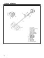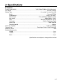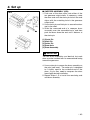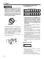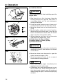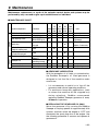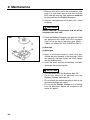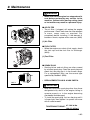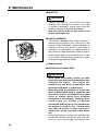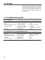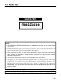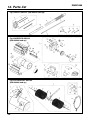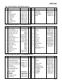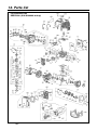
1
RMS9-99102 (501) OWNER / OPERATOR MANUAL SWEEPER RMSZ2500 WARNING WARNING The engine exhaust from this product contains chemicals known to the State of California to cause cancer, birth defects or other reproductive harm. Before using our products, please read this manual carefully to understand the proper use of your unit. APPLICABLE SERIAL NUMBERS : DRIVE UNIT 900101 and up SWEEPER UNIT 000000 and up ENGINE UNIT 50100000 and up SAFETY FIRST Instructions contained in warnings within this manual marked with a symbol concern critical points which must be taken into consideration to prevent possible serious bodily injury, and for this reason you are requested to read all such instructions carefully and follow them without fail. ■ WARNINGS IN THE MANUAL WARNING This mark indicates instructions which must be followed in order to prevent accidents which could lead to serious bodily injury or death. IMPORTANT This mark indicates instructions which must be followed, or it leads to mechanical failure, breakdown, or damage. NOTE This mark indicates hints or directions useful in the use of the product. 1. 2. 3. 4. 5. 6. 7. 8. 9. 10. 11. 12. CONTENTS Parts location …………………………………4 Specifications …………………………………5 Warning labels on the machine ……………6 Symbols on the machine ……………………7 For safe operation ……………………………8 Set up …………………………………………14 Fuel……………………………………………16 Operation ……………………………………18 Maintenance …………………………………23 Storage ………………………………………28 Troubleshooting guide ………………………28 Parts list ………………………………………29 1. Parts location 1. 2. 3. 4. 5. 6. 7. 8. 9. 10. 11. 12. 13. 14. 15. 4 Loop Handle Shoulder Strap Hanger Ignition Switch Throttle Cable Throttle Lever Throttle set Button Drive shaft Housing Drum Ass’y Sweeper Belt Spark Arrester Starter Knob Fuel Tank Primer Pump Choke Lever Air Cleaner Cover 2. Specifications ■ RMSZ2500 Overall Size(LxWxH) ························································ 70.5(1790)x27(686)x12.2(310) in(mm) Dry Weight ·········································································································· 19.8 lbs (8.91kg) Engine Type ····················································································· Air-cooled 2-stroke Gasoline Model········································································································ Zenoah GZ25N Displacement ······················································································· 1.6cu-in (25.4cm3) Max. Output ·································································· 1.2Hp (0.9kW)at 7500/min-1(rpm) Idle Speed ·························································································3000±200/min-1(rpm) Fuel ······················································································ Mixture (Gasoline 50 : Oil 1) Carburetor ·················································································· Walbro Diaphragm Type Spark Plug ····································································································NGK CMR7A Durability period ······································································································300hrs Fuel Tank Capacity·····························································································22.0 fl.oz (0.65 ) Transmission ········································································· Centrifugal Clutch, Rigid Driveshaft Reduction Ratio ······················································································································ 40.0 Standard Accessories Goggle ······················································································································· 1 pc. Tool Kit ······················································································································ 1 pc. Mask ···························································································································1 pc. Specifications are subject to change without notice. 5 3. Warning labels on the machine (1) Read owner's manual before operating this machine. (2) Wear head, eye and ear protection. (3) Warning/Attention (4) Keep all children, bystanders and helpers 15 meters away from the unit IMPORTANT If warning label peel off or become soiled and impossible to read, you should contact the dealer from which you purchased the product to order new labels and affix them in the required location(s). WARNING Never modify your machine. We won't warrant the machine, if you use the remodeled sweeper or you don't observe the proper usage written in the manual. 6 (1) Lire le mode d’emploi avant d’utiliser cette machine. (2) Porter un casque de sécurité, des lunettes de sécurité et un casque antibruit. (3) Avertissement/Attention (4) Interdire aux enfants ou à toute personne de s’approcher dans un rayon de 15 mètres de la débroussailleuse. IMPORTANT Si les étiquettes d’avertissement se décollent, deviennent sales ou impossible à lire, commander de nouvelles étiquettes auprès du revendeur pour les remplacer. AVERTISSEMENT Ne pas modifier la machine. La garantie sera annulée si la machine a été modifiée ou utilisée de manière non conforme aux instructions de ce mode d’emploi. 4. Symbols on the machine For safe operation and maintenance, symbols are carved in relief on the machine. According to these indications, please be careful not to take a mistake. (a) The port to refuel the "MIX GASOLINE" Position: FUEL TANK CAP (b) The direction to close the choke Position: AIR CLEANER COVER (c) The direction to open the choke Position: AIR CLEANER COVER IMPORTANT ENGINE INFORMATION THIS ENGINE CONFORMS TO 2005 U.S. EPA REGULATIONS FOR SMALL NONROAD ENGINES. COMPLIANCE PERIOD : CATEGORY A ENGINE FAMILY : 5KZXS.0254QR ; EM ENGINE DISPLACEMENT : 25cc REFER TO OWNER’S MANUAL FOR MAINTENANCE SPECIFICATIONS AND ADJUSTMENTS. MANUFACTURED : INFORMATION IMPORTANTE CONCERNANT LE MOTEUR CE MOTEUR EST CONFORME A LA REGLEMENTATION U.S. EPA 2005 POUR LES PETITS MOTEURS HORS-ROUTE. DUREE DE CONFORMITE : CATEGORIE A TYPE DE MOTEUR : 5KZXS.0254QR ; EM CYLINDREE DU MOTEUR : 25 cc SE REFERER AU MANUEL DE L’UTILISATEUR POUR LES SPECIFICATIONS D’ENTRETIEN ET LES REGLAGES. FABRIQUE PAR : 7 5. For safe operation 1. Read this manual carefully until you completely understand and follow all safety and operating instructions. 2. Keep this manual handy so that you may refer to it later whenever any questions arise. Also note, if you have any questions which cannot be answered herein, contact the dealer from whom you purchased the product. 3. Always be sure to include this manual when selling, lending, or otherwise transferring the ownership of this product. 4. Never allow children or anyone unable to fully understand the directions given in the manual to use the machine. ■ WORKING CONDITION 1. When using the product, you should wear proper clothing and protective equipment. (1) Helmet (2) Ear protectors (3) Protection goggles or face protector (4) Thick work gloves (5) Non-slip-sole work boots 2. And you should carry with you. (1) Attached tools and files (2) Properly reserved fuel (3) Spare blade (4) Things to notify your working area (rope, warning signs) (5) Whistle (for collaboration or emergency) (6) Hatchet or saw (for removal of obstacles) 3. Do not wear loose clothing, jewelry, short trousers, sandals, or go barefoot. Do not wear anything which might be caught by a moving part of the unit. Secure hair so it is above shoulder length. ■ WORKING CIRCUMSTANCE 1. Never start the engine inside a closed room or building. Exhaust gases contain dangerous carbon monoxide. 2. Never use the product, a. when the ground is slippery or when you can’t maintain a steady posture. 8 5. For safe operation b. At night, at times of heavy fog, or at any other times when your field of vision might be limited and it would be difficult to gain a clear view of the working area. c. During rain storms, during lightning storms, at times of strong or gale-force winds, or at any other times when weather conditions might make it unsafe to use the product. ■ WORKING PLAN 1. You should never use the product when under the influence of alcohol, when suffering from exhaustion or lack of sleep, when suffering from drowsiness as a result of having taken cold medicine or at any other time when a possibility exists that your judgment might be impaired or that you might not be able to operate the product properly and in a safe manner. 2. When planning your work schedule, allow plenty of time to rest. Limit the amount of time over which the product is to be used continuously to somewhere around 30~40 minutes per session, and take 10~20 minutes of rest between work sessions. Also try to keep the total amount of work performed in a single day under 2 hours or less. WARNING 1. If you don’t observe the working time, or working manner (See ■ USING THE PRODUCT), Repetitive Stress Injury(RSI) could occur. If you feel discomfort, redness and swelling of your fingers or any other part of your body, see a doctor before getting worse. 2. To avoid noise complaints, in general, operate product between 8a.m. and 5p.m. on weekdays and 9a.m. to 5p.m. weekends. NOTE Check and follow the local regulations as to sound level and hours of operations for the product. 9 5. For safe operation ■ BEFORE STARTING THE ENGINE 1. The area within a perimeter of 50 feet (15m) of the person using the product should be considered a hazardous area into which no one should enter. If necessary yellow warning rope, warning signs should be placed around the perimeter of the area. When work is to be performed simultaneously by two or more persons, care should also be taken to constantly look around or otherwise check for the presence and locations of other people working so as to maintain a distance between each person sufficient to ensure safety. 2. Check the condition of working area to avoid any accident by hitting hidden obstacles such as stumps, stones, cans, or broken grass. IMPORTANT Remove any obstacle before beginning work. 3. Inspect the entire unit for loose fasteners and fuel leakage. Make sure that the cutting attachment is properly installed and securely fastened. ■ STARTING THE ENGINE 1. Keep bystanders and animals at least 50feet (15m) away from the operating point. If you are approached, immediately stop the engine. 2. The product is equipped with a centrifugal clutch mechanism, so the cutting attachment begins to rotate as soon as the engine is started by putting the throttle into the start position. When starting the engine, place the product onto the ground in a flat clear area and hold it firmly in place so as to ensure that neither the cutting part nor the throttle come into contact with any obstacle when the engine starts. 10 5. For safe operation WARNING Never place the throttle into the high speed position when starting the engine. 3. After starting the engine, check to make sure that the Drum Ass’y stops rotating when the throttle is moved fully back to its original position. If it continues to rotate even after the throttle has been moved fully back, turn off the engine and take the unit to your authorized Red Max servicing dealer for repair. ■ USING THE PRODUCT IMPORTANT Use only for tasks explained in the manual. 1. Grip the handles firmly with both hands using your whole hand. Place your feet slightly apart (slightly further apart than the width of your shoulders) so that your weight is distributed evenly across both legs, and always be sure to maintain a steady, even posture while working. 2. Keep sweeping attachment below waist level. 3. Maintain the speed of the engine at the level required to perform sweeping work, and never raise the speed of the engine above the level necessary. 4. If the unit start to shake or vibrate, turn off the engine and check the whole unit. Do not use it until the trouble has been properly corrected. 5. Keep all parts of your body away from rotating sweeping attachment and hot surfaces. 6. Never touch the muffler, spark plug, or other metallic parts of the engine while the engine is in operation or immediately after shutting down the engine. Doing so could result in serious burns or electrical shock. 11 5. For safe operation • IF SOMEONE COMES 1. Guard against hazardous situations at all times. Warn adults to keep pets and children away from the area. Be careful if you are approached. Injury may result from flying debris. 2. If someone calls out or otherwise interrupts you while working, always be sure to turn off the engine before turning around. ■ MAINTENANCE 1. In order to maintain your product in proper working order, perform the maintenance and checking operations described in the manual at regular intervals. 2. Always be sure to turn off the engine before performing any maintenance or checking procedures. WARNING The metallic parts reach high temperatures immediately after stopping the engine. 3. When replacing the sweeping attachment or any other part, or when replacing the oil or any lubricant, always be sure to use only RedMax products or products which have been certified by RedMax for use with the RedMax product. 4. In the event that any part must be replaced or any maintenance or repair work not described in this manual must be performed, please contact a representative from the store nearest RedMax authorized servicing dealer for assistance. 5. Do not use any accessory or attachment other than those bearing the RedMax mark and recommended for the unit. 6. Under no circumstances should you ever take apart the product or alter it in any way. Doing so might result in the product becoming damaged during operation or the product becoming unable to operate properly. ■ HANDLING FUEL 1. The engine of the RedMax product is designed to run on a mixed fuel which contains highly flammable gasoline. Never store cans of fuel or 12 5. For safe operation refill the tank of the unit in any place where there is a boiler, stove, wood fire, electrical sparks, welding sparks, or any other source of heat or fire which might ignite the fuel. 2. Never smoke while operating the unit or refilling its fuel tank. 3. When refilling the tank, always turn off the engine and allow it to cool down. Take a careful look around to make sure that there are no sparks or open flames anywhere nearby before refueling. 4. Wipe spilled fuel completely using a dry rag if any fuel spillage occurs during refueling. 5. After refueling, screw the fuel cap back tightly onto the fuel tank and then carry the unit to a spot 10 feet (3 m) or more away from where it was refueled before turning on the engine. ■ TRANSPORTATION 1. Never transport the product over rough roads over long distances by vehicle without removing all fuel from the fuel tank. If doing so, fuel might leak from the tank during transport. 13 6. Set up SE1 ■ MOUNTING ENGINE (SE1) 1. Push the driveshaft housing toward the clutch housing and rotate it by hand to check that the driveshaft is engaged with the gears. 2. Insert the driveshaft housing into the clutch housing until it bottoms, and align the positioning holes on the clutch housing and the shaft tube and install the screw. When difficult to engage, twist the engine slightly. 3. Fasten the clamp securely with two screws. SE2 IMPORTANT Tighten the screws gradually by turns. ■ CONNECTING THROTTLE WIRE 1. Remove the air cleaner cover. 2. Connect the end of the throttle wire to the joint on the top of the carburetor. (SE2) ■ CONNECTING SWITCH WIRES • Connect the switch wires between the engine and the main unit. Pair the wires of the same color. SE3 ■ INSTALL THE HANDLE 1. Remove both screws from the handle. 2. While spreading the handle at the mounting hole, position the handle on the outer tube as shown. 3. Reinstall the two mounting screws in the handle, but do not tighten them at this time. NOTE One side of the handle is recessed to receive the hex nuts. 4. Locate the handle at the best position for operator comfort (usually about 10inches (25cm) ahead of the throttle lever), and secure it by tightening the knob at the handle base. 14 6. Set up SE4 ■ SWEEPER ASSEMBLY (SE4) 1. Push one of the drum axles onto either of the two gearcase output shafts. If necessary, rotate the drum axle until the clevis pin hole in the axle aligns with the matching hole in the gearcase output shaft. 2. Use a clevis pin and hitch pin to secure the drum axel to the shaft. 3. Slide the recessed end of a sweeper drum assembly over the assembled axle, and then push the drum down the axel until it bottoms at the clevis pin. (1) Clevis Pin (2) Hitch Pin (3) Cotter Pin (4) Drum Axle (5) Drum Assembly IMPORTANT The two drum assemblies are identical, but each drum must be installed with its recessed end facing toward the gearcase. 4. Use a cotter pin to secure the drum assembly on the axle (see inset) . The cotter pin is designed to fit tightly against the outboard end of the drum, so you may need to compress the drum face slightly during installation. 5. Repeat Steps 1-4 to install the remaining axle and drum assembly. 15 7. Fuel WARNING • Gasoline is very flammable. Avoid smoking or bringing any flame or sparks near fuel. Make sure to stop the engine and allow it cool before refueling the unit. Select outdoor bare ground for fueling and move at least 3m (10ft) away from the fueling point before starting the engine. • The RedMax engines are lubricated by oil specially formulated for air-cooled 2-cycle gasoline engine use. If RedMax oil is not available, use an anti-oxidant added quality oil expressly labeled for air-cooled 2-cycle engine use. (JASO FC GRADE OIL or ISO EGC GRADE) • Do not use BIA or TCW (2-stroke watercooling type) mixed oil. ■ RECOMMENDED MIXING RATIO GASOLINE 50:OIL 1 50:1 MIXING CHART GASOLINE gal. 1 2 3 4 5 2-CYCLE OIL fl.oz 2.6 5.2 7.8 10.4 13 GASOLINE liter 2-CYCLE OIL ml 1 20 2 40 3 60 4 80 5 100 • Exhaust emission are controlled by the fundamental engine parameters and components(eq., carburation, ignition timing and port timing) without addition of any major hardware or the introduction of an inert material during combustion. • These engines are certified to operate on unleaded gasoline. • Make sure to use gasoline with a minimum octane number of 89 RON (USA/Canada: 87AL) • If you use a gasoline of a lower octane value than prescribed, there is a danger that the engine temperature may rise and an engine problem such as piston seizing may consequently occur. • Unleaded gasoline is recommended to reduce the contamination of the air for the sake of your health and the environment. • Poor quality gasolines or oils may damage sealing rings, fuel lines or fuel tank of the engine. ■ HOW TO MIX FUEL IMPORTANT Pay attention to agitation. 1. Measure out the quantities of gasoline and oil to be mixed. 2. Put some of the gasoline into a clean, approved fuel container. 3. Pour in all of the oil and agitate well. 4. Pour In the rest of gasoline and agitate 16 7. Fuel again for at least one minute. As some oils may be difficult to agitate depending on oil ingredients, sufficient agitation is necessary for the engine to last long. Be careful that, if the agitation is insufficient, there is an increased danger of early piston seizing due to abnormally lean mixture. 5. Put a clear indication on the outside of the container to avoid mixing up with gasoline or other containers. 6. Indicate the contents on outside of container for easy identification. ■ FUELING THE UNIT 1. Untwist and remove the fuel cap. Rest the cap on a dustless place. 2. Put fuel into the fuel tank to 80% of the full capacity. 3. Fasten the fuel cap securely and wipe up any fuel spillage around the unit. 5. In the case of storing the product for a long period of time, clean the fuel tank after rendering it empty. Next, activate the engine and empty the carburetor of the composite fuel. 6. In the case of scrapping the used mixed oil container, scrap it only at an authorized repository site. NOTE As lot details of quality assurance, read the description in the section Limited Warranty carefully. Moreover, normal wear and change in product with no functional influence are not covered by the warranty. Also, be careful that, if the usage in the instruction manual is not observed as to the mixed gasoline, etc. described therein, it may not be covered by the warranty. WARNING 1. Select bare ground for fueling. 2. Move at least 10feet (3meters) away from the fueling point before starting the engine. 3. Stop the engine before refueling the unit. At that time, be sure to sufficiently agitate the mixed gasoline in the container. FOR YOUR ENGINE LIFE, AVOID; 1. FUEL WITH NO OIL(RAW GASOLINE) – It will cause severe damage to the internal engine parts very quickly. 2. GASOHOL – It can cause deterioration of rubber and/or plastic parts and disruption of engine lubrication. 3. OIL FOR 4-CYCLE ENGINE USE – It can cause spark plug fouling, exhaust port blocking, or piston ring sticking. 4. Mixed fuels which have been left unused for a period of one month or more may clog the carburetor and result in the engine failing to operate properly. 17 8. Operation ■ STARTING ENGINE OP1 WARNING The cutting head will start rotating upon the engine starts. OP2 (1) (2) (3) OP3 (5) (6) (4) 1. Rest the unit on a flat, firm place. Keep the cutting head off the ground and clear of surrounding objects as it will start rotating upon starting of the engine. 2. Push the primer pump several times until overflown fuel flows out in the clear tube. (OP1) 3. Move the choke lever to the closed position. (OP2) 4. Set the ignition switch to the “start” position. While pulling the throttle lever, push the set button, and release the throttle, then the throttle lever is in to the “start” position. (OP3) 5. While holding the unit firmly, pull out the starter rope quickly until engine fires. (OP4) (1) Choke lever (2) Close (3) Open (4) Ignition Switch (5) Start (6) Stop (7) Throttle Set Button IMPORTANT (7) OP4 • Avoid pulling the rope to its end or returning it by releasing the knob. Such actions can cause starter failures. 6. Move the choke lever downward to open the choke. And restart engine. (OP2) 7. Allow the engine to warm up for a several minutes before starting operation. NOTE 1. When restarting the engine immediately after stopping it, leave the choke open. 2. Overchoking can make the engine hard to start due to excess fuel. When the engine failed to start after several attempts, open the choke and repeat pulling the rope, or remove the spark plug and dry it. 18 8. Operation ■ STOPPING ENGINE (OP3) 1. Release the throttle lever and run the engine for a half minute. 2. Shift the ignition switch to the STOP position. IMPORTANT OP5 • Except for an emergency, avoid stopping the engine while pulling the throttle lever. .04 in (1~2mm) (1) OP6 (1) ■ ADJUSTING THROTTLE CABLE • The normal play is 1 or 2mm when measured at the carburetor side end. Readjust with the cable adjuster as required. (OP5) (1) Cable Adjuster ■ ADJUSTING IDLING SPEED (OP6) 1. When the engine tends stop frequently at idling mode, turn the adjusting screw clockwise. 2. When the cutting head keeps rotating after releasing the trigger, turn the adjusting screw counter-clockwise. (1) Idle Adjusting Screw NOTE • Warm up the engine before adjusting the idling speed. ■ BREAK-IN OPERATION OP7 The Properly Dressed Operator (OP7) (1) ALWAYS wear hearing protective devices. (2) ALWAYS wear eye protection such as goggles or safety glasses. (3) ALWAYS wear a mask to protect against dust or other airborne particles. (4) ALWAYS wear close fitting clothes. Gloves offer added protection and are strongly recommended. Do not wear clothing or jewelry that could get caught in machinery. (5) ALWAYS wear leather or heavy-rubber shoes. NEVER work barefooted! (6) BEWARE of thrown debris! (7) DIRECTION OF ROTATION 19 8. Operation • The RedMax Sweeper works best when its rubber fins can quickly slide or "skim" over the surface being swept. • New or replacement sweeper belts tend to grip or drag on hard surfaces, and should be thoroughly broken in or "scuffed" before the broom is actually put to work. • Break-in is easily accomplished by operating the RedMax Sweeper at full throttle for 3 to 5 minutes in loose gravel or similar abrasive material. Once broken in, a RedMax Sweeper will effortlessly move an amazing variety of materials, ranging from snow or standing water to heavier objects such as wood chips or gravel. • Experience will help you understand the operating principles of the RedMax Sweeper, but safe operation must be practiced from the start. OP8 ■ OPERATING TECHNIQUES (OP8)(OP9)(OP10) Operate the RedMax Sweeper at or near full throttle with its sweeper fins resting on the work surface. NOTE • It is both tiring and unnecessary to lift or hold the fins from the work surface during sweeping. OP9 • When sweeping narrow areas such as sidewalks, the RedMax Sweeper can be used to throw material directly ahead of the operator. Clearing wider areas may require sweeping at an angle to create windrows to one side of the path being cleared. • Windrows of lighter materials often can be combined into one main row or pile for eventual pickup, while heavy or bulky material may need to be collected row-by-row. • To pull debris from corners, reverse sweeper drum rotation by turning the powerhead over (throttle facing "up") . • Sweeping corners with the RedMax Sweeper upside down. (OP9) (1) Direction of rotation 20 8. Operation OP10 • For long-term inverted operation, loosen the adjustment knob to reverse the handle. (OP10) (1) Adjustment Knob WARNING Reversing the RedMax Sweeper will cause debris to be thrown back toward the operator. When reversing the RedMax Sweeper, use lower throttle settings and beware that thrown debris may also affect your footing! ■ OPERATING AND SAFETY TIPS (OP11) OP11 WARNING Maintain a shallow angle to the work surface! • A high angle of operation tends to propel the broom toward you, risking loss of control of the machine. (1) Maintain a shallow working angle. (2) A steep working angle risks loss of control! The sweeper belts may rotate when the RedMax Sweeper is started! • Always maintain a firm grip when starting the RedMax Sweeper. Beware of objects that could become entangled in or be thrown by the rotating sweeper belts. YOU MUST ALWAYS GUARD AGAINST THROWN DEBRIS! • Although the RedMax Sweeper’s sweeper belts are less forceful than a lawnmower blade, you must avoid any operation where thrown objects could pose a threat to persons or property! Never operate the RedMax Sweeper if any protective devices (engine covers, stop switch, etc.) are missing or damaged! Never operate the engine at high rpms without 21 8. Operation a load! • Doing so could damage the engine. Avoid low rpm operation • Continuous low-rpm operation can lead to premature clutch failure. ■ GENERAL SAFETY INSTRUCTIONS Work Safely The operator or bystanders can be injured if the RedMax Sweeper is misused or abused. Never allow a person without training or instruction to operate your machine. WARNING Never make unauthorized attachment installations. Stay Alert You must be physically and mentally fit to operate this machine safely. 22 9. Maintenance Maintenance, replacement, or repair of the emission control device and systems may be performed by any non-road engine repair establishment or individual. SHAFT ENGINE ■ MAINTENANCE CHART every every every every 25 40 50 100 system/compornent procedure before hours hours hours hours note use after after after after fuel leaks, fuel spillage wipe out ✔ fuel tank, air filter, fuel filter inspect/clean ✔ ✔ replace, if necessary see ■ADJUSTING replace carburetor idle adjusting screw ✔ IDLING SPEED (p.19) if necessary clean and readjust GAP: .025in(0.6~0.7mm) spark plug ✔ plug gap replace, if necessary cylinder fins, clean ✔ intake air cooling vent muffler, spark arrester, clean ✔ cylinder exhaust port throttle lever, ignition switch check operation ✔ replace if sweeper unit ✔ something's wrong gear case oil ✔ ✔ screws/nuts/bolts tighten/replace ✔ ✔ not adjusting screws ■ GEARCASE LUBRICATION With the exception of oil leaks or contamination, the RedMax Sweeper's oil filled gearcase is designed to last the life of the machine under normal use: • It is not necessary to add oil or to "top off" the gearcase under normal operating conditions. • For continuous heavy-duty applications, (such as where the machine will be stopped only during refueling), RedMax recommends replacing RedMax Sweeper gearcase oil every 40 hours of operation. ■ REPLACING THE GEARCASE OIL (MA1) Warm the gearcase oil by running the RedMax Sweeper at varying speeds for approximately 8-10 minutes, and then switch the engine to "OFF" and disconnect the spark plug wire at the engine. Use the following procedure to remove and replace all gearcase oil. 23 9. Maintenance 1. Remove the drum and axle assemblies (see page 13), and then remove the four end cap bolts and the end cap (the gearcase need not be removed from the RedMax Sweeper). 2. Allow all used gearcase oil to drain into a small container. WARNING BURN DANGER! The gearcase and oil will be extremely hot after use! MA1 3. Place the RedMax Sweeper main gear flat. Refill the gearcase with Mobil SHC 634 Synthetic Gear Oil to the top of the main gear (60ml – 1.80zs), as shown. DO NOT OVERFILL! (MA1) (1) End cap (2) Main gear 4. Apply a continuous bead of loctite ultra grey around the pilot diameter of the end cap. Install the end cap, and then install and firmly tighten the four end cap bolts. 5. Install the drum and axle assemblies, and then reconnect the spark plug wire. IMPORTANT • Use only Mobil SHC 634 Synthetic Gear Oil. • Do not mix other oils ar additives with the RedMax Sweeper Gearcase Oil. • Do not disturb the sealed end plug or bolt on the gearcase (leakage may occur). • Do not use the RedMax Sweeper if oil is leaking from the gearcase. Return the machine to the dealer for repairs. 24 9. Maintenance WARNING • Make sure that the engine has stopped and is cool before performing any service to the machine. Contact with moving cutting head or hot muffler may result in a personal injury. MA2 ■ AIR FILTER • The air filter, if clogged, will reduce the engine performance. Check and clean the filter element in warm, soapy water as required. Dry completely before installing. If the element is broken or shrunk, replace with a new one. (MA2) (1) (1) Air Filter ■ FUEL FILTER • When the engine runs short of fuel supply, check the fuel cap and the fuel filter for blockage. (MA3) MA3 (1) Fuel Filter (1) MA4 ■ SPARK PLUG • Starting failure and mis-firing are often caused by a fouled spark plug. Clean the spark plug and check that the plug gap is in the correct range. For a replacement plug, use the correct type specified by RedMax. (MA4) • REPLACEMENT PLUG IS A NGK CMR7A. .025 in 0.655mm IMPORTANT • Note that using any spark plug other than those designated may result in the engine failing to operate properly or in the engine becoming overheated and damaged. • To install the spark plug, first turn the plug until it is finger tight, then tighten it a quarter turn more with a socket wrench. TIGHTENING TORQUE: 87~104 in-lbs (9.8~11.8 N.m.) 25 9. Maintenance ■ MUFFLER WARNING • Inspect periodically, the muffler for loose fasteners, any damage or corrosion. If any sign of exhaust leakage is found, stop using the machine and have it repaired immediately. • Note that failing to do so may result in the engine catching on fire. MA5 (1) ■ SPARK ARRESTER • The muffler is equipped with a spark arrester to prevent red hot carbon from flying out of the exhaust outlet. Periodically inspect and clean as necessary with a wire brush. In the State of California it is required by law (Section 4442 of the California Public Resources Code) to equip a spark arrester when a gas powered tool is used in any forest covered, brush covered, or grass covered unimproved land. (MA5) (1) Spark Arrester ■ INTAKE AIR COOLING VENT WARNING • Never touch the cylinder, muffler, or spark plugs with your bare hands immediately after stopping the engine. The engine can become very hot when in operation, and doing so could result in severe burns. • When checking the machine to make sure that it is okay before using it, check the area around the muffler and remove any wood chips or leaves which have attached themselves to the sweeper. Failing to do so could cause the muffler to become overheated, and that this in turn could cause the engine to catch on fire. Always make sure that the muffler is clean and free of wood chips, leaves, and other waste before use. • Check the intake air cooling vent and the area around the cylinder cooling fins after every 25 hours of use for blockage, and remove any 26 9. Maintenance MA6 (1) waste which has attached itself to the sweeper. Note that it is necessary to remove the engine cover shown in (MA6) in order to be able to view the upper part of the cylinder. IMPORTANT (2) • If waste gets stuck and causes blockage around the intake air cooling vent or between the cylinder fins, it may cause the engine to overheat, and that in turn may cause mechanical failure on the part of the sweeper. (MA6) (1) Cylinder (2) Intake Air Cooling Vent (back) MA7 ■ PROCEDURES TO BE PERFORMED AFTER EVERY 100 HOURS OF USE 1. Remove the muffler, insert a screwdriver into the vent, and wipe away any carbon buildup. Wipe away any carbon buildup on the muffler exhaust vent and cylinder exhaust port at the same time. 2. Tighten all screws, bolts, and fittings. 3. Check to see if any oil or grease has worked its way in between the clutch lining and drum, and if it has wipe it away using oil-free, lead-free gasoline. 27 10. Storage • Aged fuel is one of major causes of engine starting failure. Before storing the unit, empty the fuel tank and run the engine until it uses all the fuel left in the fuel line and the carburetor. Store the unit indoor taking necessary measures for rust prevention. 11. Troubleshooting guide Case 1. Starting failure CHECK fuel tank fuel filter carburetor adjustment screw sparking (no spark) spark plug ➞ ➞ ➞ ➞ ➞ ➞ PROBABLE CAUSES incorrect fuel fuel filter is clogged out of normal range spark plug is fouled/wet plug gap is incorrect disconnected ➞ ➞ ➞ ➞ ➞ ➞ ACTION drain it and with correct fuel clean adjust to normal range clean/dry correct (GAP: 0.6~0.7mm) retighten Case 2. Engine starts but does not keep running/Hard re-starting. CHECK fuel tank carburetor adjustment screw muffler,cylinder (exhaust port) air cleaner cylinder fin, fan cover ➞ ➞ ➞ ➞ ➞ PROBABLE CAUSES incorrect fuel or staled fuel out of normal range carbon is built-up clogged with dust clogged with dust ➞ ➞ ➞ ➞ ➞ ACTION drain it and with correct fuel adjust to normal range wipe away wash clean When your unit seems to need further service, please consult with our RedMax service shop in your area. 28 12. Parts list SWEEPER RMSZ2500 NOTE : 1. Use KOMATSU ZENOAH genuine parts as specified in the parts list for repair and/or replacement. 2. KOMATSU ZENOAH does not warrant the machines, which have been damaged by the use of any parts other than those specified by the company. 3. When placing parts orders for repair and/or replacement, check if the model name and the serial number are applicable to those specified in the parts list, then use parts number described in the parts list. 4. The contents described in the parts list may change due to improvement. 5. The parts for the machine shall be supplied seven (7) years after the machine is discontinued. [It is possible that some specific parts may be subject to change of their delivery term and list price within the limit of seven (7) years after the machine is discontinued. It is also possible that some parts may be available even after the limit of seven (7) years.] APPLICABLE SERIAL NUMBERS : DRIVE UNIT 900101 and up SWEEPER UNIT 000000 and up Mar.2000 ENGINE UNIT 50100000 and up 29 12. Parts list Fig.1 SHAFT GROUP (S/N 900101 and up) Fig.2 SWEEPER GROUP (S/N 000000 and up) Fig.3 ACCESSORY GROUP (S/N 000000 and up) 30 RMSZ2500 RMSZ2500 Fig.1 SHAFT GROUP (S/N 900101 and up) Key# 1 2 3 4 5 6 7 8 9 10 Description PIPE COMP. SHAFT GRIP LEVER COMP. • CORD (A) • CORD (B) • TUBE • CABLE PLATE-NAME PLATE Part Number Q'ty Key# T3074-12110 3074-12210 3577-32141 T3002-12200 T3002-12220 T3002-12230 T3002-12240 T3002-83100 RMS9-99001 6425-12552 1 1 1 1 1 1 1 1 1 1 11 12 13 14 15 Description TOOL-SET • SOCKET • WRENCH • SPANNER • BAR Part Number Q'ty T3002-91000 T3002-91310 09007-00425 3540-91120 3540-91110 1 1 1 1 1 Part Number Q'ty 02180-10605 72030-14120 72030-14130 99909-33005 99909-33004 99909-33007 61739 99909-33116 99909-33020 99909-33008 99909-33118 99909-33034 72959-13330 99909-6771 2 1 2 2 4 12 2 2 2 2 2 1 1 1 Part Number Q'ty 99909-22023 99909-22024 99909-22025 99909-22026 99909-33022 T3002-17200 6420-17300 6420-17400 9366-17110 9366-17120 6420-17410 0263-90525 1 2 2 2 1 1 1 1 1 1 1 1 Fig.2 SWEEPER GROUP (S/N 000000 and up) Key# Description Part Number Q'ty Key# 1 2 3 4 5 6 7 8 9 10 11 12 13 14 15 16 17 18 Gear Case • Bolt M6x30 • Spring Washer M6 • Washer M6, t1.6 • Washer M6, t1.6 • Nut M6 • Bolt M5x12 • Spring Washer M5 • Washer M5 • Washer M5 • Spring Washer M5 • Bolt M5x8 • Plug, Housing • Oil Seal • Oil Seal • Bolt #10-25 5/8 Handle Assy • Scraw 99909-33031 01252-30630 01601-20619 50509 50509 01580-10605 01252-30512 01601-20513 01641-2058 01641-2058 01601-20513 80008 50502 50514 50515 50508 72951-14100 72030-14141 1 1 1 1 1 1 1 1 1 1 1 1 1 1 2 4 1 1 19 20 21 22 23 24 25 26 27 28 29 30 31 32 Description • Nut • Knob • Washer Belt Drum Belt Clip Decal Drum Axle Cotter Pin Hitch Pin Clevis Pin Tube Protector Spacer Safety Kit Ear Plugs, Dust Musk& Eye Protection Fig.3 ACCESSORY GROUP (S/N 000000 and up) Key# Description Part Number Q'ty Key# 99909-11001 1 99909-11004 1 • Gear Shaft Adapter, LH 99909-11112 • Gear Shaft Adapter, RH 99909-11113 • End Cap 99909-11114 • Hardware Kit 99909-311 1 1 2 1 12 13 14 15 16 17 18 19 20 21 22 23 1 Brush Sweeping Att. Including Safety Kit (Fig.2 Key#32) 2 • Nylon Brush Ass’y Contents a pair of burush 3 4 5 6 Roll Pinx2, Flat Washerx2 Bolt RH (Black)x1 and Bolt LH (Silver)x1 7 8 9 10 11 Debris Shield • Boltspw • Spacer • Handle bracket • Lowercap 99909-33021 11022-05250 22036-14130 72051-14110 72051-14120 1 4 1 1 1 Description • Shield bracket • Bolt • Washer • Nut • Debris shield Strap Assy HANGER-ASSY • HANGER-COMP • • HANGER • • CLAMP • • SLEEVE • SCREW 31 12. Parts list Fig.4 ENGINE UNIT RMSZ2500 (S/N 50100000 and up) 32 Fig.4 ENGINE UNIT RMSZ2500 (S/N 50100000 and up) Key# 1 2 3 4 5 6 7 8 9 10 11 12 13 14 15 16 17 18 19 20 21 22 23 24 25 26 27 28 29 30 31 32 33 34 35 36 37 38 39 40 41 42 43 44 45 46 47 48 49 50 51 52 53 54 55 56 57 58 59 60 61 62 63 64 65 66 67 68 69 70 71 Description CYLINDER GASKET, base BOLT INSULATOR GASKET, insulator GASKET, carburetor SCREW REEDVALVE (S) ASSY • VALVECASE (S) • REEDVALVE • STOPPER • SCREW PIRE AIR (S) REEDVALVE (F) ASSY • VALVECASE (F) • REEDVALVE • STOPPER • SCREW PIPE AIR (F) GASKET, valve SCREW CRANKCASE COMP. • PIN GASKET BEARING SEAL SEAL SNAP RING BOLT GUARD SCREW PISTON RING PIN RING BEARING WASHER CRANKSHAFT COMP. NUT KEY ROTOR COIL ASSY • CORD • CAP SPACER BOLT CARBURETOR ASSY • REBUILD KIT • • BODY ASSY • • • SCREEN • • • VALVE • • • SPRING • • • SCREW • • • PIN • • • LEVER • • GASKET KIT • • • DIAPHRAGM • • • GASKET, diaphragm • • • DIAPHRAGM, pump • • • GASKET, pump • • • RING • BODY, purge • COVER, pump • PUMP, priming • JET • O-RING • RING • SWIVEL • VALVE ASSY • SCREW • BRACKET Part Number 4810-12111 4810-12210 1850-12130 4810-13161 4810-13120 4810-13130 0263-90520 4810-16100 4810-16110 4810-16120 4810-16130 4810-16170 4810-16150 4810-16200 4810-16210 4810-16120 4810-16130 4810-16170 4810-16160 4810-16140 4810-16180 4810-21100 2629-21130 4810-21140 06030-06001 4810-21210 1850-21220 04065-02812 01252-30530 4810-22110 0263-90510 4810-41110 5910-41210 1600-41310 1260-41320 1140-41330 1101-41340 4810-42000 1650-43230 1000-43240 5501-71110 4810-71200 4810-71220 2616-71320 1260-71261 4500-72150 4810-81001 4810-06030 4810-81450 ––––––––– ––––––––– ––––––––– ––––––––– ––––––––– ––––––––– 4810-06020 ––––––––– ––––––––– ––––––––– ––––––––– 4810-81130 1850-81490 1850-81520 1751-81510 4810-81250 1751-81240 1751-81130 1881-81140 ––––––––– 1752-81110 5500-81120 Q'ty Key# 1 1 2 1 1 1 1 1 1 1 1 1 1 1 1 1 1 1 1 2 6 1 3 1 2 1 1 1 3 1 1 1 2 1 2 1 2 1 1 1 1 1 1 1 2 2 1 1 1 – – – – – – 1 – – – – 1 1 1 1 1 1 1 1 – 2 1 72 73 74 75 76 77 78 79 80 81 82 83 84 85 86 87 88 89 90 91 92 93 94 95 96 97 98 99 100 101 102 103 104 105 106 107 108 109 110 111 112 113 114 115 116 117 118 119 120 121 122 123 124 125 126 127 128 129 130 131 132 133 134 135 136 137 138 139 140 141 142 Description • NUT, adjuster • SCREW, adjuster • SCREW • WASHER SCREW MUFFLER ASSY • MUFFLER • ARRESTER BOLT GASKET COVER ASSY • COVER COMP. • • COVER, fan • • DRUM • • SNAPRING • • BEARING • • SNAP RING • BRACKET (A) • BRACKET (B) • CUSHION • BOLT • BOLT SCREW SCREW COVER, engine PLATE SCREW SHOE SPRING SCREW WASHER WASHER CAP SPRING CORD CORD, carth TUBE PLUG GROMMET RECOIL ASSY • REEL • SCREW • SPRING, spiral • COLLAR • ARM • ROPE • KNOB • PLATE, stopper PULLEY SCREW BODY ASSY • PLATE, choke • LEVER, choke • SCREW ELEMENT SCREEN COVER ASSY • KNOB TANK ASS'Y • CAP ASS'Y • • HOLDER ASSY • • PACKING • PIPE COMP. • FLTER ASSY • CLIP SCREW LABEL, recoil LABEL, cover GUARD SCREW CLIP Part Number 1751-81180 1918-81170 1850-81530 5500-81160 0263-90560 4810-15100 4810-15111 4810-15140 01252-30550 4810-15410 4810-31000 4810-31100 4810-31110 4810-31120 04065-02812 06004-06001 04064-01210 6470-31211 6470-31221 6470-31230 01252-30530 01252-30514 5500-85510 0263-90520 4810-32111 4810-12310 0263-90510 1140-51111 1600-51223 1140-51250 1140-51230 1970-51241 4810-72110 1900-72120 4810-71240 4810-71250 2850-71320 4810-73110 4810-72120 4810-75100 4500-75120 4500-75150 1850-75130 4500-75180 4500-75190 4810-75160 3330-75421 4810-75170 4500-75210 5500-85510 4810-82100 4810-82130 5500-82140 2630-33610 4810-82170 4810-82180 4810-82200 5500-82221 4810-87000 4500-85200 4500-85300 4500-85220 4810-85300 5500-85400 1260-85460 5500-85510 ––––––––– 4810-31131 4810-31911 0263-90525 1950-86120 Q'ty 1 1 4 1 2 1 1 1 2 1 1 1 1 1 1 1 1 1 1 1 2 1 1 4 1 1 2 2 1 2 2 2 1 1 1 1 1 1 1 1 1 1 1 1 1 1 1 1 1 2 1 1 1 1 1 1 1 1 1 1 1 1 1 1 1 3 – 1 1 2 1 33 RedMax LIMITED WARRANTY EMISSION-RELATED PARTS, FOR TWO (2) YEARS FROM THE DATE OF ORIGINAL DELIVERY OF THE UNIT, KOMATSU ZENOAH AMERICA INC. (THE COMPANY), THROUGH ANY RedMax DEALER, WILL REPAIR OR REPLACE, FREE OF CHARGE, FOR THE ORIGINAL AND EACH SUBSEQUENT PURCHASER, ANY PART OR PARTS FOUND TO BE DEFECTIVE IN MATERIAL AND/OR WORKMANSHIP. EMISSION-RELATED PARTS ARE: THE CARBURETOR ASSY, COIL ASSY, ROTOR, SPARKPLUG, AIR FILTER, FUEL FILTER, INTAKE MANIFOLD, AND THE GASKETS ALL OTHER PARTS EXCEPT ABOVE PARTS, FOR TWO (2) YEARS OF USE, 90 DAYS FOR RENTAL USE, FROM THE DATE OF ORIGINAL PURCHASE, THE COMPANY, THROUGH ANY RedMax DEALER, WILL REPAIR OR REPLACE, FREE OF CHARGE, FOR THE ORIGINAL PURCHASER, ANY PART OF PARTS FOUND TO BE DEFECTIVE IN MATERIAL AND/OR WORKMANSHIP. THIS IS THE EXCLUSIVE REMEDY. THE PURCHASER SHALL BEAR COSTS OF TRANSPORTING THE UNIT TO AND FROM THE RedMax DEALER. THE PURCHASER SHALL NOT BE CHARGED FOR DIAGNOSTIC LABOR WHICH LEADS TO THE DETERMINATION THAT A WARRANTED PART IS DEFECTIVE, IF THE DIAGNOSTIC WORK IS PERFORMED AT THE RedMax DEALER. THE PURCHASER OR OWNER IS RESPONSIBLE FOR THE PERFORMANCE OF THE REQUIRED MAINTENANCE AS DEFINED BY THE MANUFACTURER IN THE OWNER/OPERATOR MANUAL. ANY WARRANTED PART WHICH IS NOT SCHEDULED FOR REPLACEMENT AS REQUIRED MAINTENANCE, OR WHICH IS SCHEDULED ONLY FOR REGULAR INSPECTION TO THE EFFECT OF "REPAIR OR REPLACE AS NECESSARY" SHALL BE WARRANTED FOR THE WARRANTY PERIOD.ANY WARRANTED PART WHICH IS SCHEDULED FOR REPLACEMENT AS REQUIRED MAINTENANCE SHALL BE WARRANTED FOR THE PERIOD OF TIME UP TO THE FIRST SCHEDULED REPLACEMNET POINT FOR THE PART. ANY REPLACEMENT PART THAT IS EQUIVALENT IN PERFORMANCE AND DULABILITY MAY BE USED IN NONWARRANTY MAINTENANCE OR REPAIRS, AND SHALL NOT REDUCE THE WARRANTY OBLIGATION OF THE COMPANY. THE COMPANY IS LIABLE FOR DAMAGES TO OTHER ENGINE COMPONENTS CAUSED BY THE FAILURE OF A WARRANTED PARTS STILL UNDER WARRANTY. THE WARRANTY DOES NOT APPLY TO THOSE UNITS WHICH HAVE BEEN DAMAGED BY NEGLIGENCE OF INSTRUCTION LISTED IN THE OWNER/OPERATOR MANUAL FOR PROPER USE AND MAINTENANCE OF THE UNITS, ACCIDENTAL MISHANDLING, ALTERATION, ABUSE, IMPROPER LUBULICATION, USE OF ANY PARTS OR ACCESSARIES OTHER THAN THOSE SPECIFIED BY THE COMPANY, OR OTHER CAUSES BEYOND THE CONPANY'S CONTROL. THIS WARRANTY DOES NOT COVER THOSE PARTS REPLACED BY NORMAL WEAR OR HARMLESS CHANGES IN THEIR APPEARANCE. THERE ARE NO OTHER EXPRESS WARRANTIES. IMPLIED WARRANTIES INCLUDING THOSE OF MERCHANTABILITY AND FITNESS FOR A PARTICULAR PURPOSE ARE LIMITED TO TWO (2) YEARS OF USE FROM THE ORIGINAL DELIVERY DATE. LIABILITIES FOR INCIDENTAL OR CONSEQUENTIAL DAMAGE UNDER ANY AND ALL WARRANTIES ARE EXCLUDED. SOME STATES DO NOT ALLOW LIMITATION ON HOW LONG AN IMPLIED WARRANTY LASTS OR EXCLUSION OR LIMITATION OF INCIDENTAL OR CONSEQUENTIAL DAMAGES, SO THE ABOVE LIMINATION OR EXCLUSION MAY NOT APPLY TO YOU. THIS WARRANTY GIVES YOU SPECIFIC LEGAL RIGHTS, AND YOU MAY ALSO HAVE OTHER RIGHTS WHICH VARY FROM STATE TO STATE. IF YOU NEED TO OBTAIN INFORMATION ABOUT THE NEAREST SERVICE CENTER, PLEASE CALL KOMATSU ZENOAH AMERICA INC. AT (770)-381-5147. IMPORTANT: YOU WILL RECEIVE A WARRANTY REGISTRATION CARD AT TIME OF PURCHASE.PLEASE FILL OUT THE CARD AND SEND IT TO RedMax / KOMATSU ZENOA AMERICA WITHIN SEVEN (7) DAYS.BE SURE TO KEEP A COPY FOR YOUR RECORDS. KOMATSU ZENOAH AMERICA INC. 4344 Shackleford Road Suite 500 Norcross, Georgia 30093 RedMax Garantie limitée Pièces en rapport avec les émissions de gaz d'échappement : KOMATSU ZENOAH AMERICA INC., par l'intermédiaire de n'importe quel revendeur RedMax, réparera gratuitement ou remplacera gratuitement pour l'acheteur initial et chaque acheteur successif toute(s) pièce(s) se révélant de constitution et/ou de montage défectueux pendant deux (2) ans à compter de la date initiale de livraison d’une unité. Les pièces en rapport avec les émissions de gaz d'échappement sont: l'assemblage carburateur, l'assemblage bobine, le rotor, la bougie, le filtre à air, le filtre à carburant, la tubulure d'admission et les joints Toutes les pièces autres que celles mentionnées ci-dessus, deux (2) ans d’utilisation, 90 jours pour la location, à compter de la date d’achat initial. La société, par l’intermédiaire d’un distributeur RedMax, réparera ou remplacera toute(s) pièce(s), sans frais et au bénéfice de l’acheteur original, en prenant en charge les frais de pièces et/ou de main d’œuvre. Telles sont les limites de la garantie. Le coût du transport de l'unité jusqu'au revendeur RedMax et depuis celui-ci sera à la charge de l'acheteur. L'acheteur ne supportera pas le coût de main d'oeuvre du diagnostic qui amène à la conclusion qu'une pièce garantie est défectueuse, si ce diagnostic est effectué chez le revendeur RedMax. L’acheteur ou propriétaire a pour responsabilité d’effectuer l’entretien obligatoire tel que défini par le fabricant dans le manuel du propriétaire/de l'utilisateur. Toute pièce garantie dont le remplacement n'est pas prévu dans le cadre de l’entretien obligatoire, ou pour laquelle est seulement prévue une inspection périodique pour "remplacement ou réparation si nécessaire" sera garantie pour la période de garantie. Toute pièce garantie arrivée à l’échéance de son premier remplacement prévu sera garantie jusqu’à celui-ci. Toute pièce de rechange équivalente en performance ou en durabilité peut être utilisée pour l’entretien hors-garantie ou les réparations hors-garantie, et ce sans réduire l’obligation de garantie incombant à la société. La société sera tenue responsable des dommages aux autres composants du moteur causés par la défaillance de pièce(s) garantie(s) en période de garantie. La garantie ne s'applique pas aux unités endommagées par suite de: négligence dans la mise en oeuvre des instructions spécifiées dans le manuel du propriétaire/de l'utilisateur en vue d’une utilisation et d’un entretien correct, fausse manœuvre accidentelle, modification, utilisation abusive, lubrification incorrecte, utilisation de pièces ou d’accessoires autres que ceux spécifiés par la société, ou autres causes hors du contrôle de la société. Cette garantie ne couvre pas les pièces remplacées en raison de leur usure normale ou de changements d’apparence sans effets. Il n'existe aucune autre garantie explicite. Les garanties implicites, y compris la valeur marchande et la valeur d’usage pour une utilisation particulière, sont limitées à deux (2) ans d’utilisation à compter de la date originale de livraison. Les responsabilités pour les dommage conséquents ou incidents sont exclues de toutes les garanties. Certaines provinces n'autorisant pas les limitations à la durée des garanties implicites, ou les exclusions ou limitations relatives aux dommages incidents ou conséquents, la limitation indiquée ci-dessus peut ne pas vous être applicable. Cette garantie vous donne des droits juridiques spécifiques, et vous pouvez également jouir d’autres droits variant d'une province à l'autre. Si vous désirez obtenir des informations sur le centre de service le plus proche, veuillez appeler KOMATSU ZENOAH AMERICA INC. au (770)-381-5147 Note importante: vous recevrez une carte d'enregistrement de garantie au moment de l'achat. Veuillez la remplir et l'adresser à RedMax / KOMATSU ZENOAH AMERICA sous sept (7) jours en prenant soin de conserver une copie pour vous. KOMATSU ZENOAH AMERICA INC. 4344 Shackleford Road Suite 500 Norcross, Georgia 30093 KOMATSU ZENOAH AMERICA INC. 4344 Shackleford Road Suite 500 Norcross, Georgia 30093 © Printed in Japan