1
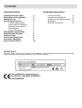
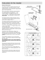
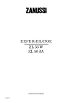
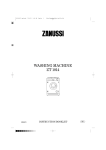
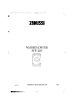
Electric Ceramic Hob
ZKF641H
Operating and Installation Instructions
User Instructions
Important hints on safety
Description of the appliance
Before first use
Operating Instructions
Ceramic glass surface
Heat Controls & Settings
Residual heat indicator
Pots and pans
Energy Saving tips
Maintenance and Cleaning
Something Not Working
Customer Care
Service and Spare Parts
Guarantee Conditions
Service Force Centres
Installation Instructions
3
4
4
5
5
5
6
6
6
7
8
8
8
9
10
Technical Details
Unpacking and Disposal
Installing in the kitchen worktop
Building-In
Electrical Connection
12
12
12
13
14
RATING PLATE
The rating plate is located on the bottom of the appliance. Once the appliance has been built-in the rating
plate is no longer visible. Please write the ‘F Nr.’ into the box below.
This appliance is corresponding to
the EG-rules 73/23/EWG, 89/336/EWG
and 90/683/EWG.
This safety information is provided in the interests of your safety. Please read it carefully
before installing or using the hob. If you are unsure if the meaning of any of the warnings
please contact our Customer Care Department.
Installation
• This appliance must be installed by a qualified
electrician / competent person, according to the
manufacturer’s instructions and to the relevant
British Standards.
• Remove all packaging before using the
appliance.
• Ensure the electrical supply complies with the
type stated on the rating plate.
• Do not attempt to modify the hob in any way.
• Do not install the hob if the ceramic glass is
damaged or cracked.
Child Safety
• This appliance is designed to be operated by
adults. Do not allow children to play near or with
the appliance.
• The appliance gets hot when it is in use.
Children should be kept away until it has cooled.
• Children can also injure themselves by pulling
pots or pans off the hob.
During Use
• Only use the hob when it is fully installed.
• This hob is intended for domestic cooking only.
It is not designed for commercial or industrial
purposes.
• Ensure the power ON/OFF switch is off when
the hob is not in use.
• When using other electrical appliances, ensure
the cable does not come into contact with the
hot surfaces of the hob.
• Do not use unstable or misshapen pans on the
hob.
• Never leave the hob unattended when cooking
with fat or oil.
• Never use plastic or aluminium foil dishes on the
hob.
Safety Hints and information
Environmental information
3
• The cooking zones heat up quickly when they
are turned on. Only turn them on when a
saucepan is on the cooking zone.
• The residual heat indicator will not operate if
there is a power failure.
• Do not store temperature sensitive or
inflammable materials (e.g. detergents or
aerosols) in drawers or cupboards underneath
the hob.
• The hob surface must not be used for storage or
as a working area.
• Do not allow sugar (solid or liquid) or plastic to
come into contact with the hob surface when
hot.
• Clean the hob in accordance with the
Maintenance and Cleaning instructions.
• Do not use the hob if the glass is damaged or
becomes cracker, contact your local Service
Force Centre.
Service
• This hob should only be repaired or serviced by
an authorised Service Engineer and always
insist on genuine spare parts.
Disposal
• Please dispose of any packaging material and
old appliances at authorised disposal sites with
due regard for the environment.
1. Cooking Zone
ø 180 mm
1800 W
2. Cooking Zone
ø 180 mm
1800 W
3. Cooking Zone
ø 145 mm
1200 W
4. Cooking Zone
ø 145 mm
1200 W
5. Residual Heat Indicator
6. Heat setting control knobs
Voltage AC 230 V
Total connected Load 6.0 kW
Please check that the appliance was
delivered in perfect condition.
Appliances with obvious transport
damage must not be connected to the
mains.
First Cleaning
In order to remove any remnants left by production,
clean the hob before it is first use.
Ensure any labels and protective films on the hob
are removed.
Clean the ceramic glass and the frame with hot
water and a little washing up liquid added.
First Heating Up
Check each cooking zone, in turn, by briefly
switching to the maximum setting (10).
When using the ceramic hob for the first time it can
temporarily emit an odour.
4
Ceramic glass surface
The cooking surface is made of proven ceramic
glass. The surface is non-porous and, in addition,
insensitive to quick variations in temperature.
Therefore pots may be moved from a hot to a cold
zone.
When switching on the cooking zones you may
hear a short-term audible buzzing sound of the
radiant elements. This will not harm the
performance of the appliance.
Keep all objects and materials that
might smelt away from the heat zones.
Sugar solutions, food stuffs with a high
sugar content, plastics, or kitchen foil –
must be removed immediately with a
glass scraper. If this type of soiling is
not removed immediately it can cause
irreparable damage to the ceramic
glass surface. Which is not covered by
the guarantee.
When the surface has cooled, wipe
over with a damp cloth and Vitroclen.
Heat Controls
Heat Zone Setting Chart
The cooking zones regulate the heating capacity of
the cooking zones.
The control knobs for the cooking zones can be
turned to the left and to the right to desired
position.
Function
1 = minimum setting
10 = maximum setting
0
= OFF
Examples
OFF
0
Keeping warm,
gentle heating,
beating or melting
1
2
Swelling, defrosting
Frying without crust
3
4
Simmering, swelling
After use make sure that the appliance is
switched off by ensuring that all control
knobs are set to ‘0’.
5
Boiling
6
Frying
7
Baking
Quick frying
8
Parboiling, lightly
frying
5
9
10
Small amounts of
hotpot, sauce,
butter or chocolate
Rice, spinach
Omelette, fried
eggs
Vegetables, fruit
with little liquid,
farinaceous
product
Potatoes, stews,
soups, sauces
Schnitzel, cutlets,
meatballs, fish
fillets in deep fat.
Potato fritters,
pancakes, fried
eggs
… the switch back
to an appropriate
setting
Residual Heat indicator
Each cooking zone is related to one indicator. The
warning lamp illuminates when the surface of the
corresponding cooking zone reaches a
temperature which could cause burns.
The indicator remains illuminated after the area
heated has been switched off as long as the
residual heat of the corresponding cooking zone
could cause burns.
The light will go out when the temperature falls
below 60°C.
Saucepans and frying pans.
Saucepans and frying pans should not be smaller
than the cooking zone, and preferably not more
that 10-15 mm larger than the cooking zone.
The bases should always be clean and dry. Cook
with a lid in place.
Always using cooking and frying utensils with
smooth, flat bottoms. Bases with burrs and sharp
edges will scratch the ceramic glass surface.
Scratches can also be caused by grains of sand
(e.g. originating from washed vegetables), drawn
over the cooking surface with the pan, or by burrs
and rims on the base of pans.
To avoid scratching or damaging the ceramic
glass surface, pots and pans should be moved
on the hob by lifting them and not by sliding.
Utensils with aluminium and copper bases can
leave behind metallic discolouration which can only
be removed with difficulty and sometimes not at all.
When cold, pan bases normally curve slightly
inwards by approx. 0.1-0.5 mm (concave). In no
case should they curve outwards (convex).
Follow any guidelines provided by the saucepan
manufacturer. Ensure that they are recommended
for use on ceramic hobs.
Energy Consumption
To save energy, you should…
• Switch off the cooking zone a few minutes
before the end of the cooking time, in order to
make use of the residual heat.
• Use the residual heat of the cooking zone for
keeping food warm, or for. melting.
• Position pots and pans centrally on the cooking
zone
• Only use cooking and frying utensils with flat
smooth bases.
• Place pots and pans in position before switching
on the cooking zone.
• Wherever possible, cover pots and pans with a
lid.
6
Before cleaning, make sure that the hob is cool and
disconnected from the power supply.
Never use aggressive or abrasive agents,
such as oven sprays, stain or rust
removers, scouring powder, or sponges
with an abrasive effect.
Special cleaning agents such as Vitroclen and
ceramic glass scrapers are available from
department stores and electrical specialists.
Cleaning after each use
• Slight, non-burnt soiling can be wiped off with a
damp cloth.
• Burnt soiling has to be removed with a scraper.
Afterwards wipe off the ceramic glass surface
with a damp cloth and Vitroclen.
Stain removal
• Light metallic stains (aluminium residues) can
be removed from the cooking zone with a
ceramic hob cleaning agent such as Vitroclen.
• Sugar solutions, food stuffs with a high sugar
content, plastics, or kitchen foil must be
removed immediately with a scraper. If this type
of soilage is not removed immediately it can
cause irreparable damage to the ceramic glass
surface. When the surface has cooled wipe
over with a damp cloth and Vitroclen.
• Before using any detergent or cleaning agent on
the ceramic glass surface, ensure they are
recommended for use on ceramic hobs.
• Do not apply any cleaning agents to hot cooking
zones. Ensure that any residues are wiped off
before the cooking zones are used again.
Special Problems
… when a chemical cleansing agent is not
Use a glass scraper to aid cleaning.
sufficient.
… when dark stains have appeared.
If cleaning with a glass scraper and Vitroclen does
not help, the décor has been cleaned with an
unsuitable cleaning agent or scoured by rough
ban bases.
… when metallic discolouration appears on the
The cleansing agents that were used were for the
cooking surface.
most part unsuitable. The discolouration can only
be removed with difficulty using Vitroclen.
… when the surface shows scratches or hollows.
These flaws are caused by scratching or melted
objects and cannot be removed, however, this
does not reduce the performance of the hob.
7
If your hob is not functioning correctly please carry
out the following checks before calling out an
engineer.
Important: If you call out an engineer to a fault
listed below, or to repair a fault caused by incorrect
use or installation, a charge will be made even if
the appliance is under guarantee.
Symptom
•
Possible Solution
•
•
•
The cooking zones do not function.
Check the mains has not failed.
Check a power level has been selected.
The cooking zone may have only been switched
on for a short while, and is therefore below
60°C.
• This is not a fault, the buzzing will disappear as
the zone heats up.
• This is probably the result of burned of remnants
that have not been removed regularly. They will not
affect the function of the hob.
• After switching off a cooking zone the residual
heat indicator is not illuminated.
• A buzzing is heard when a cooking zone is first
switched on.
• Discolouration appear in the cooking zone.
If after carrying out the above checks there is still a fault, contact your local Zanussi Service Force Centre.
In the event of your appliance requiring service, or
if you wish to purchase spare parts, please contact
your local Zanussi Service Force Centre by
telephoning:-
Customer Care
For general enquiries concerning your Zanussi
appliance or for further information on Zanussi
products, please contact our Customer Care
Department by letter or telephone at the address
below or visit our website at www.zanussi.co.uk
08705 929929
Your telephone call will be automatically routed to
the Service Force Centre covering your post code
area. The addresses are listed on the following
pages.
Before calling out an engineer, please ensure you
have read the details under the heading
“Something Not Working.”
Customer Care Department
Zanussi
55-77 High Street
Slough
Berkshire
SL1 1DZ
08705 727727 (*)
When you contact the Service Force Centre you
will need to give the following details:
* calls to this number may be recorded for training
purposes
1. Your name, address and post code
2. Your telephone number
3. Clear and concise details of the fault
4. The model and serial number of the appliance
(found on the rating plate)
5. The purchase date
8
We Zanussi undertake that if within 24 months of the date of the purchase this Zanussi appliance
or any part thereof is proved to be defective by reason only of faulty workmanship or materials,
the company will, at our option repair or replace the same FREE OF CHARGE for labour,
materials or carriage on condition that:
The appliance has been correctly installed and used only on the electrical supply stated on the
rating plate.
The appliance has been used for normal domestic purposes only, and in accordance with the
manufacturer’s instructions.
The appliance has not been serviced, maintained, repaired, taken apart or tampered with by any
person not authorised by us.
All service work under this guarantee must be undertaken by a Zanussi Service Force Centre.
Any appliance or defective part replaced shall become the Company’s property.
Home visits are made between 8.30am and 5.30pm Monday to Friday. Visits may be available
outside these hours in which case a premium will be charged.
EXCLUSIONS
This Guarantee does not cover:
Damage or calls resulting from transportation, improper use or neglect, the replacement of any
light bulbs or removable parts of glass or plastic.
Costs incurred for calls to put right an appliance improperly installed or calls to appliances
outside the United Kingdom.
Appliances found to be in use within a commercial environment, plus those which are the subject
of rental agreements.
Products of Zanussi manufacture which are not marketed by Zanussi.
This guarantee is in addition to your statutory and legal rights.
ZANUSSI EUROPEAN GUARANTEE
If you should move to another country within Europe then your guarantee moves with you to your
new home subject to the following qualifications:
•
•
•
•
•
•
The guarantee starts from the date you first purchased your product.
The guarantee is for the same period and to the same extent for labour and parts as exists in
the new country of use for this brand or range of products.
This guarantee relates to you and cannot be transferred to another user.
Your new home is within the European Community (EC) or European Free Trade Area
The product is installed and used in accordance with our instructions and is only used
domestically, i.e. a normal household.
The product is installed taking into account regulations in your new country.
Before you move please contact your nearest Customer Care Centre, list below, to give them
details of your new home. They will then ensure that the local Service Organisation is aware of
your move and able to look after you and your appliances.
France
Senlis
+33 (0)3 44 62 29 29
Germany
Nurenberg
+49 (0)800 234 7378
Italy
Pordenone
+39 (0)0434 39 4700
Sweden
Stockholm
+46 (0)8 672 5390
UK
Slough
+44 (0)1753 219897
9
To contact your local Service Force Centre telephone 08705
CHANNEL ISLANDS
GUERNSEY
Guernsey Electricity
PO Box 4
Vale, Guernsey
Channel Islands GY1 3AD
JERSEY
Jersey Electricity Company
Haut De L’orme
Rue De Haut De L’orme
Trinity
Jersey
Channel Islands JE3 5FG
SCOTLAND
ABERDEEN
54 Claremont Street
Aberdeen AB10 6RA
AUCHTERMUCHTY
33a Burnside
Auchtermuchty
Fife KY14 7AJ
BLANTYRE
Unit 5
Block 2
Auchenraith Ind. Estate
Rosendale Way
Blantyre G72 0NJ
ISLE OF LEWIS
KELSO
93 Irish Street
Dumfries
DG1 2 PQ
DUNOON
7 Hill Street
Dunoon
Argyll
PA23 7AL
GATESHEAD
Unit 356a
Dukesway Court
Dukesway
Gateshead NE11 0BH
GRIMSBY
7 King Street
Kirkwall
Orkney
KW15 1JF
15 Hainton Avenue
Grimsby
N. E. Lincs
DN32 9AS
ORKNEY
HULL
Scottish Hydro Electric
Central Warehouse
Inveralmond
Perth PH1 3AF
Unit 1
Boulevard Industrial Estate
Hull
HU3 4AY
PERTH
(OWN SALES)
LEEDS
64-66 Cross Gates Road
Cross Gates
Leeds
LS15 7YS
SHETLAND
SHETLAND
(OWN SALES)
3-4 Carlton Place
Lerwick
Shetland
ZE1 0PW
Bolts Shetland
26 North Road
Lerwick
Shetland ZE1 0PE
GLASGOW
INVERNESS
ISLE OF ARRAN
Unit 12
Dumbryden Ind. Estate
2 Dumbryden Road
Edinburgh
EH14 2AB
Unit 4
Wellington Road
Bishopriggs
Glasgow G64 2SA
Unit 3BI
Smithton Ind. Estate
Smithton
Inverness IV2 7WL
(OWN SALES)
Leask Electrical
Harisdale
Symbister, Whalsay
Shetland ZE2 9AA
J Zerfah
244 Bruernish
Isle of Barra
Western Islands HS9 5QY
ISLES OF BUTE
Walker Engineering
Glenmhor
Upper Serpentine Road
Rothesay
Isle of Bute PA20 9EH
Pennine House
Roman Ridge Road
Sheffield
S9 1GB
NORTH WEST
BELFAST
Owenmore House
Kilwee Business Park
Dunmurry
Belfast
BT17 0HD
BIRKENHEAD
1 Kelvin Park
Dock Road
Birkenhead
CH41 1LT
CARLISLE
Unit 7
James Street Workshops
James Street
Carlisle
Cumbria
CA2 5AH
ISLE OF MAN
South Quay Ind. Estate
Douglas
Isle of Man
IM1 5AT
BOLTON
Unit B
Central Industrial Estate
St Marks Street
Bolton
BL3 6NR
PRESTON
Unit 250
Dawson Place
Bamber Bridge
Preston
Lancashire PR5 8AL
STOCKPORT
Unit 20 Haigh Park
Haigh Avenue
Stockport
SK4 1QR
WALES
CARDIFF
Unit 4
Guardian Industrial Estate
Clydesmuir Road
Cardiff
CF2 2QS
CLYWD
Unit 6-7 Coed Parc
Abergele Road
Rhuddlan
Clwyd
LL18 5UG
DYFED
Unit 9
St. Clears Business Park
Tenby Road
St. Clears
Carmarthen
SA33 4JW
R Haggerty
Bruach
Blackwaterfoot
Isle of Arran
ISLE OF BARRA
NEWTON AYCLIFFE Unit 23
Northfield Way
Aycliffe Industrial Park
Newton Aycliffe
DL5 6EJ
SHEFFIELD
WHALSAY
NORTHERN IRELAND
EDINBURGH
NORTH EAST
2, 6 & 8 Woodmarket
Kelso
Borders
TD5 7AX
(OWN SALES)
DUMFRIES
ND Macleod
16 James Street
Stornoway
Isle of Lewis PA87 2QW
929 929
OSWESTRY
Plas Ffynnon Warehouse
Middleton Road
Oswestry
SY11 2PP
10
To contact your local Service Force Centre telephone 08705
MIDLANDS
BIRMINGHAM
66 Birch Road East
Wyrley Trading Estate
Witton
Birmingham
B6 7DB
BOURNE
Pinfold Road
Bourne
PE10 9HT
BRIDGNORTH
GLOUCESTER
HEREFORD
HIGHAM FERRERS
68 St. Mary’s Street
Bridgnorth
Shropshire
WV16 4DR
101 Rycroft Street
Gloucester
GL1 4NB
Units 3 & 4
Bank Buildings
Cattle market
Hereford
HE4 9HX
30 High Street
Higham Ferrers
Northants
NN10 8PL
ILKESTON
Unit 2
Furnace Road
Ilkeston DE7 5EP
LEICESTER
Unit 7
Oaks Industrial Estate
Coventry Road
Narborough
Leicestershire
LE9 5GF
CHELMSFORD
Hanbury Road
Widford Ind. Estate
Chelmsford
Essex
CM12 3AE
COLINDALE
ELTHAM
Unit 14
Capitol Park
Capitol Way
Colindale
London NW9 0EQ
194 Court Road
Mottingham
Eltham
London SE9 4EW
ENFIELD
284 Alma Road
Enfield
London
EN3 7BB
GRAVESEND
Unit B4
Imperial Business Estate
West Mill
Gravesend
Kent
DA11 0DL
IPSWICH
Unit 6C
Elton Park Business Centre
Hadleigh Road
Ipswich
IP2 0DD
2 - 4 Royal Lane
Yiewsley
West Drayton
Middlesex
UB7 8DL
MAIDENHEAD
Reform Road
Maidenhead
Berkshire
SL6 8BY
MOLESEY
Unit 3
Sterling Park
Claymore
Tamworth
B77 5DQ
10 Island Farm Avenue
West Molesey
Surrey
KT8 2UZ
NEWBURY
9 Pipers Court
Berkshire Drive
Thatcham
Berkshire
RG19 4ER
Units 1 & 2
Northbrooks Close
Gregorys Mill Ind. Estate
Worcester
WR3 8BP
NORWICH
2b Trafalgar Street
Norwich
NR1 3HN
SUNBURY
Unit 1a
The Summit
Hanworth Road
Sunbury on Thames
TW16 5DB
18-21 Croft Road
Brampton Ind. Estate
Newcastle under Lyme
Staffordshire
ST5 0TW
WORCESTER
11a Gardner Ind. Estate
Kent House Lane
Beckenham
Kent BR3 1QZ
LONDON
NEWCASTLE
UNDER LYME
TAMWORTH
BECKENHAM
16-17 Woodside Ind. Park
Works Road
Letchworth
Herts
SG6 1LA
Unit 8
Clifton Street
Stone Field Park
Lincoln
LN5 8LQ
REDDITCH
LONDON & EAST ANGLIA
LETCHWORTH
LINCOLN
13 Thornhill Road
North Moons Moat
Redditch
Worcestershire
B98 9ND
929 929
11
SOUTH EAST
ASHFORD
Unit 2
Bridge Road Business
Centre
Bridge Road
Ashford
Kent TN23 1BB
FLEET
Unit 1
Redfields Ind. Estate
Church Crookham
Fleet
Hampshire GU13 0RD
HAYWARDS
HEATH
21-25 Bridge Road
Haywards Heath
Sussex RH16 1UA
TONBRIDGE
Unit 30
Deacon Trading Estate
Morley Road
Tonbridge
TN9 1RA
SOUTH WEST
BARNSTAPLE
Main Road
Fremington
Barnstaple
North Devon EX31 2NT
BOURNEMOUTH
63-65 Curzon Road
Bournemouth
Dorset
BH1 4PW
BRIDGEWATER
6 Herswell Business Park
Salmon Parade
Bridgwater
Somerset TA6 5PY
BRISTOL
11 Eldon Way
Eldonwall Trading Estate
Bristol
BS4 3QQ
EMSWORTH
266 Main Road
Southbourne
Emsworth
PO10 8JL
ISLE OF WIGHT
Unit 8
Enterprise Court
Ryde Business Park
Ryde
Isle of Wight PO33 1DB
NEWTON ABBOT Unit 2
Zealley Ind. Estate
Kingsteignton
Newton Abbot
TQ12 3TD
REDRUTH
Unit 7D
Pool Ind. Estate
Druids Road
Redruth
Cornwall TR15 3RH
Please examine the appliance for any damage. If
the appliance is damaged contact your retailer
before the appliance is connected.
Please keep packaging away from children and
dispose of with due regard for the environment.
Measurement of:
Worktop Opening
Appliance:
Width:
560mm
Width:
Depth:
490mm
Depth:
Corner Radius:5mm
Height:
Important Safety Requirements
Voltage:
AC 230 V 50 Hz/60Hz
Total Connection Load: 6.0kW
• The hob must be installed by a qualified
electrician / competent person.
• Damaged hobs with cracks or breakages in the
ceramic glass must not be connected to the
electrical supply.
• This hob must be installed in accordance with
the IEE Wiring Regulations (Current Edition).
Detailed recommendations are contained in the
following British Standards Codes of Practice:
B.S.6172 / B.S.5440 Part 2 and B.S.6891 Current
Editions.
Disposal
All packaging parts are recyclable, wooden
strips are non-treated, foils and hard foam
are marked. Packaging materials and old
appliance should be disposed of at
authorised disposal sites.
Installation into the kitchen worktop
Protection against accidental contact according
to the regulations set by VDE or other local
authorities and EN60335 must be ensured by the
correct installation of the appliance. The same
refers to the back of the appliance which, even in
the case of built-in solutions away from the wall,
must not be freely accessible.
Built-in cupboards have to be located and
fastened so that they are stable.
12
572mm
502mm
49mm
When building in ceramic glass cooking areas the
front cross-rail of the build-in cupboard must be
removed in order to have the heat radiating off
escape without any obstacles.
of need for service, and may damage the worktop if
removing the hob.
5 holes in the bottom of the build-in case are
provided for the screws of the fitting plates.
The space under the hob unit must be closed at all
sides in a way that the lower side of the cooking
area is no longer accessible.
At first screw on the fitting plates by a screwdriver
and afterwards regularly tighten the plates
alternatively and diagonally offset, until the frame of
the cooking area is perfectly laying on the worktop.
The distance from the hob to the furniture part
under the hob must at least amount to 20 mm. If
needed, please fix an insulation. Drawers must not
be located under a hotplate.
Over-tightening must be avoided! Electric
screwdrivers or pusher airscrews must be
exclusively used with slip clutch (setting value 1 -1.1 Nm).
The distance from the hob to a high cupboard
beside right or left must at least amount 55 mm, to
the back wall at least amount 55 mm.
With regard to the protection against overheating of
surrounding furniture surfaces this appliance
corresponds to type Y (EN 60335). This appliance
or the built-in cupboard for the appliance
respectively may be located with the rear wall and
one side wall to whatever high walls or furniture
respectively and with the other side to another
appliance or furniture of the same height as this
appliance.
Built-in dimensions
The opening in the worktop must correspond to
commercial dimensions. The hints required are
given in the dimension sketch.
Built-in
Cut out the worktop acc. to prescribed cutout size.
The tolerance sizes must not be exceeded. Do
precisely saw at the mark line. Recommendation:
Mark the cut-out with a steel needle. Glue
something on the line in order to avoid shattering of
the coat when cutting.
With tile-coated worktop areas the slits in the
supporting area for the cooking area must be filled
up completely.
Clean the worktop in the cutout area.
From the top lay the cooking area into the cutout,
adjust concentrically and firmly press down.
Check the sealing in the supporting frame for
perfect seating and resting without a gap. Please
do not apply additional silicone sealing material,
the closure will make it harder to dismantle in case
13
Electrical Connection
The mains connection must be carried out by an
expert electrician. The VDE-regulations and the
valid prescriptions by the local power supply boards
have to be compiled with.
Prior to connection it should be checked whether
the voltage stated on the type plate - i.e. the
nominal voltage of the appliance and of the
oven/control box – is identical with the prevailing
mains voltage. The rating plate is located on the
hobs bottom.
The heating element voltage amounts to 230 V ~ .
The appliance will also perfectly perform with the
former mains voltage of 220 V ~ .
The mains connection must be carried out in a way
that a double-pole switch is used with a contact
opening of at least 3 mm, and disconnected by LSautomatism, earth-leakage circuit-breaker or fuse.
A wire of type H05VV-F or of higher rating is to be
used as supply cable.
The mains terminal is located in the bottom of the
appliance behind a covering slide. It can be opened
with a screw driver (pic.).
According to the existing mains voltage, the
appliance must be connected in accordance with
the appropriate connections as shown. The bridges
of the terminal board are to be set in the marked
position.
The protective conductor is to be connected to
terminal . The protective conductor must be longer
than live leads.
The cable connections have to be established
as prescribed and the terminal screws be firmly
tightened.
Afterwards the supply cable has to be secured by
strain relief device and the covering slide must be
closed by firmly pressing down.
Prior to first use remove any existing labels and
protective foils from the ceramic glass plate or the
frame of the hob.
After connection to the power supply check each
cooking zone by briefly switching it the maximum
setting (10).
UK Only
14
© Electrolux Household Appliances Limited 2001