1
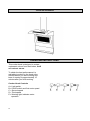
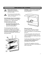
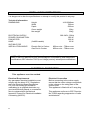
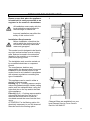
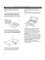
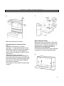
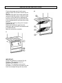
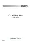
OPERATING AND INSTALLATION INSTRUCTIONS
ZANUSSI
ZHC72X
COOKER HOOD
IMPORTANT SAFETY INFORMATION
These warnings are provided in the interests of your safety. Ensure that you understand
them all before installing or using this appliance. Your safety is of paramount
importance. If you are unsure about any of the meanings of these warnings contact the
Customer Care Department.
Installation
•
Any installation work must be
undertaken by a qualified electrician
or competent person.
•
This hood must be installed in
accordance with the installation
instructions and all measurements
adhered to.
•
If the cooker hood is installed for use
above a gas appliance then the
provision for ventilation must be in
accordance with the Gas Safety Code
of Practice BS.6172, BS.5440 and
BS.6891 (natural gas) and BS.5482
(LP gas) 1994, the Gas Safety
(Installation & Use) Regulations, the
Building Regulations issued by the
Dept. of the Environment, the
Building Standards (Scotland)
(Consolidated) Regulations issued by
the Scottish Development
Department.
•
The fan motor of the cooker hood
incorporates a cut-out device, which
will operate if the cooker hood is
installed below the minimum height
recommended in the Technical
Information section, or if the motor
becomes overheated. If the cut-out
device is activated, switch off the
motor and allow the hood to cool.
The cut-out device will reset itself
when the fan motor has cooled.
•
It is dangerous to alter the
specifications or modify this product
in any way.
•
When installed between adjoining
wall cabinets, the cabinets must not
overhang the hob.
•
If the room where the hood is to be
used contains a fuel burning
appliance such as a central heating
boiler then its flue must be of the
room sealed or balanced flue type.
2
•
•
•
•
If other types of flue or appliances are
fitted ensure that there is an
adequate supply of air to the room.
When the hood is used in conjunction
with appliances supplied with energy
other than electricity, the negative
pressure in the room must not exceed
0.04mbar to prevent fumes being
drawn back into the room by the
hood.
The ducting system for this appliance
must not be connected to any existing
ventilation system which is being
used for any other purpose.
Do not install above a cooker with a
high level grill.
Child Safety
•
The appliance is designed to be
operated by adults. Children should
not be allowed to tamper with the
controls or play with the appliance.
During Use
•
This appliance is for domestic use
only.
•
Never leave frying pans unattended
during use as over-heated fats and
oils might catch fire.
•
Never do flambé cooking under this
cooker hood.
•
Do not leave naked flames under this
hood.
Maintenance and Service
•
This appliance can be a fire hazard if
the grease and charcoal filters are not
cleaned or replaced as
recommended.
•
Under no circumstances should you
attempt to repair the appliance
yourself. Repairs carried out by
inexperienced persons may cause
injury or serious malfunctioning.
Refer to your local Zanussi Service
Force Centre. Always insist on
genuine spare parts.
CONTENTS
For the User
Important Safety Information
Your Appliance
Operating Instructions
Maintenance and Cleaning
Something Not Working
Service and Spare Parts
Customer Care Department
Guarantee Conditions
For the Installer
2
4
4
5
6
6
6
7
Technical Information
Electrical Connections
Installing the Cooker Hood
8
8
9
3
YOUR APPLIANCE
OPERATING INSTRUCTIONS
This cooker hood is designed to extract
unpleasant odours from the kitchen, it will
not extract steam.
To obtain the best performance it is
advisable to switch on the hood a few
minutes before you start cooking and
leave it running for approximately 15
minutes after you finish cooking.
Cooker Hood Controls
A = Light switch
B = On/Off switch and first motor speed
C = Second speed
D = Third speed
E = Warning light; indicates motor
operation
4
MAINTENANCE AND CLEANING
Before carrying out any
maintenance or cleaning
isolate the cooker hood from
the mains supply.
WARNING: There is a third metallic filter
(not visible) which can be accessed
through opening R.
The cooker hood must be kept
clean, a build up of grease or fat
can be a fire hazard.
If you have the cooker hood operating in
the re-circulation mode, it is necessary to
change the charcoal filters (N) regularly
according to use. They should be
changed at least twice a year.
To remove the charcoal filters:
take off the anti-grease grilles as
described in the installation section.
lift the two metallic stops (P).
remove the charcoal filter.
The 2 anti-grease filters are easily
removed from the grille by following the
instructions and lifting the two metallic
stops (P). If you are using the hood in the
re-circulation mode, you will need to
remove the charcoal filter to access the
anti-grease filters.
External Cleaning
Any fat deposits should be removed
regularly, at least every two months.
Avoid using abrasive or corrosive cleaning
products.
To clean the outside of the cooker hood,
use a cloth dipped in lukewarm water to
which a small amount of washing up liquid
has been added.
To clean the steel, brass or copper parts
on the outside of the appliance, use a
proprietary cleaner and follow the
manufacturer’s instructions.
The inside of the appliance should be
cleaned with a soft cloth or brush dipped in
warm soapy water.
5
SOMETHING NOT WORKING
If, having carried out these instructions carefully, your cooker hood fails to work properly please
carry out the following checks.
Symptom
Solution
The cooker hood will not start
Check that the hood is connected to the
electricity supply.
Check that the fan speed control is on.
The cooker hood is not working effectively
Is the fan speed high enough for the task?
Is the grease filter clean?
Is the kitchen adequately vented to allow
the entry of fresh air.
If set up for re-circulation, check that the
charcoal filter is still effective.
If set up for extraction, check that the
ducting and outlets are not blocked.
The cooker hood has switched off during
operation
Has the safety cut-out tripped? Turn off the
hob and wait for the device to reset
If after all these checks, the problem
persists, contact your local Service Force
Centre, quoting the model number and
serial number.
In-guarantee customers should ensure
that the above checks have been made
as the engineer will make a charge if
the fault is not a mechanical or
electrical breakdown.
Please note that it will be necessary to
provide proof of purchase for any inguarantee calls.
SERVICE AND SPARE PARTS
If you require an engineer or wish to
purchase spare parts contact your local
Service Force Centre by telephoning:
08705 929929
Your telephone call will be routed to the
Service Force Centre covering your
postcode area.
For general assistance with your appliance
or for information on other Zanussi
6
products please contact our Customer
Care Department.
Customer Care Department
Zanussi
55-77 High Street
Slough
Berkshire
SL1 1DZ
Telephone: 08705 727727 *
* calls to this number may be recorded for
training purposes
GUARANTEE CONDITIONS
Standard Guarantee Conditions
We, Zanussi, undertake that if within 24 months of the date of the purchase this Zanussi built-in
appliance or any part thereof is proved to be defective by reason only of faulty workmanship or
materials, the company will, at our option, repair or replace the same FREE OF ANY CHARGE
for labour, materials and carriage on condition that:
•
The appliance has been correctly installed and used only on the electrical supply stated on
the rating plate.
•
The appliance has been used for normal domestic purposes only, and in accordance with
the manufacturer’s operating and maintenance instructions.
•
The appliance has not been serviced, maintained, repaired, taken apart or tampered with
by any person not authorised by us.
•
All service work under this guarantee must be undertaken by a Zanussi Service Force
Centre.
•
Any appliances or defective parts replaced shall become the property of this company.
Home visits are made between 8.30am and 5.30pm Monday to Friday. Visits may be available
outside these hours in which case a premium will be charged.
EXCLUSIONS
This Guarantee does not cover:
•
Damage or calls resulting from transportation, improper use or neglect, the replacement of
any light bulbs or removable parts of glass or plastic.
•
Costs incurred for calls to put right appliances improperly installed or calls to appliances
outside the United Kingdom.
•
Appliances found to be in use within a commercial environment, plus those which are the
subject of rental agreements.
•
Products of Zanussi manufacture which were not marketed by Zanussi Ltd.
This guarantee is in addition to your statutory and legal rights.
ZANUSSI EUROPEAN GUARANTEE
If you move to another country within Europe then your guarantee moves with you to your new
home subject to the following qualifications:
•
The guarantee starts from the date you first purchased your product.
•
The guarantee is for the same period and to the same extent for labour and parts as exists
in the new country of use for this brand or range of products.
•
The product is installed and used in accordance with our instructions and is only used
domestically, i.e. a normal household.
•
The product is installed taking into account regulations in your new country.
Before you move please contact your nearest Customer Care centre, listed below, to give them
details of your new home. They will ensure that the local Service organisation is aware of your
move and able to look after you and your appliance.
France
Germany
Italy
Sweden
UK
Senlis
Nurnberg
Pordenone
Stockholm
Slough
+33 (0)3 44 62 29 99
+49 (0)911 323 2600
+39 (0)01678 47053
+46 (0)8 738 79 50
+44 (0)1753 219897
7
INSTALLATION INSTRUCTIONS
It is dangerous to alter the specifications or attempt to modify this product in any way.
Technical Information
DIMENSIONS
Height
Width
Depth
1410-2340mm
700mm
500mm
Gross weight
Net weight
ELECTRICAL SUPPLY:
POWER CONSUMPTION:
FAN MOTOR:
LAMP:
SUITABLE FOR
INSTALLATION ABOVE:
23kg
20kg
220-240V (50Hz)
280 W
200 W
80 W
(2x40W candle)
Electric Slot-In Cooker:
Gas Slot-In Cooker:
650mm min – 750mm max
650mm min – 750mm max
NOTE: CE marking certifies that this appliance complies with the requirements laid
down in the EEC directive 89:336 (Electromagnetic Compatibility) and subsequent
modifications; EEC directive 73/23 (Low Voltage) and any subsequent modifications.
ELECTRICAL CONNECTION
This appliance must be earthed.
Electrical Requirements
Any permanent electrical installation must
comply with the latest I.E.E. Regulations
and local Electricity Board Regulations.
For your own safety this should be
undertaken by a qualified electrician e.g.
your local Electricity Board, or a contractor
who is registered with the National
Inspection Council for Electrical Installation
Contracting (NICEIC).
8
Electrical Connection
Before connecting to the mains supply
ensure that the mains voltage corresponds
to the voltage on the rating plate of the
cooker hood.
This appliance is fitted with a 13 amp plug.
This appliance conforms to EEC Directive
No 78 308 regarding suppression of radio
and television.
INSTALLING THE COOKER HOOD
Please ensure that when the appliance
is installed it is easily accessible to an
engineer in the event of a breakdown.
1
All installation must comply with the
local authorities requirements for
the discharge of exhaust air.
Incorrect installation may affect the
safety of this cooker hood.
Installation Requirements
Before installation, check that the
wall to which the cooker hood is to
be fitted for electricity cables and
water and gas pipes.
This cooker hood is designed to be fixed to
any rigid vertical surface over a cooking
area, and can be used in the extraction
(ducted to the outside) or re-circulation
(internal recycling) mode.
2
The installation work must be carried out
by a qualified electrician or competent
person.
The manufacturer declines any
responsibility for damages due to incorrect
installation of the cooker hood or if the
cooker hood is not installed in compliance
with relevant regulations controlling this
type of installation.
This appliance can be used in either a
ducting or filtering mode.
Ducting (fig.1) – Cooking vapours and/or
odours are passed straight outside (ceiling
and/or wall) via a disposal duct, using the
holes that are on the top and/or the back
of the appliance.
Filtering (fig.2) – Cooking vapours and/or
odours are removed from the air by 2
charcoal filters and the air is then recirculated around the room from the front
vents.
ATTENTION: For the filtering option it is
absolutely necessary to use the charcoal
filters but not for the ducting option.
Charcoal filters are available from your
local Zanussi Service Force Centre:
Part No. 942 640 157
9
INSTALLATION INSTRUCTIONS
Before assembling the appliance, it is
necessary to take off the anti-grease
grilles.
To remove the first grille, push it towards
the rear of the apparatus by using the
finger points so that it is released (fig.3).
To take it off completely, rotate it on one
side while keeping the other one steady.
Wall Fitting
Fix the telescopic part (A) with some
adhesive tape (W) so that it cannot slip out
(fig. 5).
Fix the lower part to the upper part of the
hood by using the screws supplied (fig. 5).
5
3
If installing the appliance in the ducting
mode, connect one of the two discharge
outlets to the external ducting and seal the
other opening with the cap supplied (fig.4).
4
If installing the appliance in the filtering
mode, both discharge outlets must be
blanked off using the caps supplied.
10
Using the drilling template fit two of the
screw anchors supplied to the wall,
corresponding to holes B (fig. 6). Insert
two of the screws supplied and hook the
hood in place using the holes B at the
back (fig. 6).
Before fully tightening the screws, mark
the position of the two holes C on the wall
with a marking pen. Unhook the hood and
drill the two holes in the marked positions
and insert the screw anchors. Hook the
hood back into place and finally secure it
with the four screws.
Remove the adhesive tape from the
telescopic part and pull it downwards until
it touches the hob.
INSTALLATION INSTRUCTIONS
6
Make the electrical connection.
Assembling the telescopic flue
(fig. 7)
Fix the lower bracket (D) onto the
apparatus. Fix the upper bracket (E) into
the ceiling; in order to position the bracket
on the same access as the apparatus,
refer to the small triangle (F) that is on the
central axis.
Take the two telescopic pipes,
remembering that you have to slightly lift
the smaller pipe (the lower one); insert the
pipes from the front expanding slightly with
your hands so that they can be hooked
onto the two brackets.
Fix the pipes to the brackets using screws
G and H.
7
Wall cupboard fitting
Make four holes in the bottom of the wall
cupboard and if operating the hood in the
ducting mode, cut the air venting hole. If
the hood is to be used in the filtering
mode, this is not necessary.
Fix the hood to the bottom of the cupboard
using the four screws supplied (fig.8).
8
11
INSTALLATION INSTRUCTIONS
Fix the telescopic part (A) with some
adhesive tape (W) so that it cannot slip out
(fig. 9).
Rest the lower part of the hood against the
wall and mark the position of the two holes
C (fig. 9) on the wall with a marking pen.
Remove the lower part and drill two holes
in the marked position and insert the screw
anchors.
Fix the lower part by using the 6 screws
supplied (fig. 9).
Remove the adhesive tape from the
telescopic part and pull it downwards until
it touches the hob.
Make the electrical connection.
9
IMPORTANT:
Check the position of screw M (fig.10).
Ducting – The screw(s) must be
completely screwed in.
Filtering – The screw(s) must not be
screwed in, so that the air sucked into the
hood can escape through the top vents.
10
13
14
15
© Electrolux Household Appliances Limited 2000