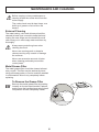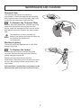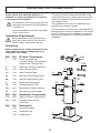
1
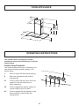
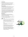
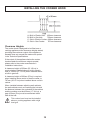
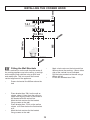
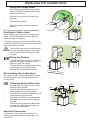
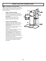
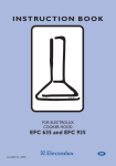
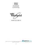
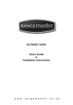
INSTRUCTION BOOKLET
COOKER HOOD
ZHC 935
Thank you for buying a Zanussi product.
To enable you to use your appliance effectively and safely, please read this instruction book
carefully before using the appliance and retain for future reference. If you require guidance in
the use of the appliance or require further information on Zanussi Products, please contact
our Customer Care Department.
Customer Care Department
Zanussi
55 - 77 High Street
Slough
Berkshire
SL1 1DZ
Tel: 08705 727 727
To register ownership, please ensure you complete and return the guarantee card supplied with the appliance.
For the User
For the Installer
Technical Information
Important Safety Information
Electrical Connection
Your Appliance
Electrical Requirements
Electrical Connection
Operating Instructions
Cooker Hood Controls
To Operate
Recirculation
Extraction
Installing the Cooker Hood
Installation Requirements
Unpacking
Clearance Heights
Fitting the Wall Brackets
Fitting the Canopy Hood
Venting
Recirculation
Fitting the Chimney Stack
Maintenance and Cleaning
External Cleaning
Metal Grease Filters
Charcoal Filters
To Remove/Replace the Charcoal Filters
Changing the Light Bulb
Something Not Working
Service and Spare Parts
Guarantee Conditions
Guide to use the instruction book
The following Symbols will be found in the text to guide you through the instruction book
Safety instructions
Step by step instructions
2
IMPORTANT SAFETY INFORMATION
These warnings are provided in the interests of safety. Ensure that you understand them all before installing or using this appliance. Your safety is of paramount importance. If you are unsure
about any of the meanings of these warnings contact the Customer Care Department.
•
•
Installation
•
This hood must be installed in accordance
with the installation instructions and all
measurements must be adhered to.
•
If the cooker hood is installed for use above
a gas appliance then the provision for
ventilation must be in accordance with the
Gas Safety Codes of Practice BS.6172,
BS.5440 and BS.6891 (Natural Gas) and
BS.5482 (LP Gas) 1994, the Gas Safety
(Installation & Use) Regulations, the
Building Regulations issued by the
Department of the Environment, the Building
Standards (Scotland) (Consolidated)
Regulations issued by the Scottish
Development Department.
•
•
The ducting system for this appliance must
not be connected to any existing ventilation
system which is being used for any other
purpose.
•
Do not install above a cooker with a highlevel grill.
•
•
Child Safety
•
•
During Use
•
Never leave frying pans unattended during
use as overheated fats and oils might catch
fire.
•
Never do flambé cooking under this cooker
hood.
•
Do not leave naked flames under the cooker
hood.
•
•
Maintenance and Service
•
Under no circumstances should you attempt
to repair the appliance yourself. Repairs
carried out by inexperienced persons may
cause injury or more serious malfunction.
Refer to your local Zanussi Service Force
Centre. Always insist on genuine spare parts.
Any installation work must be undertaken
by a qualified electrician or a competent
person.
The fan motor of this cooker hood
incorporates a cut-out device which will
operate if the cooker hood is installed below
the height recommended under the section
‘Clearance Height’, or if the motor becomes
overheated. If the cut-out device is activated,
switch off the fan motor and allow the cooker
hood to cool. The cut-out device will reset
itself when the fan motor has cooled
significantly.
•
It is dangerous to alter the specifications or
modify this product in any way.
•
When installed between adjoining wall
cabinets the wall cabinets must not overhang
the hob.
•
If the room where the cooker hood is to be
used contains a fuel burning appliance such
as a central heating boiler then its flue must
be of the room sealed or balanced flue type.
•
If other types of flue or appliances are fitted
ensure that there is an adequate supply of air
to the room.
3
This appliance is designed to be operated by
adults. Children should not be allowed to
tamper with the appliance.
This product is for domestic use only.
This appliance can be a hazard if the grease
filters and charcoal filters are not cleaned
and replaced as recommended.
YOUR APPLIANCE
265
740
740 min
950 max
433
300
500
73
898
OPERATING INSTRUCTIONS
This cooker hood is designed to extract
unpleasant odours from the kitchen, it will not
extract steam.
Cooker Hood Controls
The cooker hood functions are controlled by five
push button switches located centrally in the
control fascia.
L
Push to switch ON the worktop lighting.
S
Red neon indicates the fan motor is
switched ON.
V1
Push to switch ON the motor at the low
speed, for use with one burner or
when simmering.
V2
Push to engage the medium speed, for
normal cooking up to four pans.
V3
Push to engage the high speed, for use
when frying or cooking foods with
strong odours.
L
0-1
S
4
V1
MID
V2
MAX
V3
0-1
To Operate
Select the required fan speed and light if required.
The appliance can be installed to recirculate or
extract contaminated air. The cooker hood is more
effective when used in the extraction mode.
Recirculation
The cooker hood is supplied specified for use in the
recirculation mode with the charcoal filter fitted.
The contaminated air is cleaned by passing through
the filters and then back into the kitchen.
The activated charcoal filter absorbs odours arising
from cooking. In use it will slowly become saturated
in grease and less effective. The filter normally
requires changing at least every three months or
more frequently if the hood is used for more than
three hours per day.
Extraction
The contaminated air enters the cooker hood
passing through the grease filters and out through
the ducting into the atmosphere.
When used in the extract mode the charcoal filter is
not required and must be removed.
Never do flambé cooking under this cooker
hood.
Take extra care when frying and never leave
frying pans unattended during use, as overheated fats and oils can catch fire.
Do not leave naked flames under the cooker
hood.
Ensure the hood is switched ON before
using the hob.
Ensure heating areas on your hob are
covered with pots and pans when using the
hob and cooker hood simultaneously.
Ensure not to damage the charcoal filter
when cleaning or replacing as the activated
charcoal inside is saturated with grease,
which will stain if it comes into contact with
clothing or furnishings.
5
MAINTENANCE AND CLEANING
Before carrying out any maintenance or
cleaning isolate the cooker hood from the
mains supply.
The cooker hood must be kept clean, as a
build up of grease or fat can be a fire
hazard.
External Cleaning
The metal casing, visor and chimney should be
cleaned at least once a month to keep the hood
looking like new. Wipe over the hood with a soft
cloth wrung out in mild soapy water and then dry
thoroughly.
Always wear protective gloves when
cleaning the hood.
Never use scouring pads or abrasive
cleaners as they may scratch of damage
the surfaces.
Never use excessive amounts of water
when cleaning particularly around the
control panel.
Metal Grease Filter
The metal grease filter should be cleaned at least
every month. The filter may be washed by hand
using mild soapy water, or can be machine washed
in a dishwasher. Allow to dry completely before
replacing.
To Remove the Grease Filter
Remove the metal grease filter by pushing
inwardly on the two steel handles; replace,
making sure the handles have sprung back
into position and are completely visible.
6
MAINTENANCE AND CLEANING
Charcoal Filter
The charcoal filter cannot be cleaned or
regenerated, it should be replaced approximately
every three months or more frequently if the hood
is used for more than three hours per day.
To Remove the Charcoal Filter
Remove the metal grease filter. Release the fixing
hooks and remove the charcoal filter from the
recess. Insert the replacement filter into the recess
and replace the hooks. Replace the metal grease
filter.
This appliance can be a possible fire
hazard if the grease and charcoal filters are
not cleaned and replaced as
recommended.
Worktop Lighting
The lamps should be replaced with a 230V 20W
halogen spot lamp.
To Replace the Lamps
Unscrew the two screws to release the metal
surround. Remove the lamp from the holder by
pulling the lamp downwards.
Replace the spot lamp with an identical
replacement. When fitting the new lamp ensure the
two pins are properly inserted into the slots in the
lamp holder.
Charcoal filters, grease filters and lamps can be
obtained from your local Service Force Centre.
7
SOMETHING NOT WORKING
If, having followed these instructions carefully, your cooker hood fails to work properly please carry out
the following checks.
Symptom
Solution
The cooker hood will not start
•
Check the hood is connected to the electricity
supply.
•
•
•
•
Make sure the switch is in the ‘ON’ position.
•
If set up for recirculation, check that the
charcoal filter is still effective.
•
If set up for extraction, check that the ducting
outlets are not blocked.
•
•
The safety cut-out device has been tripped.
The cooker hood has switched off during
operation
If after all these checks, the fault persists, contact
your local Service Force Centre, quoting the
model and serial number.
The fan speed is set high enough for the task.
The grease filter is clean.
The kitchen is adequately vented to allow the
entry of fresh air.
Turn off the hob and then wait for the device
to reset.
In-guarantee customers should ensure that
the above checks have been made as the
engineer will make a charge if the fault is not a
mechanical or electrical breakdown.
Please note that it will be necessary to provide
proof of purchase for any in-guarantee service
calls.
SERVICE AND SPARE PARTS
If you require an engineer or spare parts contact
your local Service Force Centre by telephoning:
For general assistance with your appliance or for
further information on Zanussi products please
contact our Customer Care Department.
08705 929929
Customer Care Department
Zanussi
55 - 77 High Street
Slough
Berkshire
SL1 1DZ
Your telephone call will be routed to your local
Service Force Centre. For the address of your
local Service Force Centre and further information
about Service Force, please visit the website at
www.serviceforce.co.uk
Telephone: 08705 727 727*
* calls to this number may be recorded for training
purposes.
8
GUARANTEE CONDITIONS
We, Zanussi, undertake that if within twenty four months of the date of the purchase this Zanussi built-in
product or any part thereof is proved to be defective by reason only of faulty workmanship or materials, the
company will, at our option repair or replace the same FREE OF ANY CHARGE for labour, materials or
carriage on condition that:
•
The appliance has been correctly installed and used only on the electrical supply stated on the rating
plate.
•
The appliance has been used for normal domestic purposes only, and in accordance with the
manufacturer’s operating and maintenance instructions.
•
The appliance has not been serviced, maintained, repaired, taken apart or tampered with by any person
not authorised by us.
•
•
All service work under this guarantee must be undertaken by a Zanussi Service Force Centre.
Any appliance or defective part replaced shall become the property of this company.
Home visits are made between 8.30am and 5.30pm Monday to Friday. Visits may be available outside
these hours in which case a premium will be charged.
EXCLUSIONS
This Guarantee does not cover:
•
Damage or calls resulting from transportation, improper use or neglect, the replacement of any lamps
or removable parts of glass or plastic.
•
Costs incurred for calls to put right appliances improperly installed or calls to appliances outside the
United Kingdom.
•
Appliances found to be in use within a commercial environment, plus those which are the subject of
rental agreements.
•
Products of Zanussi manufacture which are not marked by Zanussi.
This guarantee is in addition to your statutory and legal rights.
ZANUSSI EUROPEAN GUARANTEE
If you should move to another country within Europe then your guarantee moves with you to your new
home subject to the following qualifications:
•
•
The guarantee starts from the date you first purchased the product.
•
•
•
This guarantee relates to you and cannot be transferred to another user.
The guarantee is for the same period and to the same extent for labour and parts as exists in the new
country of use for this brand or range of products.
Your new home is within the European Community (EC) or European Free Trade Area.
The product is installed and used in accordance with our instructions and is only used domestically, i.e.
a normal household.
Before you move please contact your nearest Customer Care Centre, listed below, to give them
detailsof your new home. They will then ensure that the local Service Organisation is aware of your
move and able to look after you and your appliances.
France
Germany
Italy
Sweden
United Kingdom
Senlis
Nurnberg
Pordenone
Stockholm
Slough
+33 (0)3 44 62 22 22
+49 (0)911 323 2600
+39 (0)1678 47053
+46 (0)20 78 77 50
+44 (0)1753 219897
9
INSTALLATION INSTRUCTIONS
It is dangerous to alter the specifications or attempt to modify this product in any way.
Technical information
DIMENSIONS
HEIGHT OF CANOPY:
HEIGHT OF CHIMNEY:(UPPER SECTION)
(LOWER SECTION)
WIDTH OF CANOPY:
DEPTH OF CANOPY:
WEIGHT: (GROSS)
WEIGHT: (NET)
ELECTRICAL SUPPLY
VOLTAGE:
(~50Hz)
POWER CONSUMPTION:
FAN MOTOR:
LAMPS:
(2 x20W Halogen)
SUITABLE FOR INSTALLATION ABOVE:
(MAX)
ELECTRIC HOB:
73mm
215mm
740mm
898mm
500mm
24.00kg
19.40kg
230V
240W
200W
40W
7KW
GAS HOB:
SLOT-IN ELECTRIC COOKER:
SLOT-IN GAS COOKER:
10KW (MAX)
12.4KW (MAX)
13.5KW (MAX)
Note: CE Marking certifies that this appliance complies with the
requirements laid down in EEC directive 89:336 (Electromagnetic
compatibility) and subsequent modifications and Low Votage directive
72/23/E.
THIS APPLIANCE MUST BE EARTHED
Electrical Requirements
This appliance is fitted with a 3 core mains cable
and must be permanently connected to the
electricity supply via a double-pole switch having
3mm minimum contact gap on each pole. A
Switched Fuse Connection Unit to BS.1363 Part
4, fitted with a 3 Amp fuse, is a recommended
mains supply connection accessory to ensure
compliance with the Safety Requirements
applicable to fixed wiring instructions.
Any permanent electrical installation must
comply with the latest I.E.E. Regulations and
local Electricity Board regulations. For your own
safety this should be undertaken by a qualified
electrician e.g. your local Electricity Board, or a
contractor who is on the roll of the National
Inspection Council for Electrical Installation
Contracting (NICEIC).
Electrical Connection
This appliance conforms to BS.800:1988 and EEC
Directive No. 78 308 regarding suppression of
radio and television interference.
Before connecting to the mains supply ensure
that the mains voltage corresponds to the voltage
on the rating plate inside the cooker hood.
10
INSTALLING THE COOKER HOOD
Please ensure that when the appliance is
installed it is easily accessible to an engineer
in the event of a breakdown.
This cooker hood is designed to be fixed to any
vertical surface over a cooking area, and can be
used in the extraction (ducted to the outside) or
recirculation mode.
The installation work must be undertaken by a
qualified and competent person.
All installations must comply with the local
authorities requirements for the discharge
of exhaust air.
The manufacturer disclaims any responsibility for
damage due to incorrect installation of the cooker
hood or if the hood is not installed in compliance
with relevant regulations controlling this type of
installation.
Incorrect installation may affect the safety
of this cooker hood.
Installation Requirements
Before installation check that the wall to
which the cooker hood is to be fitted for
electric cables, water pipes and gas.
Unpacking
Before unpacking the cooker hood position the
carton with the arrows pointing upwards as
illustrated on the carton.
15
Ref: Qty: Product Components
1
1 No
Canopy complete with:
Controls, Lighting, Fan Assembly,
Grease Filter, Charcoal Filter.
2
1 No
Telescopic Chimney comprising:
2.1
1 No
Upper Chimney Stack
2.2
1 No
Lower Chimney Stack
8a
1 No
Right-Hand Recirculation grille
8b
1 No
Left-Hand Recirculation grille
9
1 No
Ø150-120 Ducting Spigot
14
1 No
Ducting Extension Pipe
14.1
2 No
Recirculation Outlet Extentions
15
1 No
Recirculation Outlet Adapter
14.1
7.2.1
14
9
2.1
8b
2.2
Ref: Qty: Installation Components
7.2.1
2 No
Upper Chnimey Fixing Brackets
12c
6 No
Chimney Fixing Screws
2.9x6.5mm
Ref: Qty: Documents
1 No
Instruction Booklet
1 No
Guarantee Card
1 No
Questionnaire
12c
2
1
11
8a
INSTALLING THE COOKER HOOD
A: Built-in Electric Hob: 650mm clearance
B: Built-in Gas Hob:
700mm clearance
C: Slot-in Electric Cooker: 685mm clearance
D: Slot-in Gas Cooker:
767mm clearance
Clearance Heights
The cooker hood is designed to be fitted over a
cooking appliance at the clearance heights stated,
providing the maximum output of the appliance
beneath does not exceed the maximums quoted
in the Technical Specifications.
If the output of the appliance below the cooker
hood exceeds the maximum outputs quoted,
please refer to the cooker manufacturer’s
installation instructions.
A clearance height of 650mm (25 1/2 ins) is
required when installed above a built-in electric
hob, or 700mm (27 1/2 ins) when installed above
a built-in gas hob.
A clearance height of 685mm (27ins) is required
when installing above a slot-in electric cooker, or
787mm (30 1/2 ins) when installed above a slot-in
cooker.
When installed between adjoining wall cabinets,
the wall cabinets must not overhang the hob and
the distance between the underside of the cabinet
and the worktop must be 450mm (17 3/4 ins), a
gap of 50mm (2ins) must be maintained either
side of the hob.
This cooker hood must not be installed
above a cooking appliance with a high
level grill.
12
1-2 mm
INSTALLING THE COOKER HOOD
X
7.2.1
965
965 min.
116 116
Fitting the Wall Brackets
-
Draw a vertical line on the wall from the centre of
the cooking appliance up to the ceiling, or as high
as the adjoing wall cabinets using a spirit level
and marker pen. This is to ensure the correct
vertical alignment of the appliance.
-
-
Draw a horizontal line 965mm above the
hob
-
Place bracket item 7.2.1 on the wall as
shown about 1-2mm from the ceiling or
upper limit aligning-notch in the centre of
the bracket with the vertical line.
Mark the hole centres for the bracket
fixing screws on the wall.
Place bracket item 7.2.1 on the wall as
shown at 215mm below the first bracket
at X.
Mark the hole centres for the bracket
fixing screws on the wall.
-
-
-
13
Mark a hole centre on the horizontal line
965mm above the worktop, 116mm either
side of the vertical line as indicated.
Drill the holes marked on the wall using a
Ø8mm drill-bit.
Fix the two brackets item 7.2.1.
INSTALLING THE COOKER HOOD
Fitting the Canopy Hood
Before starting to fix the canopy, tighten
the two screws Vr located on the canopy
mouiunting brackets.
-
Hook the canopy onto the screws (not
supplied).
-
Tighten up the screws.
-
Adjust the screws item Vr to level the
canopy.
Vr
The fixings come together with the splashback.
Ducting the Cooker Hood
When installing the cooker hood in the ducting
mode, connect the hood using either Ø150 or
120mm flexible or rigid pipe.
The choice of ducting should be specified by the
installer but Ø150mm rigid ducting will ensure the
best performance possible.
The ducting used must be manufactured
from fire retardent material conforming
to the relevant British Standard or DIN
4102-B1.
ø 150
Fitting the Ducting
-
-
ø 120
9
To install Ø120mm ducting, fit the ducting
spigot Ø150-120mm item 9 on to the
spigot on top of the canopy.
To install Ø150mm ducting, fit the ducting
on the spigot on top of the canopy.
Remove the activated charcoal filter.
Recirculating the Cooker Hood
The cooker hood is supplied specified for use in
the recirculation mode, with the charcoal filter
already fitted.
Fitting the Recirculation Duct
-
-
Assemble the two halves of the ducting
extension pipe item 14.
Push-fit the extension pipe on to the
ducting spigot on top of the canopy.
Push-fit the recirculation adapter item 15
on to extension pipe item 14.
Insert the recirculation outlet extensions
item 14.4 into the recirculation adapter
item 15.
The recircualtion grilles item 8a and 8b
must be fitted after the lower chimney
item 2.2 has been fitted.
Electrical Connection
Connect the hood to the mains supply via a
double-pole switch having a contact gap of at
least 3mm.
15
14.1
8b
8a
14
INSTALLING THE COOKER HOOD
Fitting the Chimney Stack
The chimney consists of two sections. The upper
chimney measures 215mm and the lower chimney
(with the holes for recirculation on either side)
measures 740mm.
-
-
-
-
-
-
7.2.1
12c
Upper Chimney Stack
Expand the sides of the upper chimney
stack item 2.1 and place the chimney over
the two brackets 7.2.1 ensuring they are
well seated.
Secure the chimney stack to the
brackets 7.2.1 using the four self
tapping screws 12c - 2.0x6.5mm.
2.1
2
8b
8a
2.2
Lower Chimney Stack
Expand the of the lower chimney stack
item 2.2 and place the chimney over the
upper chimney stack item 2.1 and the
canopy item 1.
Secure the chimney stack to the canopy
using the two screws item 12c 2.9x6.5mm.
After the chimney has been secured into
position, insert the two plastic
recirculation grilles item 8a (right-hand)
and 8b (left-hand) in the apertures on
each side of the chimney. The grilles are
marked with two arrows and should be
fitted with one arrow pointing upwards and
the other toward the front.
When the hood is used in the recirculation
mode ensure that the grilles are properly
secured to the recirculation extension
spigot 14.1.
12c
15
16
17
18
© Electrolux plc 2002
436000659 02 - 020626