1
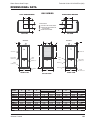
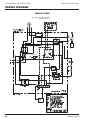
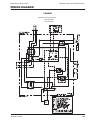
technical guide
Water Source
Heat Pumps
Technical Guide: YK145.00-EG4 (309)
Water Source Heat Pumps
TABLE OF CONTENTS
Introduction . . . . . . . . . . . . . . . . . . . . . . . . . . . . . . . . . . . . . . . . . . . . . . . . . . . . . . . . . . . . . . . . . . . . . . . . . . . . . . . 3
Product Overview . . . . . . . . . . . . . . . . . . . . . . . . . . . . . . . . . . . . . . . . . . . . . . . . . . . . . . . . . . . . . . . . . . . . . . . . . . 3
Specifications . . . . . . . . . . . . . . . . . . . . . . . . . . . . . . . . . . . . . . . . . . . . . . . . . . . . . . . . . . . . . . . . . . . . . . . . . . . . . 4
Nomenclature . . . . . . . . . . . . . . . . . . . . . . . . . . . . . . . . . . . . . . . . . . . . . . . . . . . . . . . . . . . . . . . . . . . . . . . . . . . . . 5
Physical Data . . . . . . . . . . . . . . . . . . . . . . . . . . . . . . . . . . . . . . . . . . . . . . . . . . . . . . . . . . . . . . . . . . . . . . . . . . . . . 6
ARI/ISO Performance Data . . . . . . . . . . . . . . . . . . . . . . . . . . . . . . . . . . . . . . . . . . . . . . . . . . . . . . . . . . . . . . . . . . 7
Performance Data . . . . . . . . . . . . . . . . . . . . . . . . . . . . . . . . . . . . . . . . . . . . . . . . . . . . . . . . . . . . . . . . . . . . . . . . . 8
Correction Factors . . . . . . . . . . . . . . . . . . . . . . . . . . . . . . . . . . . . . . . . . . . . . . . . . . . . . . . . . . . . . . . . . . . . . . . . 19
Blower Performance. . . . . . . . . . . . . . . . . . . . . . . . . . . . . . . . . . . . . . . . . . . . . . . . . . . . . . . . . . . . . . . . . . . . . . . 20
Electrical Data . . . . . . . . . . . . . . . . . . . . . . . . . . . . . . . . . . . . . . . . . . . . . . . . . . . . . . . . . . . . . . . . . . . . . . . . . . . 21
Dimensional Data . . . . . . . . . . . . . . . . . . . . . . . . . . . . . . . . . . . . . . . . . . . . . . . . . . . . . . . . . . . . . . . . . . . . . . . . . 22
Wiring Diagram. . . . . . . . . . . . . . . . . . . . . . . . . . . . . . . . . . . . . . . . . . . . . . . . . . . . . . . . . . . . . . . . . . . . . . . . . . . 24
2
Johnson Controls
Water Source Heat Pumps
Technical Guide: YK145.00-EG4 (309)
INTRODUCTION
Performance and dependability in a no-nonsense heat pump.
The R-Series units by YORK are completely self-contained heat pumps. This equipment employs a water-torefrigerant heat exchanger to extract (heating cycle) or reject (cooling cycle) heat from/to a circulating
water-loop.
The high-quality feature set delivers robust construction and reliable performance that exceeds ASHRAE 90.1
requirements. Available with an insulated refrigerant-circuit, the R-Series is equally suited for water-loop and lowtemperature, geothermal applications.
For commercial installations ranging from schools to multi-story office space, R-Series Water Source Heat Pumps
by YORK provide the performance and dependability necessary to suit today’s demanding installation
requirements.
Listings / Certifications
PRODUCT OVERVIEW
Refrigerant
R-410A
Sizes
.5 – 6 Tons
(1.76 – 21.1 kW)
Model
RSH (Horizontal)
RSV
(Vertical)
Johnson Controls
3
Technical Guide: YK145.00-EG4 (309)
Water Source Heat Pumps
SPECIFICATIONS
GENERAL
• Optional stainless steel drain pan.
All R-series models ½ - 6 ton ship as factory-charged
packages, complete with R-410A refrigerant. Horizontal
(RSH) units are designed for suspended ceiling mounting. RSH models are shipped with ‘straight-through’
evaporator fan discharge as standard. Fan orientation
is field convertible to side discharge.
The coaxial refrigerant-to-water heat exchangers feature a convoluted inner tube design for high heat
transfer efficiency. Standard models feature a copper
inner tube surrounded by a steel outer tube, and carry
a 400 psig water side working pressure rating. Units
shall be capable of operation with an entering fluid
temperature range of 20°F to 110°F.
Vertical (RSV) units are designed for free-standing floor
mounting. All units are completely factory wired and
pre-piped. Water supply, water outlet, and condensate
drain connections are via flush-mounted female pipe
thread fittings (no back-up wrench required).
CABINET
All cabinets are completely constructed of corrosion
resistant galvanized steel. The RSH units are complete
with integral hanger channels. The entire unit interior
(both evaporator and condensing section) is insulated
with 1/2″ thick, 2 lb density acoustical insulation. Service
panels are equipped with lifting handles for ease of
removal and handling. All units provide service access
to the reversing valve, thermal expansion valve, and
compressor with the unit remaining in location. An integral duct collar is provided on the blower discharge
opening.
REFRIGERATION CIRCUITS
All models utilize high efficiency rotary, hermetic reciprocating or scroll compressors. Compressors are
mounted with rubber isolators on acoustically tuned
bases to minimize vibration transmission. Internal overload protection is provided. External high pressure and
low pressure cutout switches are included in each
compressor control circuit. Each refrigeration circuit
includes an adjustable bi-flow thermal expansion valve
(with external equalizer), bi-flow liquid line filter drier,
and service gauge ports. The reversing valve is a pilot
operated, sliding piston type with a replaceable magnetic solenoid coil.
The refrigerant-to-air heat transfer coils are constructed
of internally enhanced copper tubes mechanically
bonded to enhanced aluminum plate fins. The evaporator coil is employed in a draw-through configuration.
Large evaporator coil face area minimizes potential
water blow-off. A fully-insulated, corrosion resistant
condensate drain pan is provided.
• Optional anti-corrosion protective evaporator coil
coating.
4
• Optional cupro-nickel condenser water coil.
• Optional condenser insulation package for lowwater temperature, geothermal applications.
INDOOR FAN
Forward curved, double inlet and double width, directdrive centrifugal blowers are used for air movement.
Large diameter wheels are employed to provide required
airflow performance at minimum noise levels. Blower
wheels are fabricated of galvanized steel. Fan motors
are PSC type, with minimum three speeds. The PSC
motors feature permanently lubricated bearings and
internal thermal overload protection.
ELECTRICAL/CONTROLS
All units are completely factory wired with all necessary
operating controls. A 24 volt control circuit, with oversized transformer, is provided for field connection. Units
are designed to operate with conventional heat pump
thermostat control interface. The reversing valve solenoid coil shall be energized in cooling mode only. A
manual reset is provided on each compressor control
circuit in the event of high/low pressure cutout.
• Optional solid-state electronic condensate overflow
switch.
• Optional remote management package allows the
unit to be controlled by an external source.
FILTERS
All models are shipped with 1-inch thick throwaway
filters, factory installed. Filters are accessible from
either side of unit.
FIELD INSTALLED ACCESSORIES
The following options are available field installation:
• 24″ braided stainless steel hose kit with fittings.
(qty 2 hoses per kit)
• Manual isolation ball-valves (600 psi full port).
• Thermostat (programmable or non-programmable)
Johnson Controls
Water Source Heat Pumps
Technical Guide: YK145.00-EG4 (309)
NOMENCLATURE
WATER SOURCE HEAT PUMP
1,2
3
4,5,6
7
8
9
10
11
12
13
14
15
RS H 018 A 2 E L S A A 0 A
Miscellaneous Options
A = None
Product Category
D = Condensate Overflow Switch
RS = Water-Cooled HP R-410A
Heating Options
0 = None
Product Indentifier
V = Vertical Arrangement (Upflow)
H = Horizontal Arrangment
Waterside Options
A = Std Water coil
B = Insulated Water Coil
N = Cupro-nickel Water Coil
R = Cupro-nickel & Insulation
Nominal Capacity
007 = .5 TON
009 = .75 TON
Airside Options
A = Std Airside coil
012 = 1 TON
C = Corrosion Protective Coating
D = Stainless Steel Drain Pan
F = Coated Coil w/ S-S Drain Pan
018 = 1.5 TON
024 = 2 TON
030 = 2.5 TON
036 = 3 TON
Design Series
042 = 3.5 TON
A = Current
Supply Air Options
048 = 4 TON
060 = 5 TON
070 = 6 TON
S = Straight-Thru (Horizontal Only)
B = Back Discharge (Horizontal Only)
T = Top Discharge (Vertical Only)
Voltage
Return Air/Unit Orientation
1 = 208/230-60-1
6 = 265-60-1
2 = 208/230-60-3
4 = 460-60-3
5 = 575-60-3
L = Left Hand
R = Right Hand
Control Options
E = Std Electromechnical Controls
K = Remote Management Relay Kit
Johnson Controls
5
Technical Guide: YK145.00-EG4 (309)
Water Source Heat Pumps
PHYSICAL DATA
Model Series
Nominal Cooling (Ton)
1
007
009
012
018
024
030
036
042
048
060
070
0.5
0.75
1.0
1.5
2.0
2.5
3
3.5
4
5
6
Rotary
Compressor-Type
Reciprocating
Scroll
Enhanced Copper tubes, Enhanced Aluminum Fins
Air Coil-Type
Face Area(sq ft)
1.17
1.17
1.33
2.56
2.88
2.88
3.47
4.44
4.44
6.11
6.11
Rows/FPI
3/13
3/13
3/15
3/15
3/15
3/15
3/15
3/15
3/15
3/15
3/15
3/4
3/4
1
1
Enhanced Surface Co-Axial
Water Coil-Type
Water Connection (in)
1/2
1/2
Motor HP
3/4
3/4
3/4
3/4
DWDI Forward-Curved Centrifugal / PSC Direct-Drive
Standard Blower/Motor
Diameter x Width (in)
1/2
6x5
6x5
6x6
9x7
9x7
10x7T
10x7T
11x8T
11x8T
0.10/3
0.10/3
0.13/3
0.17/3
0.25/3
0.33/3
0.50/3
0.50/3
0.75/3
11x10T 11x10T
1.0/3
1.0/3
RSH Filter
Quantity-Size(in)
1-12x16 1-12x16 1-12x20 1-18x24 1-18x24 1-18x24 2-14x20 2-18x20 2-18x20 2-22x22 2-22x22
RSV Filter
Quantity-Size(in)
1-12x20 1-12x20 1-12x20 1-18x24 1-20x25 1-20x25 1-24x24 2-14x25 2-14x25 2-16x30 2-16x30
RSH Cabinet Weight (lb)
130
135
145
195
210
215
240
310
320
370
385
RSV Cabinet Weight (lb)
120
125
135
185
200
210
230
305
315
375
390
NOTE:
1) Nominal Capacity calculated in accordance with ARI / ISO Standard 13256-1 for Water Loop Application
OPERATING LIMITS*
COOLING
HEATING
Min. Entering Water
30°F
20°F
Max. Entering Water
110°F
90°F
*Units are capable of operation with an entering fluid temperature
range of 20°F to 110°F
6
Johnson Controls
Water Source Heat Pumps
Technical Guide: YK145.00-EG4 (309)
ARI/ISO PERFORMANCE DATA
PERFORMANCE DATA - ARI/ISO 13256-1 WATER LOOP CONDITIONS*
Flow Rate
Air Flow
Cooling
(USGPM)
(SCFM)
Capacity (Btuh)
007
1.8
260
6,800
009
2.4
320
8,900
012
3.0
400
12,400
018
4.8
640
19,100
024
6.0
800
24,600
030
7.8
1000
29,800
036
9.0
1200
36,200
042
10.4
1400
42,700
048
12.0
1600
48,300
060
15.0
2000
60,500
070
17.5
2200
67,700
*Water Loop capacities are rated at 86°F EWT Cooling, 68°F EWT Heating.
Unit Model
EER
12.5
12.4
12.2
13.2
13.5
13.3
13.0
12.7
13.1
13.4
12.9
Heating
Capacity (Btuh)
8,700
11,600
15,600
23,400
29,300
35,300
45,100
50,600
57,200
70,800
79,500
COP
4.5
4.4
4.2
4.5
4.4
4.5
4.6
4.4
4.5
4.6
4.3
PERFORMANCE DATA - ARI/ISO 13256-1 GROUND WATER CONDITIONS*
Flow Rate
Air Flow
Cooling
EER
(USGPM)
(SCFM)
Capacity (Btuh)
007
1.8
260
7,700
18.4
009
2.4
320
10,100
18.3
012
3.0
400
14,200
18.1
018
4.8
640
22,900
20.2
024
6.0
800
28,700
20.8
030
7.8
1000
33,600
20.0
036
9.0
1200
39,800
18.8
042
10.4
1400
45,800
19.1
048
12.0
1600
52,500
19.3
060
15.0
2000
66,400
19.8
070
17.5
2200
73,600
18.7
*Ground Water capacities are rated at 59°F EWT Cooling, 50°F EWT Heating.
Unit Model
Heating
Capacity (Btuh)
6,900
9,100
12,900
18,800
23,600
29,100
37,200
42,300
47,400
59,000
66,800
COP
3.9
3.8
3.6
3.9
3.8
3.8
3.9
3.9
3.8
4.0
3.8
PERFORMANCE DATA - ARI/ISO 13256-1 GROUND LOOP CONDITIONS*
Flow Rate
Air Flow
Cooling
(USGPM)
(SCFM)
Capacity (Btuh)
007
1.8
260
7,100
009
2.4
320
9,300
012
3.0
400
13,000
018
4.8
640
20,600
024
6.0
800
26,400
030
7.8
1000
31,100
036
9.0
1200
37,500
042
10.4
1400
43,900
048
12.0
1600
49,800
060
15.0
2000
62,900
070
17.5
2200
70,100
*Ground Loop capacities are rated at 77°F EFT Cooling, 32°F EFT Heating.
Unit Model
EER
14.6
14.5
14.3
15.7
16.1
15.3
14.8
14.6
15.0
15.6
14.7
Heating
Capacity (Btuh)
5,500
6,900
10,200
13,900
17,400
22,500
28,600
32,300
37,800
47,200
52,400
COP
3.4
3.3
3.1
3.4
3.3
3.3
3.3
3.4
3.3
3.5
3.3
NOTE:
1) All Cooling capacities based upon 80.6°F DB, 66.2°F WB entering air temperature.
2) All Heating capacities based upon 68°F DB, 59°F WB entering air temperature.
Johnson Controls
7
Technical Guide: YK145.00-EG4 (309)
Water Source Heat Pumps
PERFORMANCE DATA
RS*007 — 320 CFM
WPD
COOLING
HEATING
EWT (F)
GPM
PSI
FT
20
1.8
4.8
11.0
1.0
2.1
4.9
8.5
6.0
0.30
9.5
1.4
2.8
6.4
8.7
6.1
0.28
9.7
1.8
4.2
9.8
8.8
6.1
0.26
1.0
1.8
4.3
8.1
5.8
1.4
2.4
5.6
8.3
5.9
1.8
3.7
8.5
8.4
1.0
1.6
3.8
1.4
2.1
4.9
1.8
3.3
1.0
1.4
30
40
50
60
70
80
90
100
110
TC
SC
kW
HR
EER
HTG
kW
HE
LAT (F)
COP
4.1
0.44
2.6
80
2.7
28.0
5.0
0.45
3.5
82
3.3
30.8
5.3
0.47
3.7
83
3.3
9.7
33.7
5.4
0.47
3.8
84
3.4
0.34
9.2
24.1
5.5
0.47
3.9
84
3.4
0.32
9.4
25.9
5.7
0.47
4.1
84
3.5
6.0
0.31
9.5
26.8
5.9
0.48
4.3
85
3.6
7.7
5.5
0.36
8.9
21.5
6.4
0.50
4.7
87
3.8
7.8
5.6
0.35
9.0
22.6
6.6
0.50
4.9
87
3.9
7.5
8.0
5.7
0.34
9.2
23.4
6.9
0.52
5.1
88
3.9
1.4
3.3
7.4
5.4
0.44
8.9
17.0
7.5
0.51
5.8
90
4.3
1.8
4.3
7.6
5.5
0.42
9.0
17.9
7.7
0.52
5.9
90
4.4
1.8
2.8
6.5
7.7
5.6
0.42
9.1
18.4
8.2
0.54
6.3
92
4.4
1.0
1.3
3.0
7.0
5.2
0.50
8.7
14.0
8.4
0.57
6.4
92
4.3
1.4
1.7
3.9
7.2
5.3
0.48
8.8
15.1
8.8
0.59
6.8
93
4.4
1.8
2.6
6.0
7.3
5.3
0.47
8.9
15.6
9.0
0.59
7.0
94
4.5
1.0
1.1
2.6
6.8
5.3
0.56
8.7
12.2
9.5
0.60
7.5
95
4.7
1.4
1.5
3.5
6.9
5.3
0.54
8.8
12.7
9.9
0.61
7.8
97
4.7
1.8
2.3
5.3
7.0
5.3
0.53
8.8
13.1
10.3
0.63
8.1
98
4.8
1.0
1.0
2.3
6.4
5.1
0.65
8.6
9.9
10.7
0.65
8.5
99
4.8
1.4
1.3
3.1
6.5
5.1
0.63
8.6
10.4
11.0
0.66
8.8
100
4.9
1.8
2.0
4.7
6.6
5.2
0.60
8.6
11.0
11.2
0.66
8.9
100
4.9
1.0
0.9
2.1
5.9
4.9
0.71
0.7
8.3
1.4
1.2
2.7
6.1
5.1
0.69
0.7
8.9
1.8
1.8
4.2
6.2
5.1
0.67
0.7
9.2
1.0
0.8
1.9
5.4
4.6
0.77
0.8
7.0
1.4
1.1
2.4
5.6
4.7
0.75
0.8
7.5
1.8
1.6
3.7
5.7
4.7
0.73
0.7
7.8
Cooling Performance is tabulated at 80.6 F DB and 66.2 F WB entering air. Heating performance tabulated at 68 F EAT
Tabulated data does not include ARI/ISO corrections for fan and pump power.
All capacities are expressed in MBH.
Insulated water circuit is recommended for operation below 60F EWT.
See performance correction tables for conditions beyond what is listed.
Extrapolation is not permissible.
Shaded areas indicate conditions where operation is not recommended.
8
Johnson Controls
Water Source Heat Pumps
Technical Guide: YK145.00-EG4 (309)
PERFORMANCE DATA
RS*009 — 320 CFM
WPD
COOLING
HEATING
EWT (F)
GPM
PSI
FT
20
2.4
7.0
16.1
1.2
2.6
6.0
12.8
9.0
0.47
14.4
1.8
4.1
9.6
13.1
9.1
0.43
14.6
2.4
6.0
13.9
13.2
9.1
0.40
1.2
2.3
5.2
12.5
8.9
1.8
3.6
8.3
12.7
9.0
2.4
5.2
12.1
12.9
1.2
2.0
4.6
1.8
3.2
7.4
2.4
4.6
1.2
1.8
30
40
50
60
70
80
90
100
110
TC
SC
kW
HR
EER
HTG
kW
HE
LAT (F)
COP
5.6
0.57
3.7
84
2.9
27.4
6.1
0.74
3.6
86
2.4
30.6
6.6
0.72
4.2
87
2.7
14.6
33.0
6.8
0.62
4.7
88
3.2
0.54
14.4
23.0
7.0
0.62
4.9
88
3.3
0.51
14.4
24.8
7.3
0.63
5.2
89
3.4
9.2
0.48
14.6
26.6
7.6
0.65
5.4
90
3.4
10.0
7.2
0.52
11.8
19.2
8.3
0.68
6.0
92
3.6
10.4
7.4
0.48
12.0
21.7
8.7
0.69
6.3
93
3.7
10.7
10.6
7.5
0.46
12.2
23.2
9.1
0.70
6.7
94
3.8
1.7
4.0
9.6
7.1
0.57
11.6
16.7
9.5
0.71
7.1
95
3.9
2.8
6.4
9.9
7.2
0.56
11.8
17.8
10.1
0.74
7.6
97
4.0
2.4
4.0
9.3
10.1
7.3
0.55
12.0
18.2
10.6
0.76
8.0
99
4.1
1.2
1.6
3.7
9.3
6.9
0.65
11.5
14.4
10.2
0.71
7.8
98
4.2
1.8
2.6
5.9
9.5
7.0
0.60
11.6
15.8
11.1
0.76
8.5
100
4.3
2.4
3.7
8.5
9.7
7.1
0.58
11.7
16.7
11.8
0.77
9.2
102
4.5
1.2
1.4
3.2
8.6
6.6
0.69
10.9
12.5
11.8
0.77
9.2
102
4.5
1.8
2.2
5.2
8.9
6.8
0.66
11.2
13.4
12.7
0.79
10.0
105
4.7
2.4
3.3
7.5
9.2
7.0
0.66
11.4
14.0
13.3
0.81
10.5
106
4.8
1.2
1.2
2.9
8.0
6.3
0.74
10.5
10.8
13.4
0.80
10.7
107
4.9
1.8
2.0
4.6
8.2
6.4
0.70
10.6
11.7
14.4
0.83
11.6
110
5.1
2.4
2.9
6.7
8.4
6.6
0.69
10.7
12.2
14.7
0.84
11.8
111
5.1
1.2
1.1
2.6
7.4
6.2
0.80
10.1
9.2
1.8
1.8
4.1
7.6
6.3
0.77
10.2
9.9
2.4
2.6
5.9
7.8
6.4
0.76
10.4
10.3
1.2
1.0
2.3
8.4
7.1
1.08
12.1
7.8
1.8
1.6
3.7
8.7
7.3
1.04
12.2
8.4
2.4
2.3
5.3
8.9
7.4
1.01
12.4
8.8
Cooling Performance is tabulated at 80.6 F DB and 66.2 F WB entering air. Heating performance tabulated at 68 F EAT
Tabulated data does not include ARI/ISO corrections for fan and pump power.
All capacities are expressed in MBH.
Insulated water circuit is recommended for operation below 60F EWT.
See performance correction tables for conditions beyond what is listed.
Extrapolation is not permissible.
Shaded areas indicate conditions where operation is not recommended.
Johnson Controls
9
Technical Guide: YK145.00-EG4 (309)
Water Source Heat Pumps
PERFORMANCE DATA
RS*012 — 400 CFM
WPD
COOLING
HEATING
EWT (F)
GPM
PSI
FT
20
3.0
3.9
9.0
1.5
2.0
4.5
16.9
11.8
0.53
18.7
2.3
2.6
6.1
17.1
11.9
0.49
18.8
3.0
3.4
7.9
17.2
11.9
0.48
1.5
1.7
3.9
16.2
11.6
2.3
2.3
5.3
16.5
11.7
3.0
3.0
6.9
16.6
1.5
1.5
3.5
2.3
2.0
4.7
3.0
2.6
1.5
2.3
30
40
50
60
70
80
90
100
110
TC
SC
kW
HR
EER
HTG
kW
HE
LAT (F)
COP
8.2
0.86
5.3
87
2.8
32.0
9.0
0.91
5.9
89
2.9
34.7
9.5
0.93
6.3
90
3.0
18.8
36.0
9.9
0.94
6.7
91
3.1
0.63
18.3
25.8
9.8
0.90
6.7
91
3.2
0.60
18.5
27.6
10.2
0.91
7.1
92
3.3
11.8
0.58
18.6
28.7
10.9
0.97
7.6
93
3.3
15.5
11.2
0.74
18.0
21.0
11.7
1.01
8.3
95
3.4
15.8
11.3
0.71
18.2
22.3
12.3
1.03
8.8
96
3.5
6.1
15.9
11.3
0.69
18.2
23.1
12.9
1.05
9.3
98
3.6
1.3
3.0
14.9
11.0
0.85
17.8
17.6
12.0
0.90
8.9
96
3.9
1.8
4.1
15.1
11.0
0.81
17.9
18.6
12.5
0.92
9.4
97
4.0
3.0
2.3
5.3
14.2
10.3
0.79
16.9
18.0
12.9
0.92
9.8
98
4.1
1.5
1.2
2.8
13.1
9.8
0.89
16.1
14.8
14.6
1.04
11.0
102
4.1
2.3
1.6
3.8
13.4
9.8
0.86
16.3
15.6
15.1
1.03
11.6
103
4.3
3.0
2.1
4.9
13.5
9.9
0.84
16.4
16.1
15.8
1.08
12.1
105
4.3
1.5
1.1
2.4
12.1
9.4
0.98
15.5
12.3
14.8
0.94
11.6
102
4.6
2.3
1.4
3.3
12.5
9.6
0.96
15.8
13.0
15.6
0.97
12.3
104
4.7
3.0
1.8
4.3
12.8
9.8
0.95
16.0
13.5
16.2
0.99
12.8
106
4.8
1.5
0.9
2.2
11.8
9.3
1.11
15.6
10.6
16.1
0.98
12.7
105
4.8
2.3
1.3
2.9
12.0
9.4
1.08
15.7
11.1
16.9
0.99
13.5
107
5.0
3.0
1.6
3.8
12.2
9.6
1.06
15.8
11.5
17.6
1.01
14.1
109
5.1
1.5
0.8
1.9
10.9
9.1
1.21
15.0
9.0
2.3
1.1
2.6
11.3
9.4
1.19
15.4
9.5
3.0
1.5
3.4
11.5
9.5
1.17
15.5
9.8
1.5
0.7
1.7
10.0
8.5
1.32
14.5
7.6
2.3
1.0
2.3
10.3
8.7
1.29
14.7
8.0
3.0
1.3
3.0
10.6
8.8
1.28
15.0
8.3
Cooling Performance is tabulated at 80.6 F DB and 66.2 F WB entering air. Heating performance tabulated at 68 F EAT
Tabulated data does not include ARI/ISO corrections for fan and pump power.
All capacities are expressed in MBH.
Insulated water circuit is recommended for operation below 60F EWT.
See performance correction tables for conditions beyond what is listed.
Extrapolation is not permissible.
Shaded areas indicate conditions where operation is not recommended.
10
Johnson Controls
Water Source Heat Pumps
Technical Guide: YK145.00-EG4 (309)
PERFORMANCE DATA
RS*018 — 640 CFM
WPD
COOLING
HEATING
EWT (F)
GPM
PSI
FT
20
4.8
8.4
19.4
2.4
3.1
7.1
26.6
18.6
0.96
29.9
27.7
12.0
1.17
8.0
85
3.0
3.6
4.9
11.3
27.3
19.1
0.90
30.4
30.2
12.4
1.21
8.3
86
3.0
4.8
7.3
16.9
27.7
19.1
0.87
30.7
32.0
12.7
1.20
8.6
86
3.1
2.4
2.7
6.2
24.9
17.7
1.05
28.5
23.8
14.7
1.23
10.5
89
3.5
3.6
4.3
9.8
25.6
18.0
1.00
29.0
25.5
15.2
1.27
10.9
90
3.5
4.8
6.4
14.7
25.9
18.1
0.96
29.2
27.0
15.7
1.28
11.3
91
3.6
2.4
2.4
5.5
24.3
17.5
1.15
28.2
21.1
17.3
1.33
12.7
93
3.8
3.6
3.8
8.7
24.5
17.5
1.14
28.4
21.5
18.0
1.35
13.4
94
3.9
4.8
5.6
13.0
24.9
17.7
1.09
28.6
22.8
18.8
1.41
14.0
95
3.9
2.4
2.1
4.8
21.3
15.7
1.22
25.5
17.4
19.2
1.41
14.4
96
4.0
3.6
3.3
7.5
22.0
16.1
1.21
26.1
18.2
20.1
1.44
15.2
97
4.1
4.8
4.9
11.3
22.8
16.6
1.13
26.7
20.2
20.8
1.45
15.8
98
4.2
2.4
1.9
4.4
20.2
15.0
1.34
24.8
15.1
22.0
1.47
17.0
100
4.4
3.6
3.0
6.9
20.5
15.1
1.27
24.8
16.2
23.1
1.50
18.0
101
4.5
4.8
4.5
10.4
21.0
15.3
1.24
25.2
17.0
23.9
1.56
18.6
103
4.5
2.4
1.7
3.9
18.6
14.4
1.44
23.5
12.9
23.3
1.48
18.2
102
4.6
3.6
2.6
6.1
19.3
14.8
1.39
24.0
13.9
24.6
1.50
19.5
104
4.8
4.8
4.0
9.1
19.8
15.1
1.37
24.5
14.5
25.4
1.51
20.2
105
4.9
2.4
1.5
3.4
17.4
13.7
1.55
22.7
11.2
25.8
1.49
20.7
105
5.1
3.6
2.3
5.4
18.1
14.2
1.52
23.3
11.9
27.0
1.52
21.8
107
5.2
4.8
3.5
8.1
18.6
14.6
1.50
23.7
12.4
28.1
1.55
22.8
109
5.3
2.4
1.3
3.1
16.6
13.8
1.84
22.9
9.7
3.6
2.1
4.8
17.2
14.3
1.82
23.4
10.3
4.8
3.1
7.2
17.7
14.6
1.79
23.8
10.6
2.4
1.2
2.7
15.1
13.1
1.91
21.6
8.4
3.6
1.9
4.3
15.8
13.5
1.87
22.2
8.9
4.8
2.8
6.5
16.1
13.5
1.84
22.4
9.2
30
40
50
60
70
80
90
100
110
TC
SC
kW
HR
EER
HTG
kW
HE
LAT (F)
COP
10.4
1.09
6.7
83
2.8
Cooling Performance is tabulated at 80.6 F DB and 66.2 F WB entering air. Heating performance tabulated at 68 F EAT
Tabulated data does not include ARI/ISO corrections for fan and pump power.
All capacities are expressed in MBH.
Insulated water circuit is recommended for operation below 60F EWT.
See performance correction tables for conditions beyond what is listed.
Extrapolation is not permissible.
Shaded areas indicate conditions where operation is not recommended.
Johnson Controls
11
Technical Guide: YK145.00-EG4 (309)
Water Source Heat Pumps
PERFORMANCE DATA
RS*024 — 800 CFM
WPD
COOLING
HEATING
EWT (F)
GPM
PSI
FT
20
6.0
9.7
22.4
3.0
3.4
7.9
35.1
24.6
1.07
38.8
32.7
4.5
5.2
12.0
35.9
25.0
1.01
39.4
35.4
6.0
8.3
19.1
36.4
25.2
0.99
39.8
36.8
16.8
3.0
3.0
6.9
33.4
23.9
1.13
37.3
29.5
18.4
1.59
13.0
89
3.4
4.5
4.5
10.5
34.3
24.4
1.07
37.9
32.1
19.1
1.60
13.6
90
3.5
6.0
7.2
16.7
34.8
24.7
1.04
38.4
33.4
19.7
1.60
14.2
91
3.6
3.0
2.6
6.1
31.4
22.6
1.30
35.8
24.2
21.6
1.71
15.8
93
3.7
4.5
4.0
9.2
32.2
23.0
1.23
36.4
26.1
22.6
1.79
16.5
94
3.7
6.0
6.4
14.7
32.8
23.3
1.21
36.9
27.0
23.6
1.82
17.4
95
3.8
3.0
2.3
5.3
27.8
20.4
1.49
32.9
18.7
25.1
1.71
19.3
97
4.3
4.5
3.5
8.0
28.4
20.7
1.48
33.4
19.2
26.4
1.72
20.5
99
4.5
6.0
5.5
12.8
29.0
21.1
1.45
33.9
20.0
27.4
1.78
21.3
100
4.5
3.0
2.1
4.9
27.2
20.3
1.64
32.8
16.6
27.8
1.77
21.8
100
4.6
4.5
3.2
7.4
28.0
20.6
1.60
33.5
17.5
29.3
1.83
23.1
102
4.7
6.0
5.1
11.8
28.5
20.8
1.56
33.8
18.3
30.4
1.86
24.1
103
4.8
3.0
1.8
4.3
24.8
19.2
1.77
30.8
14.0
31.5
1.85
25.2
104
5.0
4.5
2.8
6.5
25.1
19.3
1.70
30.9
14.8
31.8
1.86
25.4
105
5.0
6.0
4.5
10.4
26.0
19.9
1.70
31.8
15.3
33.0
1.90
26.5
106
5.1
3.0
1.6
3.8
23.1
18.2
1.96
29.8
11.8
32.1
1.84
25.8
105
5.1
4.5
2.5
5.8
23.9
18.8
1.90
30.4
12.6
33.9
1.91
27.4
107
5.2
6.0
4.0
9.2
24.4
19.1
1.86
30.8
13.1
35.3
1.95
28.6
109
5.3
3.0
1.5
3.4
20.6
17.2
2.06
27.6
10.0
4.5
2.2
5.1
21.6
17.9
2.04
28.6
10.6
6.0
3.5
8.2
22.1
18.3
2.01
29.0
11.0
3.0
1.3
3.0
18.7
15.9
2.17
26.1
8.6
4.5
2.0
4.6
19.5
16.4
2.14
26.8
9.1
6.0
3.2
7.3
20.0
16.6
2.13
27.3
9.4
30
40
50
60
70
80
90
100
110
TC
SC
kW
HR
EER
HTG
kW
HE
LAT (F)
COP
13.3
1.50
8.2
83
2.6
15.9
1.50
10.8
86
3.1
16.4
1.50
11.3
87
3.2
1.54
11.6
87
3.2
Cooling Performance is tabulated at 80.6 F DB and 66.2 F WB entering air. Heating performance tabulated at 68 F EAT
Tabulated data does not include ARI/ISO corrections for fan and pump power.
All capacities are expressed in MBH.
Insulated water circuit is recommended for operation below 60F EWT.
See performance correction tables for conditions beyond what is listed.
Extrapolation is not permissible.
Shaded areas indicate conditions where operation is not recommended.
12
Johnson Controls
Water Source Heat Pumps
Technical Guide: YK145.00-EG4 (309)
PERFORMANCE DATA
RS*030 — 1000 CFM
WPD
COOLING
HEATING
EWT (F)
GPM
PSI
FT
20
7.8
7.8
18.0
3.9
4.2
9.8
38.6
27.0
1.43
43.5
26.9
19.2
1.88
12.8
86
3.0
5.8
5.4
12.4
39.5
27.5
1.41
44.3
28.0
20.3
1.92
13.8
87
3.1
7.8
6.7
15.4
40.0
27.7
1.39
44.8
28.7
22.0
2.01
15.1
88
3.2
3.9
3.7
8.5
37.1
26.5
1.53
42.3
24.2
22.3
1.87
15.9
89
3.5
5.8
4.7
10.8
38.0
27.1
1.49
43.1
25.5
23.2
1.94
16.6
89
3.5
7.8
5.8
13.4
38.6
27.4
1.48
43.6
26.1
23.9
1.95
17.3
90
3.6
3.9
3.3
7.5
34.4
24.8
1.65
40.0
20.8
27.1
2.15
19.8
93
3.7
5.8
4.1
9.5
35.2
25.2
1.62
40.7
21.7
28.2
2.23
20.6
94
3.7
7.8
5.1
11.8
35.8
25.4
1.55
41.1
23.1
29.1
2.24
21.4
95
3.8
3.9
2.8
6.5
32.1
23.6
1.75
38.1
18.3
29.5
2.11
22.3
95
4.1
5.8
3.6
8.3
32.9
24.0
1.70
38.7
19.3
30.9
2.16
23.5
97
4.2
7.8
4.4
10.3
33.5
24.4
1.70
39.3
19.7
32.0
2.18
24.6
98
4.3
3.9
2.6
6.0
31.0
23.1
1.86
37.3
16.7
33.1
2.20
25.6
99
4.4
5.8
3.3
7.6
31.8
23.4
1.82
38.0
17.5
34.7
2.26
27.0
100
4.5
7.8
4.1
9.5
32.3
23.6
1.80
38.5
17.9
36.0
2.34
28.0
101
4.5
3.9
2.3
5.3
29.0
22.4
2.04
36.0
14.2
36.4
2.32
28.5
102
4.6
5.8
2.9
6.7
29.7
22.8
2.01
36.5
14.8
38.2
2.38
30.1
103
4.7
7.8
3.6
8.3
30.2
23.1
2.00
37.0
15.1
39.7
2.42
31.4
105
4.8
3.9
2.0
4.7
28.0
22.1
2.33
36.0
12.0
40.7
2.43
32.4
106
4.9
5.8
2.6
5.9
28.7
22.5
2.30
36.5
12.5
42.8
2.51
34.2
108
5.0
7.8
3.2
7.4
29.2
22.9
2.28
37.0
12.8
44.5
2.56
35.8
109
5.1
3.9
1.8
4.2
25.8
21.5
2.50
34.3
10.3
5.8
2.3
5.3
26.5
22.0
2.45
34.9
10.8
7.8
2.9
6.6
27.0
22.3
2.45
35.4
11.0
3.9
1.6
3.7
23.6
20.1
2.65
32.7
8.9
5.8
2.1
4.8
24.3
20.5
2.64
33.3
9.2
7.8
2.6
5.9
24.7
20.5
2.63
33.7
9.4
30
40
50
60
70
80
90
100
110
TC
SC
kW
HR
EER
HTG
kW
HE
LAT (F)
COP
17.5
1.97
10.8
84
2.6
Cooling Performance is tabulated at 80.6 F DB and 66.2 F WB entering air. Heating performance tabulated at 68 F EAT
Tabulated data does not include ARI/ISO corrections for fan and pump power.
All capacities are expressed in MBH.
Insulated water circuit is recommended for operation below 60F EWT.
See performance correction tables for conditions beyond what is listed.
Extrapolation is not permissible.
Shaded areas indicate conditions where operation is not recommended.
Johnson Controls
13
Technical Guide: YK145.00-EG4 (309)
Water Source Heat Pumps
PERFORMANCE DATA
RS*036 — 1200 CFM
WPD
COOLING
HEATING
EWT (F)
GPM
PSI
FT
20
9.0
10.1
23.3
4.5
3.4
7.9
45.6
31.9
1.27
49.9
35.9
23.2
2.06
16.2
86
3.3
6.8
6.3
14.6
47.5
33.1
1.26
51.8
37.8
24.0
2.13
16.7
86
3.3
9.0
8.6
19.9
48.8
33.8
1.26
53.1
38.8
24.5
2.11
17.3
87
3.4
4.5
3.0
6.9
44.0
31.5
1.44
48.9
30.6
28.2
2.23
20.6
90
3.7
6.8
5.5
12.8
45.0
32.0
1.40
49.8
32.2
29.4
2.27
21.7
91
3.8
9.0
7.5
17.3
45.7
32.4
1.38
50.4
33.1
30.2
2.33
22.3
91
3.8
4.5
2.6
6.1
41.7
30.0
1.72
47.6
24.3
34.0
2.43
25.7
94
4.1
6.8
4.9
11.3
42.8
30.6
1.67
48.5
25.7
35.6
2.48
27.1
95
4.2
9.0
6.6
15.3
43.3
30.7
1.64
48.9
26.4
37.2
2.58
28.4
97
4.2
4.5
2.3
5.3
38.0
27.9
1.84
44.3
20.7
37.6
2.50
29.1
97
4.4
6.8
4.2
9.8
38.9
28.4
1.79
45.0
21.8
39.5
2.57
30.7
98
4.5
9.0
5.7
13.3
39.6
28.8
1.77
45.6
22.4
40.8
2.66
31.7
99
4.5
4.5
2.1
4.9
34.4
25.6
2.02
41.3
17.0
41.5
2.64
32.5
100
4.6
6.8
3.9
9.0
35.3
25.9
1.97
42.0
17.9
43.7
2.72
34.4
102
4.7
9.0
5.3
12.2
36.0
26.3
1.96
42.7
18.4
45.3
2.77
35.9
103
4.8
4.5
1.8
4.3
36.1
27.9
2.56
44.8
14.1
46.7
2.85
37.0
104
4.8
6.8
3.4
7.9
36.5
28.0
2.50
45.0
14.6
49.1
2.94
39.1
106
4.9
9.0
4.7
10.8
37.1
28.3
2.69
46.3
13.8
50.4
3.04
40.0
107
4.9
4.5
1.6
3.8
34.9
27.5
2.96
45.0
11.8
50.8
2.98
40.6
107
5.0
6.8
3.0
7.0
35.4
27.7
2.90
45.2
12.2
53.6
3.08
43.1
109
5.1
9.0
4.1
9.5
35.6
27.9
2.87
45.4
12.4
55.6
3.13
44.9
111
5.2
4.5
1.5
3.4
32.8
27.4
3.16
43.6
10.4
6.8
2.7
6.3
33.3
27.6
3.11
43.9
10.7
9.0
3.7
8.5
33.5
27.6
3.10
44.0
10.8
4.5
1.3
3.0
31.7
26.9
3.37
43.2
9.4
6.8
2.4
5.6
32.1
27.1
3.31
43.4
9.7
9.0
3.3
7.6
32.4
26.9
3.30
43.6
9.8
30
40
50
60
70
80
90
100
110
TC
SC
kW
HR
EER
HTG
kW
HE
LAT (F)
COP
19.9
1.94
2.0
83
3.0
Cooling Performance is tabulated at 80.6 F DB and 66.2 F WB entering air. Heating performance tabulated at 68 F EAT
Tabulated data does not include ARI/ISO corrections for fan and pump power.
All capacities are expressed in MBH.
Insulated water circuit is recommended for operation below 60F EWT.
See performance correction tables for conditions beyond what is listed.
Extrapolation is not permissible.
Shaded areas indicate conditions where operation is not recommended.
14
Johnson Controls
Water Source Heat Pumps
Technical Guide: YK145.00-EG4 (309)
PERFORMANCE DATA
RS*042 — 1400 CFM
WPD
COOLING
HEATING
EWT (F)
GPM
PSI
FT
20
10.4
12.3
28.4
5.2
4.1
9.4
48.6
34.0
1.97
55.3
24.7
31.2
3.30
19.9
89
2.8
7.8
6.7
15.4
49.1
34.2
1.86
55.4
26.4
31.9
3.31
20.6
89
2.8
10.4
10.6
24.4
50.0
34.6
1.80
56.1
27.6
32.2
3.32
20.9
89
2.8
5.2
3.5
8.2
47.2
33.7
2.22
54.8
21.2
35.5
3.36
24.0
91
3.1
7.8
5.8
13.4
47.8
34.0
2.12
55.0
22.5
36.5
3.38
25.0
92
3.2
10.4
9.2
21.3
48.1
34.2
2.05
55.1
23.4
37.3
3.39
25.7
93
3.2
5.2
3.1
7.2
45.8
33.0
2.39
54.0
18.4
39.3
3.44
27.6
94
3.4
7.8
5.1
11.8
46.5
33.2
2.38
54.6
19.5
40.7
3.46
28.9
95
3.4
10.4
8.1
18.8
46.9
33.3
2.31
54.7
20.3
42.3
3.48
30.4
96
3.6
5.2
2.7
6.3
44.3
32.6
2.76
53.7
16.0
44.0
3.52
32.0
97
3.7
7.8
4.4
10.3
45.0
32.9
2.65
54.0
17.0
45.7
3.55
33.6
98
3.8
10.4
7.0
16.3
45.4
33.0
2.58
54.2
17.6
47.0
3.57
34.8
99
3.9
5.2
2.5
5.8
43.5
32.4
3.06
53.9
14.2
48.9
3.61
36.6
100
4.0
7.8
4.1
9.5
45.6
33.5
2.96
55.7
15.4
51.1
3.65
38.6
102
4.1
10.4
6.5
15.0
46.1
33.7
2.89
56.0
16.0
52.7
3.68
40.1
103
4.2
5.2
2.2
5.1
42.7
33.0
3.46
54.5
12.4
55.5
3.71
42.8
105
4.4
7.8
3.6
8.3
43.5
33.4
3.32
54.8
13.1
58.1
3.76
45.3
106
4.5
10.4
5.7
13.2
44.0
33.6
3.23
55.0
13.6
60.1
3.80
47.1
108
4.6
5.2
1.9
4.5
40.5
32.0
3.91
53.8
10.4
61.1
3.82
48.1
108
4.7
7.8
3.2
7.4
41.4
32.5
3.74
54.2
11.1
63.6
3.89
50.3
110
4.8
10.4
5.1
11.7
41.9
32.8
3.64
54.3
11.5
65.9
3.94
52.5
112
4.9
5.2
1.7
4.0
38.1
31.8
4.36
53.0
8.7
7.8
2.9
6.6
39.0
32.3
4.17
53.2
9.4
10.4
4.5
10.4
39.6
32.7
4.06
53.5
9.8
5.2
1.6
3.6
36.2
30.8
4.89
52.9
7.3
30
40
50
60
70
80
90
100
110
TC
SC
kW
HR
EER
7.8
2.6
5.9
37.1
31.3
4.67
53.0
7.8
10.4
4.1
9.4
37.8
31.4
4.54
53.3
8.2
HTG
kW
HE
LAT (F)
COP
26.7
3.32
15.4
86
2.5
Cooling Performance is tabulated at 80.6 F DB and 66.2 F WB entering air. Heating performance tabulated at 68 F EAT
Tabulated data does not include ARI/ISO corrections for fan and pump power.
All capacities are expressed in MBH.
Insulated water circuit is recommended for operation below 60F EWT.
See performance correction tables for conditions beyond what is listed.
Extrapolation is not permissible.
Shaded areas indicate conditions where operation is not recommended.
Johnson Controls
15
Technical Guide: YK145.00-EG4 (309)
Water Source Heat Pumps
PERFORMANCE DATA
RS*048 — 1600 CFM
WPD
COOLING
HEATING
EWT (F)
GPM
PSI
FT
20
12.0
15.1
34.9
6.0
4.4
10.1
61.3
42.9
2.33
69.3
9.0
8.5
19.5
62.2
43.4
2.29
70.0
12.0
13.2
30.4
62.8
43.5
2.27
70.5
6.0
3.8
8.8
58.0
41.5
2.46
66.4
23.6
39.8
3.33
3.6
91
3.5
9.0
7.4
17.0
58.8
41.9
2.40
67.0
24.5
41.5
3.38
3.6
92
3.6
12.0
11.5
26.5
59.4
42.2
2.37
67.5
25.1
43.6
3.55
3.6
93
3.6
6.0
3.4
7.8
55.4
39.9
2.69
64.6
20.6
44.2
3.63
3.6
94
3.6
9.0
6.5
15.0
56.5
40.4
2.62
65.4
21.6
45.8
3.66
3.7
95
3.7
12.0
10.1
23.4
57.6
40.9
2.50
66.1
23.0
47.4
3.68
3.7
95
3.8
6.0
2.9
6.8
51.1
37.6
2.97
61.2
17.2
51.1
3.62
3.6
97
4.1
9.0
5.6
13.0
51.7
37.7
2.82
61.3
18.3
53.1
3.65
3.7
98
4.3
12.0
8.8
20.3
52.3
38.0
2.73
61.6
19.2
54.6
3.70
3.7
99
4.3
6.0
2.7
6.2
49.8
37.1
3.39
61.4
14.7
58.8
3.84
3.8
100
4.5
9.0
5.2
12.0
50.2
36.9
3.26
61.3
15.4
59.8
3.87
3.9
101
4.5
12.0
8.1
18.7
50.8
37.1
3.11
61.4
16.3
61.3
3.90
3.9
102
4.6
6.0
2.4
5.5
48.1
37.2
3.98
61.7
12.1
63.2
4.05
4.1
103
4.6
9.0
4.6
10.6
48.6
37.3
3.78
61.5
12.9
64.6
4.11
4.1
105
4.6
12.0
7.1
16.5
49.4
37.7
3.66
61.9
13.5
67.2
4.16
4.2
106
4.7
6.0
2.1
4.9
46.4
36.7
4.51
61.8
10.3
70.3
4.28
4.3
107
4.8
9.0
4.1
9.4
47.2
37.1
4.26
61.7
11.1
72.4
4.32
4.3
108
4.9
12.0
6.3
14.6
47.7
37.3
4.12
61.8
11.6
73.3
4.34
4.3
109
4.9
6.0
1.9
4.3
43.6
36.4
5.05
60.8
8.6
9.0
3.6
8.4
45.0
37.3
4.76
61.2
9.5
12.0
5.6
13.0
45.9
37.9
4.59
61.6
10.0
6.0
1.7
3.9
39.9
33.9
5.70
59.4
7.0
30
40
50
60
70
80
90
100
110
TC
SC
kW
HR
EER
HTG
kW
HE
LAT (F)
COP
30.5
3.32
19.1
86
2.8
26.3
33.4
3.30
3.3
88
3.0
27.2
35.6
3.32
3.3
89
3.1
27.7
36.7
3.34
3.3
89
3.2
9.0
3.2
7.5
41.3
34.8
5.36
59.6
7.7
12.0
5.0
11.7
42.2
35.0
5.16
59.8
8.2
Cooling Performance is tabulated at 80.6 F DB and 66.2 F WB entering air. Heating performance tabulated at 68 F EAT
Tabulated data does not include ARI/ISO corrections for fan and pump power.
All capacities are expressed in MBH.
Insulated water circuit is recommended for operation below 60F EWT.
See performance correction tables for conditions beyond what is listed.
Extrapolation is not permissible.
Shaded areas indicate conditions where operation is not recommended.
16
Johnson Controls
Water Source Heat Pumps
Technical Guide: YK145.00-EG4 (309)
PERFORMANCE DATA
RS*060 — 2000 CFM
WPD
COOLING
HEATING
EWT (F)
GPM
20
15.0
7.5
5.9
13.5
72.6
50.8
2.77
82.1
26.2
43.2
3.90
29.9
88
3.2
30
11.2
7.5
17.3
73.8
51.4
2.60
82.7
28.4
45.2
3.96
31.7
89
3.3
15.0
15.6
36.0
74.5
51.6
2.48
83.0
30.0
46.0
4.00
32.3
89
3.4
40
50
60
70
80
90
100
110
PSI
FT
17.8
41.1
TC
SC
kW
HR
EER
HTG
kW
HE
LAT (F)
COP
38.2
3.32
26.8
86
2.9
7.5
5.1
11.8
68.9
49.3
3.25
80.0
21.2
50.3
4.05
36.5
91
3.6
11.2
6.5
15.1
70.1
49.9
3.08
80.6
22.8
52.0
4.12
37.9
92
3.7
15.0
13.6
31.4
71.9
51.0
2.96
82.0
24.3
53.5
4.17
39.3
93
3.8
7.5
4.5
10.4
66.2
47.7
3.60
78.5
18.4
54.2
4.21
39.8
93
3.8
11.2
5.8
13.3
67.5
48.3
3.43
79.2
19.7
56.8
4.28
42.2
94
3.9
15.0
12.0
27.7
68.2
48.4
3.32
79.5
20.5
59.0
4.35
44.2
95
4.0
7.5
3.9
9.0
63.3
46.5
3.85
76.4
16.4
61.4
4.39
46.4
96
4.1
11.2
5.0
11.5
65.6
47.9
3.67
78.1
17.9
63.4
4.44
48.2
97
4.2
15.0
10.4
24.0
66.4
48.3
3.35
77.8
19.8
64.9
4.47
49.6
98
4.3
7.5
3.6
8.3
62.5
46.6
4.38
77.4
14.3
66.3
4.52
50.9
99
4.3
11.2
4.6
10.6
63.8
46.9
4.18
78.1
15.3
69.8
4.56
54.2
100
4.5
15.0
9.6
22.2
64.7
47.2
3.90
78.0
16.6
72.9
4.62
57.1
102
4.6
7.5
3.2
7.3
59.4
45.9
4.84
75.9
12.3
73.2
4.70
57.2
102
4.6
11.2
4.0
9.3
60.8
46.6
4.60
76.5
13.2
78.1
4.84
61.6
104
4.7
15.0
8.4
19.5
61.7
47.1
4.46
76.9
13.8
82.3
5.01
65.2
106
4.8
7.5
2.8
6.5
56.9
45.0
5.33
75.1
10.7
84.2
5.09
66.8
107
4.8
11.2
3.6
8.3
57.5
45.1
5.20
75.2
11.1
88.6
5.25
70.7
109
4.9
15.0
7.5
17.3
58.4
45.7
5.05
75.6
11.6
93.5
5.37
75.2
111
5.1
7.5
2.5
5.8
51.9
43.3
6.04
72.5
8.6
11.2
3.2
7.4
53.6
44.4
5.75
73.2
9.3
15.0
6.7
15.4
54.5
45.0
5.57
73.5
9.8
7.5
2.5
5.7
48.6
41.3
6.65
71.3
7.3
11.2
3.2
7.3
49.2
41.5
6.41
71.1
7.7
15.0
6.6
15.2
50.3
41.7
6.21
71.5
8.1
Cooling Performance is tabulated at 80.6 F DB and 66.2 F WB entering air. Heating performance tabulated at 68 F EAT
Tabulated data does not include ARI/ISO corrections for fan and pump power.
All capacities are expressed in MBH.
Insulated water circuit is recommended for operation below 60F EWT.
See performance correction tables for conditions beyond what is listed.
Extrapolation is not permissible.
Shaded areas indicate conditions where operation is not recommended.
Johnson Controls
17
Technical Guide: YK145.00-EG4 (309)
Water Source Heat Pumps
PERFORMANCE DATA
RS*070 — 2200 CFM
WPD
COOLING
HEATING
EWT (F)
GPM
20
17.5
8.8
8.3
19.1
82.7
57.9
3.22
93.7
25.7
47.9
4.86
31.3
88
2.9
30
13.1
12.5
28.9
83.4
58.1
3.14
94.1
26.6
49.4
4.92
32.6
89
2.9
17.5
16.4
37.9
83.8
58.0
3.14
94.5
26.7
50.7
4.98
33.7
89
3.0
40
50
60
70
80
90
100
110
PSI
FT
20.8
48.0
TC
SC
kW
HR
EER
HTG
kW
HE
LAT (F)
COP
42.1
3.32
30.7
86
2.6
8.8
7.2
16.7
79.0
56.5
3.85
92.1
20.5
54.8
4.93
38.0
91
3.3
13.1
10.9
25.2
79.9
56.9
3.68
92.5
21.7
56.6
5.01
39.5
92
3.3
17.5
14.3
33.1
80.5
57.2
3.56
92.7
22.6
58.1
5.08
40.8
92
3.4
8.8
6.4
14.7
75.1
54.1
3.99
88.7
18.8
62.4
5.02
45.3
94
3.6
13.1
9.6
22.2
76.2
54.5
3.95
89.7
19.3
65.2
5.11
47.8
95
3.7
17.5
12.6
29.2
76.9
54.6
3.85
90.0
20.0
66.8
5.16
49.2
96
3.8
8.8
5.5
12.8
71.4
52.5
4.30
86.1
16.6
67.9
5.10
50.5
97
3.9
13.1
8.3
19.3
72.6
53.0
4.20
86.9
17.3
70.6
5.17
53.0
98
4.0
17.5
10.9
25.3
73.0
53.1
4.01
86.7
18.2
72.7
5.33
54.5
99
4.0
8.8
5.1
11.8
73.1
54.5
4.87
89.7
15.0
75.0
5.21
57.2
100
4.2
13.1
7.7
17.8
74.5
54.8
4.72
90.6
15.8
78.3
5.31
60.2
101
4.3
17.5
10.1
23.3
75.4
55.0
4.71
91.5
16.0
80.8
5.44
62.2
102
4.4
8.8
4.5
10.4
66.7
51.6
5.09
84.1
13.1
82.0
5.28
64.0
103
4.6
13.1
6.8
15.6
68.2
52.3
4.91
84.9
13.9
85.8
5.47
67.1
104
4.6
17.5
8.9
20.5
69.2
52.9
4.81
85.6
14.4
88.9
5.54
70.0
105
4.7
8.8
4.0
9.2
63.5
50.2
5.62
82.7
11.3
90.8
5.39
72.4
106
4.9
13.1
6.0
13.9
64.3
50.5
5.31
82.4
12.1
95.4
5.59
76.3
108
5.0
17.5
7.9
18.2
65.3
51.1
5.27
83.3
12.4
99.0
5.69
79.6
110
5.1
8.8
3.5
8.2
59.0
49.2
6.02
79.5
9.8
13.1
5.4
12.4
60.8
50.4
5.79
80.6
10.5
17.5
7.0
16.2
61.9
51.1
5.73
81.5
10.8
8.8
3.5
8.1
54.7
46.5
6.59
77.2
8.3
13.1
5.3
12.2
56.7
47.8
6.37
78.4
8.9
17.5
6.9
16.0
57.9
48.1
6.29
79.4
9.2
Cooling Performance is tabulated at 80.6 F DB and 66.2 F WB entering air. Heating performance tabulated at 68 F EAT
Tabulated data does not include ARI/ISO corrections for fan and pump power.
All capacities are expressed in MBH.
Insulated water circuit is recommended for operation below 60F EWT.
See performance correction tables for conditions beyond what is listed.
Extrapolation is not permissible.
Shaded areas indicate conditions where operation is not recommended.
18
Johnson Controls
Water Source Heat Pumps
Technical Guide: YK145.00-EG4 (309)
CORRECTION FACTORS
ANTIFREEZE CORRECTION TABLE
5%
0.998
0.995
1.040
0.995
0.989
1.035
0.999
0.989
1.050
Cooling
Heating
PD
Cooling
Heating
PD
Cooling
Heating
PD
Ethylene Glycol
Propylene Glycol
Methanol
10%
0.995
0.990
1.055
0.992
0.982
1.055
0.995
0.985
1.072
Antifreeze Concentration
15%
20%
25%
0.993
0.991
0.989
0.985
0.980
0.974
1.080
1.105
1.135
0.987
0.983
0.979
0.975
0.967
0.958
1.100
1.145
1.200
0.990
0.986
0.982
0.979
0.971
0.963
1.094
1.116
1.140
30%
0.987
0.969
1.165
0.975
0.951
1.260
0.980
0.954
1.165
40%
0.984
0.964
1.210
0.970
0.943
1.320
0.978
0.946
1.196
AIRFLOW CORRECTION TABLE
70
75
80
85
90
95
100
105
110
TC
0.931
0.941
0.950
0.966
0.977
0.989
1.000
1.008
1.018
SC
0.847
0.872
0.896
0.923
0.948
0.974
1.000
1.025
1.048
Power
0.964
0.969
0.979
0.983
0.989
0.995
1.000
1.006
1.013
THR
0.946
0.956
0.961
0.971
0.981
0.990
1.000
1.010
1.017
HC
0.942
0.953
0.960
0.970
0.979
0.989
1.000
1.009
1.019
Heating
Power
1.075
1.059
1.039
1.023
1.015
1.007
1.000
0.994
0.992
115
1.026
1.070
1.019
1.026
1.029
0.991
Airflow %
Cooling
HE
0.940
0.949
0.958
0.969
0.979
0.989
1.000
1.010
1.018
1.028
COOLING PERFORMANCE CORRECTION TABLE
Entering Air
WB (F)
Total Clg
Capacity
60
65
66.2
70
75
0.845
0.948
1
1.061
1.162
70
0.86
0.628
0.539
Entering Air DB (F) - Sensible Capacity
75
80.6
85
90
1.1
1.305
S
S
0.865
1.082
1.312
S
0.777
1
1.22
1.475
0.631
0.855
1.081
1.331
0.618
0.848
1.09
95
S
S
S
1.543
1.296
Heat
Rejection
0.904
0.979
1
1.039
1.107
S = Sensible cooling is equal to Total Cooling
HEATING PERFORMANCE CORRECTION TABLE
EAT DB (F)
45
50
55
60
65
68
70
75
80
Johnson Controls
Heating Capacity
1.101
1.080
1.059
1.039
1.019
1.000
0.990
0.974
0.951
Power
0.785
0.832
0.878
0.926
0.960
1.000
1.028
1.064
1.111
Heat Extraction
1.162
1.125
1.079
1.064
1.023
1.000
0.983
0.957
0.918
19
Technical Guide: YK145.00-EG4 (309)
Water Source Heat Pumps
BLOWER PERFORMANCE
BLOWER PERFORMANCE
Unit
Size
007
009
012
018
024
030
036
042
048
060
070
Rated
CFM
260
320
400
640
800
1000
1200
1400
1600
2000
2200
Min.
CFM
182
235
300
495
560
730
865
980
1160
1560
1700
Max.
CFM
299
368
460
736
920
1150
1380
1480
1880
2300
2400
External Static Pressure (in w.g.)
Motor
Speed
0
0.1
0.2
0.3
0.4
0.5
0.6
0.7
0.8
High
-
-
-
-
-
-
-
-
-
Med
-
-
300
270
235
200
-
-
-
Low
275
260
240
210
180
-
-
-
-
High
-
-
380
360
330
290
240
-
-
Med
340
325
300
270
235
-
-
-
-
Low
-
-
-
-
-
-
-
-
-
High
-
475
450
420
385
345
300
-
-
Med
470
455
430
400
365
325
-
-
-
Low
385
370
355
330
300
-
-
-
-
High
-
750
710
660
610
555
495
-
-
Med
690
660
625
585
540
490
-
-
-
Low
600
570
535
495
-
-
-
-
-
High
-
-
-
950
890
820
740
650
550
Med
925
905
875
840
790
730
660
590
-
Low
810
795
780
765
725
660
590
-
-
High
-
-
1170
1120
1060
985
905
820
730
Med
1150
1125
1090
1045
990
925
850
765
-
Low
980
970
955
935
905
855
785
-
-
High
-
1390
1330
1270
1210
1140
1055
960
865
Med
1355
1320
1270
1215
1155
1085
1005
920
-
Low
1200
1190
1170
1130
1085
1020
950
-
-
High
-
1175
1160
1120
1075
1015
930
-
-
Med
1370
1320
1275
1210
1150
1070
925
-
-
Low
1480
1410
1350
1290
1220
1140
1050
950
-
High
-
-
-
1915
1835
1750
1660
1550
1415
Med
1880
1860
1820
1770
1710
1640
1550
1450
1320
Low
1495
1490
1485
1480
1460
1420
1360
1285
1160
High
-
2320
2260
2200
2120
2040
1920
1840
1700
Med
2040
2030
2005
1970
1925
1860
1785
1700
1610
Low
1760
1750
1730
1700
1660
1610
1560
-
-
High
2400
2320
2260
2200
2120
2040
1920
1840
1700
Med
2040
2030
2005
1970
1925
1860
1785
1700
-
Low
-
-
-
-
-
-
-
-
-
Units are shipped pre-wired for Medium speed.
All airflow ratings are at lowest voltage rating of dual rating (ie. 208 volt)
Airflow ratings include resistance of wet coil and clean air filters.
20
Johnson Controls
Water Source Heat Pumps
Technical Guide: YK145.00-EG4 (309)
ELECTRICAL DATA
RSH/RSV ELECTRICAL DATA
COMPRESSOR
Unit Size
SUPPLY
VOLTAGE
QTY
007
208-230/1/60
1
009
208-230/1/60
208-230/1/60
012
018
024
030
036
042
048
060
070
BLOWER
RLA
LRA
HP
FLA
MIN. CCT.
AMPACITY
MAX FUSE /
CCT. BKR. AMP
@
3.4
22.0
0.10
0.8
5.05
15
1
@
4.6
28.0
0.10
0.8
6.55
15
1
@
5.6
29.0
0.13
1.0
8.00
15
265/1/60
1
@
4.6
20.0
0.13
0.9
6.65
15
208-230/1/60
1
@
6.9
48.0
0.17
1.4
10.03
15
265/1/60
1
@
6.1
44.0
0.17
0.8
8.43
15
208-230/1/60
1
@
8.2
48.0
0.25
1.5
11.75
15
265/1/60
1
@
7.0
44.0
0.25
1.3
10.05
15
208-230/3/60
1
@
6.1
58.0
0.25
1.3
8.93
15
208-230/1/60
1
@
10.1
60.0
0.33
2.6
15.23
25
265/1/60
1
@
8.7
58.0
0.33
1.9
12.78
20
208-230/3/60
1
@
7.2
58.0
0.33
2.6
11.60
15
208-230/1/60
1
@
13.5
83.0
0.50
3.2
20.08
30
265/1/60
1
@
11.6
79.0
0.50
2.2
16.70
25
208-230/3/60
1
@
8.7
78.0
0.50
3.2
14.08
20
460/3/60
1
@
4.3
40.0
0.50
2.5
7.88
15
208-230/1/60
1
@
19.9
109.0
0.50
3.2
28.08
45
208-230/3/60
1
@
13.6
81.0
0.50
3.2
20.20
30
460/3/60
1
@
6.1
41.0
0.50
2.5
10.13
15
575/3/60
1
@
4.2
33.0
0.50
1.8
7.05
15
208-230/1/60
1
@
23.1
144.0
0.75
4.9
33.78
50
208-230/3/60
1
@
16.0
91.0
0.75
4.9
24.90
40
460/3/60
1
@
7.1
46.0
0.75
2.2
11.08
15
575/3/60
1
@
5.6
37.0
0.75
1.8
8.80
15
208-230/1/60
1
@
26.3
134.0
1.00
5.1
37.98
60
208-230/3/60
1
@
15.6
110.0
1.00
5.1
24.60
40
460/3/60
1
@
7.8
52.0
1.00
3.2
12.95
20
575/3/60
1
@
5.8
38.9
1.00
2.6
9.85
15
208-230/3/60
1
@
19.0
123.0
1.00
5.1
28.85
45
460/3/60
1
@
9.7
62.0
1.00
3.2
15.33
25
575/3/60
1
@
7.4
50.0
1.00
2.6
11.85
15
Johnson Controls
21
Technical Guide: YK145.00-EG4 (309)
Water Source Heat Pumps
DIMENSIONAL DATA
RSH SERIES
LEFT HAND RETURN
E
RETURN
AIR
RETURN
AIR
G
Ø0.875"
RIGHT HAND RETURN
Ø0.875"
OPTIONAL
SIDE
DISCHARGE
OPTIONAL
SIDE
DISCHARGE
B
B
SUPPLY
AIR
SUPPLY
AIR
0.75"
TYP
G
TOP
VIEW
0.75"
TYP
D
D
E
A
A
L
2
2
0.75"
2.00"
WATER OUT
1.63"
WATER OUT
FRONT
VIEW
M
J
1
M
J
1
WATER IN
1.50"
C
POWER
CONNECTION
POWER
CONNECTION
2.00"
L
ELEVATION
VIEW
C
0.75"
K
K
WATER IN
1.50"
LOW VOLTAGE
CONNECTION
LOW VOLTAGE
CONNECTION
N
N
BACK
VIEW
3
SERVICE DOORS
3
1 - ELECTRICAL BOX SERVICE DOOR
1.81"
1.81"
2 - COMPRESSOR AND CONDENSER
SERVICE DOOR
3/4 FPT
DRAIN
3/4 FPT
DRAIN
3 - BLOWER SERVICE DOOR
Model
A
B
C
D
E
RSH007
RSH009
RSH012
RSH018
RSH024
RSH030
RSH036
RSH042
RSH048
RSH060
RSH070
34.00
34.00
34.00
40.00
44.00
44.00
48.00
52.00
52.00
56.00
56.00
19.00
19.00
19.00
21.00
21.00
21.00
22.00
26.00
26.00
26.00
26.00
13.00
13.00
13.00
19.00
19.00
19.00
21.00
21.00
21.00
23.00
23.00
31.75
31.75
31.75
37.75
41.75
41.75
45.75
49.75
49.75
53.75
53.75
21.50
21.50
21.50
23.50
23.50
23.50
24.50
28.50
28.50
28.50
28.50
RETURN AIR
G
J
16.50
10.50
16.50
10.50
18.50
10.50
23.00
16.50
24.50
16.50
24.50
16.50
27.50
18.50
35.50
18.50
35.50
18.50
43.50
20.50
43.50
20.50
K
5.75
5.75
5.75
6.50
6.50
6.50
6.50
6.50
6.50
6.00
6.00
SUPPLY AIR
L
M
6.44
4.13
6.44
4.13
7.44
4.13
9.19
10.31
9.19
10.31
9.69
11.38
9.69
11.38
10.50
13.63
10.50
13.63
13.12
13.63
13.12
13.63
N
3.75
3.75
3.75
3.75
4.81
4.81
5.88
5.88
5.13
5.13
5.13
ALL DIMENSIONS IN INCHES
22
Johnson Controls
Water Source Heat Pumps
Technical Guide: YK145.00-EG4 (309)
DIMENSIONAL DATA
RSV SERIES
LEFT HAND RETURN
E
RIGHT HAND RETURN
F
F
G
G
SERVICE DOORS
1 - ELECTRICAL BOX SERVICE DOOR
2 - COMPRESSOR AND CONDENSER
SERVICE DOOR
3 - BLOWER SERVICE DOOR
D
G
E
D
G
TOP VIEW
TOP VIEW
AIR SUPPLY
AIR SUPPLY
K
2"
1"
2"
3
3
L
RETURN AIR
RETURN AIR
C
LOW VOLTAGE
CONNECTION
DRAIN
3/4Ø
WATER OUT
1
2
DRAIN
3/4Ø
1
LOW VOLTAGE
CONNECTION
WATER OUT
POWER
CONNECTION
WATER IN
WATER IN
B
FRONT VIEW
Model
A
B
RSV007
21.50
21.50
RSV009
21.50
21.50
RSV012
21.50
21.50
RSV018
25.50
23.00
RSV024
25.50
23.00
RSV030
25.50
23.00
RSV036
25.50
23.00
RSV042
28.00
25.50
RSV048
28.00
25.50
RSV060
32.50
27.50
RSV070
32.50
27.50
ALL DIMENSIONS IN INCHES
Johnson Controls
A
FRONT VIEW
AIR COIL SIDE
C
31.50
31.50
31.50
40.00
40.00
40.00
44.00
46.00
46.00
50.00
50.00
SUPPLY AIR
D
E
6.44
4.13
6.44
4.13
7.44
4.13
9.19
10.31
9.19
10.31
9.69
11.38
9.69
11.38
10.50
13.63
10.50
13.63
13.12
13.63
13.12
13.63
POWER
CONNECTION
B
F
G
2.00
2.00
2.00
2.00
2.00
2.00
2.00
2.00
2.00
3.00
3.00
7.53
7.53
7.03
8.16
8.16
7.91
7.91
8.75
8.75
9.69
9.69
RETURN AIR
K
L
20.00
10.50
20.00
10.50
20.00
10.50
25.00
16.50
25.00
18.50
25.00
18.50
25.00
22.50
25.00
26.00
25.00
26.00
30.00
30.00
30.00
30.00
23
Technical Guide: YK145.00-EG4 (309)
Water Source Heat Pumps
WIRING DIAGRAM
SINGLE PHASE
RS* UNITS: 208-230V/1Ph/60Hz
265V/1PH/60Hz
24
Johnson Controls
Water Source Heat Pumps
Technical Guide: YK145.00-EG4 (309)
WIRING DIAGRAM
3 PHASE
RS* UNITS: 208-230V/3Ph/60Hz
460V/3Ph/60Hz
575V/3Ph/60Hz
Johnson Controls
25
Technical Guide: YK145.00-EG4 (309)
Water Source Heat Pumps
NOTES
26
Johnson Controls
Water Source Heat Pumps
Technical Guide: YK145.00-EG4 (309)
NOTES
Johnson Controls
27
Printed on recycled paper
Technical Guide: YK145.00-EG4 (309) Supersedes: Nothing
© 2008 Johnson Controls, Inc. P.O. Box 423, Milwaukee, WI 53201 Printed in USA
www.johnsoncontrols.com