1
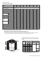
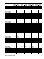
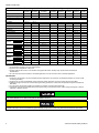
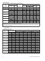
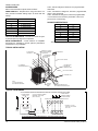
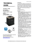
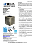
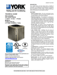
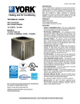
400034-YTG-B-0708
DESCRIPTION
The 13 SEER Series condensing unit is the outdoor part of a
versatile system of air conditioning. It is designed to be custom-matched with one of UPG’s complete line of evaporator
sections, with each serving a specific function. Matching Air
Handlers are available for upflow, downflow, or horizontal
applications to provide a complete system. Electric Heaters
are available, if required. Add-On coils are available for use
with upflow, downflow, or horizontal furnaces and air handlers.
WARRANTY
TECHNICAL GUIDE
Single Phase Units:
5-year limited parts warranty.
5-year limited compressor warranty.
SPLIT-SYSTEM
AIR CONDITIONERS
FEATURES
13 SEER – R-22
MODELS:
TCGD12 THRU 60
(1 THRU 5 NOMINAL TONS, 1 PHASE)
LISTED
ISO 9001
Certified Quality
Management System
Due to continuous product improvement, specifications
are subject to change without notice.
Visit us on the web at www.york.com
• QUALITY CONDENSER COILS - The coil is constructed
of aluminum microchannel tubing and enhanced aluminum
fins for increased efficiency and corrosion protection.
• PROTECTED COMPRESSOR - The compressor is internally protected against high pressure and temperature.
This is accomplished by the simultaneous operation of
high pressure relief valve and a temperature sensor which
protects the compressor if undesirable operating conditions occur. A liquid line filter-drier further protects the
compressor.
• DURABLE FINISH - The cabinet is made of pre-painted
steel. The pre-treated galvanized steel provides a better
paint to steel bond, which resists corrosion and rust creep.
Special primer formulas and matted-textured finish insure
less fading when exposed to sunlight.
• LOWER INSTALLED COST - Installation time and costs
are reduced by easy power and control wiring connections. Available in sweat connect models only. The unit
contains enough refrigerant for matching indoor coils and
15 feet of interconnecting piping. The small base dimension means less space is required on the ground or roof.
• TOP DISCHARGE - The warm air from the top mounted
fan is blown up away from the structure and any landscaping. This allows compact location on multi-unit applications.
• LOW OPERATING SOUND LEVEL - The upward air flow
carries the normal operating noise away from the living
area. The rigid top panel effectively isolates any motor
sound. Isolator mounted compressor and the rippled fins
of the condenser coil muffle the normal fan motor and
compressor operating sounds.
• LOW MAINTENANCE - Long life permanently lubricated
motor-bearings need no annual servicing.
• EASY SERVICE ACCESS - Fully exposed refrigerant connections, and a single panel covering the electrical controls make for easy servicing of the unit.
• SECURED SERVICE VALVES - Secured re-usable service valves are provided on both the liquid and vapor
sweat connections for ease of evacuating and charging.
• U.L. and C.U.L. listed - approved for outdoor application.
Certified in accordance with the Unitary Small Equipment certification program, which is based on ARI Standard 210/240.
Additional rating information can be found at
www.ahridirectory.org
FOR DISTRIBUTION USE ONLY - NOT TO BE USED AT POINT OF RETAIL SALE
400034-YTG-B-0708
Physical and Electrical Data
TCGD12
S21S2(H)
MODEL
TCGD18
S21S2(H)
TCGD24
S21S2(H)
Unit Supply Voltage
1
Max. Overcurrent Device Amps
2
Min. Overcurrent Device Amps 3
Compressor Type
TCGD60
S21S2
6.2
9.5
11.3
14.0
18.2
19.9
22.7
33.5
15
15
15
20
30
30
35
50
15
15
15
15
20
20
25
35
Scroll
Rotary
Rotary
Rotary
Recip
Recip
Recip
Recip
4.5
7.2
8.4
10.6
13.4
14.7
17.0
25.6
Locked Rotor
26.0
40.0
47.0
61.0
78.0
78.0
86.0
150.0
No
No
No
No
No
No
No
No
0.50
0.50
0.80
0.80
1.4
1.5
1.5
1.5
18
18
18
18
18
22
22
22
Rated HP
1/12
1/12
1/8
1/8
1/4
1/4
1/4
1/4
Nominal RPM
1100
1100
1075
1075
1100
850
850
850
Nominal CFM
1350
1550
1850
1950
2400
3000
3000
3300
8.1
9.7
9.7
11.3
12.1
16.5
16.5
19.75
Rated Load
Fan Diameter Inches
Face Area Sq. Ft.
Coil
TCGD48
S21S2(H)
Rated Load
Crankcase Heater
Fan Motor
TCGD42
S21S2(H)
187 to 252
Minimum Circuit Ampacity
Fan Motor Amps
TCGD36
S21S2(H)
208-230V, 1φ, 60Hz
Normal Voltage Range
Compressor Amps
TCGD30
S21S2(H)
Rows Deep
1
1
1
1
1
1
1
1
Fin / Inches
23
23
23
23
23
23
23
23
Liquid Line Set OD (Field Installed)
3/8
3/8
3/8
3/8
3/8
3/8
3/8
3/8
Vapor Line Set OD (Field Installed)
5/8
5/8
3/4
3/4
3/4
7/8
7/8
1-1/8
Unit Charge (Lbs. - Oz.) 4
3-2
3-0
3 - 13
3-7
3 - 15
4-2
4-5
5-4
Charge Per Foot, Oz.
0.66
0.66
0.68
0.68
0.68
0.70
0.70
0.76
Operating Weight Lbs.
96
110
130
150
160
175
176
200
Models with “H” on the end of the model number have a factory installed start kits.
1. Rated in accordance with ARI Standard 110, utilization range “A”.
2. Dual element fuses or HACR circuit breaker. Maximum allowable overcurrent protection.
3. Dual element fuses or HACR circuit breaker. Minimum recommended overcurrent protection.
4. The Unit Charge is correct for the outdoor unit, matched indoor coil and 15 feet of refrigerant tubing. For tubing lengths other than
15 feet, add or subtract the amount of refrigerant, using the difference in length multiplied by the per foot value.
All dimensions are in inches. They are subject to change
without notice. Certified dimensions will be provided upon
request.
C
Unit
Model
A
B
Dimensions
(Inches)
Refrigerant Connection
Service Valve Size
A1
B
C
12
24
23-1/2
23-1/2
18
28
23-1/2
23-1/2
24
28
23-1/2
23-1/2
30
32
23-1/2
23-1/2
36
34
23-1/2
23-1/2
42
34
29
29
48
34
29
29
60
40
29
29
Liquid
Vapor
3/4”
3/8”
7/8”
7/8”2
1. Including Fan Guard.
2. Expander fitting required for 1-1/8” linset.
2
Johnson Controls Unitary Products
400034-YTG-B-0708
Additional R-22 Charge / Orifice Size for Various Matched Systems
Outdoor Unit
TCGD12
S21S2(H)
TCGD18
S21S2(H)
TCGD24
S21S2(H)
TCGD30
S21S2(H)
TCGD36
S21S2(H)
TCGD42
S21S2(H)
TCGD48
S21S2(H)
TCGD60
S21S2
Required Orifice or TXV 1,2
0.041 / 2A
0.052 / 2A
0.059 / 0.061 / 2A
0.065 / 2A
0.073 / 2A
0.081 / 2C
0.084 / 2C
0.096 / 2C
Factory R-22 Charge, lbs-oz
3-2
3-0
3 - 13
3-7
3 - 15
4-2
4-5
5-4
–
Indoor Coil3,4
Additional Charge, Oz
FC/MC/PC/UC18A2A
0
0
–
–
–
–
–
FC/MC/PC/UC18B2A
0
0
–
–
–
–
–
–
FC/MC/PC/UC24A2A
–
0
–
–
–
–
–
–
FC/MC/PC/UC24B2A
–
0
–
–
–
–
–
–
FC/MC/PC32A2A
–
–
+3
+4
–
–
–
–
FC/MC/PC35B2A
–
–
+3
+4
–
–
–
–
FC/MC/PC35C2A
–
–
+3
+4
–
–
–
–
FC/MC/PC/UC36A2A
–
–
0
–
–
–
–
–
FC/MC/PC/UC36B2A
–
–
0
–
–
–
–
–
FC/MC/PC/UC36C2A
–
–
0
–
–
–
–
–
FC/MC/PC37A2A
–
–
+7
+12
+4
–
–
–
FC/MC/PC43B2C
–
–
–
–
–
0
–
–
FC/MC/PC43C2C
–
–
–
–
–
0
–
–
FC/MC/PC/UC48C2C
–
–
–
–
–
+5
+2
–
FC/MC/PC/UC48D2C
–
–
–
–
–
+5
+2
–
FC/MC62D2C
–
–
–
–
–
–
–
0
HC18A2A
0
0
–
–
–
–
–
–
HC30A2A
–
–
0
–
–
–
–
–
HC36B2A
–
–
+3
+4
–
–
–
–
HC42C2C
–
–
–
+12
+4
0
–
–
AHP18B2A
0
0
–
–
–
–
–
–
AHP24B2A
–
0
–
–
–
–
–
–
–
AHP30B2A
–
–
+3
+4
–
–
–
AHP36C2A
–
–
–
+12
+4
–
–
–
AHP42C2C
–
–
–
–
–
0
–
–
AHP/SHP60D2C
–
–
–
–
–
–
0
–
AV24B2A
–
+2
–
–
–
–
–
–
AV36C2A
–
–
+7
+12
+4
–
–
–
AV/SV48D2C
–
–
–
–
–
–
0
–
FC/MC/PC/UC18A3X
41 + 0
52 + 0
–
–
–
–
–
–
FC/MC/PC/UC18B3X
41 + 0
52 + 0
–
–
–
–
–
–
FC/MC/PC/UC24A3X
–
52 + 2
–
–
–
–
–
–
FC/MC/PC/UC24B3X
–
52 + 2
–
–
–
–
–
–
FC/MC/PC32A3X
–
–
61 + 3
65 + 4
–
–
–
–
FC/MC/PC35B3X
–
–
61 + 3
65 + 4
–
–
–
–
FC/MC/PC35C3X
–
–
61 + 3
65 + 4
–
–
–
–
FC/MC/PC/UC36A3X
–
–
59 + 0
–
–
–
–
–
FC/MC/PC/UC36B3X
–
–
59 + 0
–
–
–
–
–
FC/MC/PC/UC36C3X
–
–
59 + 0
–
–
–
–
–
FC/MC/PC37A3X
–
–
61 + 7
65 + 12
73 + 4
–
–
–
FC/MC/PC43B3X
–
–
61 + 7
65 + 12
73 + 4
81 + 0
–
–
FC/MC/PC43C3X
–
–
61 + 7
65 + 12
73 + 4
81 + 0
–
–
FC/MC/PC/UC48C3X
–
–
–
–
73 + 4
81 + 5
84 + 2
–
FC/MC/PC/UC48D3X
–
–
–
–
73 + 4
81 + 5
84 + 2
–
FC/MC62D3X
–
–
–
–
–
–
–
96 + 0
HC18A3X
41 + 0
52 + 0
–
–
–
–
–
–
HC30A3X
–
–
59 + 0
–
–
–
–
–
HC36B3X
–
–
61 + 3
65 + 4
–
–
–
–
HC42C3X
–
–
61 + 7
65 + 12
73 + 4
81 + 0
–
–
For Notes See Page 4.
Johnson Controls Unitary Products
3
400034-YTG-B-0708
Additional R-22 Charge / Orifice Size for Various Matched Systems (Continued)
Outdoor Unit
TCGD12
S21S2(H)
TCGD18
S21S2(H)
TCGD24
S21S2(H)
TCGD30
S21S2(H)
TCGD36
S21S2(H)
TCGD42
S21S2(H)
TCGD48
S21S2(H)
TCGD60
S21S2
Required Orifice or TXV 1,2
0.041 / 2A
0.052 / 2A
0.059 / 0.061 / 2A
0.065 / 2A
0.073 / 2A
0.081 / 2C
0.084 / 2C
0.096 / 2C
Factory R-22 Charge, lbs-oz
3-2
3-0
3 - 13
3-7
3 - 15
4-2
4-5
5-4
–
Indoor Coil3,4
Additional Charge, Oz
AHP18B3X
41 + 0
52 + 0
–
–
–
–
–
AHP24B3X
–
52 + 0
–
–
–
–
–
–
AHP30B3X
–
–
61 + 3
65 + 4
–
–
–
–
AHP36C3X
–
–
–
–
73 + 4
–
–
–
AHP42C3X
–
–
–
–
73 + 4
81 + 0
–
–
AHP/SHP60D3X
–
–
–
–
–
–
84 + 0
–
AV24B3X
–
52 + 2
–
–
–
–
–
–
AV36C3X
–
–
61 + 7
65 + 12
73 + 4
–
–
–
AV/SV48D3X
–
–
–
–
–
–
84 + 0
–
–
52 + 0
–
–
–
–
–
–
–
2A + 0
–
–
–
–
–
–
–
–
61 + 1
–
–
–
–
–
–
–
2A + 2
–
–
–
–
–
–
–
–
65 + 0
–
–
–
–
–
–
–
2A + 0
–
–
–
–
–
–
–
–
73 + 0
81 + 5
84 + 2
–
–
F4FP024
F4FP036
F4FP040
F5FP048
See Caution below
See Caution below
See Caution below
See Caution below
F5FP060
See Caution below
F4FV060
See Caution below
–
–
–
–
2A + 0
2C + 5
2C + 2
–
–
–
–
–
–
84 + 0
–
–
–
–
–
–
–
2C + 0
–
–
–
–
–
–
–
84 + 0
–
–
–
–
–
–
–
2C + 0
–
FOOTNOTES:
1. For applications requiring a TXV use 1TVM series kit.
2. Approved orifice shipped with outdoor unit.
3. Systems matched with furnace or air handlers not equipped with blower-off delays may require blower Time Delay Kit
2FD06700224.
4. PC coils cannot be used in downflow or horizontal applications. FC coils cannot be used in horizontal applications.
PROCEDURES:
1. Unit factory charge listed on the unit nameplate includes refrigerant for the condenser, the smallest evaporator and 15 feet of interconnecting line tubing.
2. Verify the TXV or orifice and additional charge required for specific evaporator coil in the system using the above table.
3. Additional charge for the amount of interconnecting line tubing greater than 15 feet at the rate specified in Physical and Electrical
Data Table.
4. For TXV match charge weight needs to be weighed in for specififc coil match and lineset length.
5. Permanently mark the unit nameplate with the total system charge. Total System Charge = Base Charge (as shipped) + adder for
evaporator + adder for line set.
Models 12-48 require start kits for TXV matches. Models with “H” on the end of the model number have factory installed start kits.
For models without an “H” refer to tech guide for kit number reference.
F*FP Air Handlers come with a factory installed R-22 TXV. Please note that some models may take a different TXV then what is factory
installed. The proper TXV must be installed for system reliability and performance. Also note, TXV must be removed for orifice match.
4
Johnson Controls Unitary Products
400034-YTG-B-0708
COOLING CAPACITY - With Air Handler Coils
UNIT
MODEL
AIR HANDLER
COIL
MODEL1
MODEL
W
MA08B
17
FC/MC18B
MA08B
17
FC/MC24B
MA08B
17
MA08B
COOLING
RATED
CFM
NET MBH
SEER
EER
12.6
13.00
11.00
12.6
13.00
11.00
24.0
17.2
13.00
11.00
800
24.0
17.2
13.00
11.00
FC/MC43B
800
24.0
17.2
13.00
11.00
17
FC/MC35B
1000
29.0
21.2
13.00
11.00
MA12B
17
FC/MC43B
1000
29.0
21.2
13.00
11.00
MA12B
17
FC/MC43B
1200
35.0
24.4
13.00
11.00
MA14D
24
FC/MC48D
1200
35.0
24.4
13.00
11.00
MA16C
21
FC/MC43C
1400
42.0
29.4
13.00
11.00
MA14D
24
FC/MC48D
1400
42.0
29.4
13.00
11.00
MA16C
21
FC/MC48C
1400
42.0
29.4
13.00
11.00
MA16C
21
FC/MC48C
1600
46.0
32.6
13.00
11.00
MA20D
24
FC/MC48D
1600
46.0
32.6
13.00
11.00
MA20D
24
FC/MC62D
1800
54.0
41.5
13.00
11.00
TOTAL
SENS.
600
18.0
600
18.0
FC/MC35B
800
17
FC/MC36B
MA08B
17
MA12B
13 SEER AC WITH MA
TCGD18S21S2(H)
TCGD24S21S2(H)
TCGD30S21S2(H)
TCGD36S21S2(H)
TCGD42S21S2(H)
TCGD48S21S2(H)
TCGD60S21S2
13 SEER AC WITH MV - VARIABLE SPEED
MV12B
17
FC/MC18B
600
18.0
13.0
14.00
12.00
MV12B
17
FC/MC24B
600
18.0
13.0
14.00
12.00
MV12B
17
FC/MC36B
800
24.0
17.8
14.00
12.00
MV12B
17
FC/MC35B
800
24.0
17.8
14.00
12.00
MV12B
17
FC/MC43B
800
24.0
17.8
14.00
12.00
MV12B
17
FC/MC35B
1000
30.0
21.8
14.00
12.00
MV12B
17
FC/MC43B
1000
30.0
21.8
14.00
12.00
MV16C
21
FC/MC35C
1000
30.0
21.8
14.00
12.00
MV16C
21
FC/MC43C
1000
30.0
21.8
14.00
12.00
MV16C
21
FC/MC43C
1200
36.0
25.0
14.00
12.00
MV16C
21
FC/MC48C
1200
36.0
25.2
14.00
12.00
MV20D
24
FC/MC48D
1200
36.0
25.2
14.00
12.00
MV12D
24
FC/MC48D
1135
35.0
25.2
14.00
12.00
MV16C
21
FC/MC43C
1400
42.0
30.0
14.00
12.00
MV16C
21
FC/MC48C
1400
42.0
30.0
14.00
12.00
MV20D
24
FC/MC48D
1400
42.0
30.0
14.00
12.00
MV16C
21
FC/MC48C
1600
45.0
33.2
13.50
11.00
MV20D
24
FC/MC48D
1600
46.0
33.0
13.50
11.00
TCGD60S21S2
MV20D
24
FC/MC62D
1800
55.0
41.5
13.50
11.00
TCGD18S21S2(H)
TCGD24S21S2(H)
AV24
AV36
12.00
TCGD30S21S2(H)
TCGD18S21S2(H)
TCGD24S21S2(H)
TCGD30S21S2(H)
TCGD36S21S2(H)
TCGD42S21S2(H)
TCGD48S21S2(H)
TCGD36S21S2(H)
TCGD48S21S2(H)
13 SEER AC WITH AV / SV - / F*FV VARIABLE SPEED
565
18.0
17
–
13.1
14.00
21
–
765
24.0
17.9
14.00
12.00
AV36
21
–
1015
30.0
22.0
14.00
12.00
12.00
AV36
21
–
1270
35.0
25.0
14.00
AV/SV48
24
–
1610
45.0
33.2
13.50
11.00
F4FV060
24
–
1600
45.0
33.2
13.50
11.00
For Notes See Page 6.
Johnson Controls Unitary Products
5
400034-YTG-B-0708
COOLING CAPACITY - With Air Handler Coils (Continued)
AIR HANDLER
COIL
COOLING
UNIT
MODEL
MODEL
W
TCGD12S21S2(H)
AHP18
17
–
450
12.0
AHP18
17
–
650
18.0
AHP24
17
–
650
18.0
12.6
13.00
11.00
F4FP024
18
–
600
18.0
12.6
1300
11.00
MODEL1
RATED
CFM
NET MBH
TOTAL
SEER
EER
8.9
13.00
11.00
12.6
13.00
11.00
SENS.
13 SEER AC WITH AHP / SHP / F*FP
TCGD18S21S2(H)
TCGD24S21S2(H)
TCGD30S21S2(H)
TCGD36S21S2(H)
TCGD42S21S2(H)
TCGD48S21S2(H)
AHP30
17
–
795
24.0
17.3
13.00
11.00
F4FP036
21.5
–
860
24.0
17.3
13.00
11.00
AHP30
17
–
1015
29.0
21.2
13.00
11.00
AHP36
21
–
1015
29.0
21.2
13.00
11.00
F4FP040
21.5
–
1000
29.0
21.2
13.00
11.00
AHP36
21
–
1235
35.0
24.4
13.00
11.00
F5FP048
24
–
1235
35.0
24.4
13.00
11.00
AHP42
21
–
1485
42.0
29.4
13.00
11.00
F5FP048
24
–
1455
42.0
29.4
13.00
11.00
AHP/SHP60
24
–
1600
46.0
33.0
13.00
11.00
F5FP048
24
–
1690
46.0
33.0
13.00
11.00
F5FP060
24
–
1680
46.0
33.0
13.00
11.00
Rated in accordance with DOE test procedures (Federal Register 12-27-79 and 3-18-88) and ARI Standards 210.
Cooling MBH based on 80°F entering air temperature, 50% RH, and rated air flow.
EER (Energy Efficiency Ratio) is the total cooling output in BTU’s at 95°F outdoor ambient divided by the total electric power in watt-hours at those conditions.
SEER (Seasonal Energy Efficiency Ratio) is the total cooling output in BTU’s during a normal annual usage period for cooling divided by the total electric power
input in watt-hours during the same period.
1. MC coils available with a factory installed horizontal drain pan. See price pages for specific model number.
— = Not applicable.
CONDENSER ONLY DATA
Model
TCGD12S21S2(H)
SH 11 / SC 13 @
95 OD Temp
TCGD18S21S2(H)
SH 11 / SC 10 @
95 OD Temp
TCGD24S21S2(H)
SH 10 / SC 12 @
95 OD Temp
TCGD30S21S2(H)
SH 12 / SC 10 @
95 OD Temp
TCGD36S21S2(H)
SH 10 / SC 11 @
95 OD Temp
TCGD42S21S2(H)
SH 10 / SC 9 @ 95
OD Temp
TCGD48S21S2(H)
SH 10 / SC 12 @
95 OD Temp
TCGD60S21S2
SH 10 / SC 9 @ 95
OD Temp
6
Suct. T/P @ Compr.
Temp.
40
45
50
40
45
50
40
45
50
40
45
50
40
45
50
40
45
50
40
45
50
40
45
50
PSIG
68.6
76.1
84.1
68.6
76.1
84.1
68.6
76.1
84.1
68.6
76.1
84.1
68.6
76.1
84.1
68.6
76.1
84.1
68.6
76.1
84.1
68.6
76.1
84.1
75° F
MBH
11.81
12.65
13.55
17.53
18.63
19.80
22.88
24.93
27.12
28.77
30.28
31.89
31.46
36.54
41.95
40.44
45.28
50.44
42.04
46.86
52.00
52.76
59.98
67.69
KW
0.73
0.73
0.74
1.07
1.07
1.08
1.42
1.44
1.47
1.75
1.80
1.86
2.16
2.20
2.24
2.46
2.52
2.59
2.70
2.77
2.85
3.40
3.41
3.41
Air Temp on Condenser
95° F
MBH
KW
8.15
0.85
10.15
0.86
12.29
0.87
15.03
1.29
17.25
1.30
19.61
1.31
19.07
1.70
22.25
1.72
25.63
1.75
23.85
2.01
26.56
2.07
29.45
2.13
18.41
2.37
25.84
2.47
33.77
2.58
28.86
2.83
36.10
2.91
43.82
3.00
26.14
3.03
35.10
3.16
44.65
3.30
46.38
4.04
53.35
4.14
60.79
4.25
115° F
MBH
5.29
7.21
9.26
11.98
14.07
16.30
13.99
17.25
20.72
17.06
19.76
22.64
13.42
18.88
24.71
21.78
27.55
33.70
21.19
27.59
34.43
36.26
42.46
49.07
KW
1.01
1.02
1.04
1.57
1.59
1.61
2.02
2.07
2.12
2.21
2.31
2.40
2.78
2.85
2.91
3.21
3.30
3.41
3.49
3.60
3.73
5.08
5.15
5.22
Johnson Controls Unitary Products
400034-YTG-B-0708
COOLING CAPACITY - Upflow, Downflow & Horizontal Furnaces and Coils
FURNACE**
UNIT MODEL
TCGD12S21S2(H)
TCGD18S21S2(H)
TCGD24S21S2(H)
TCGD30S21S2(H)
TCGD36S21S2(H)
TCGD42S21S2(H)
TCGD48S21S2(H)
TCGD60S21S2
COOLING
CFM RANGE
(Min.-max.)
W
COIL
MODEL
450 - 750
14,17
450 - 750
14
450 - 750
NET MBH
RATED
CFM
TOTAL
SENS.
FC/MC/PC18
450
12.0
HC18
450
12.0
14,17
UC18
450
450 - 750
14,17
FC/MC/PC18
450 - 750
14,17
FC/MC/PC24
450 - 750
14
450 - 750
14,17
450 - 750
14,17
UC24
600
18.0
12.6
13.00
11.00
600 - 1000
14
FC/MC/PC32
800
24.0
17.2
13.00
11.00
SEER1
EER
9.1
13.00
11.00
9.1
13.00
11.00
12.0
9.1
13.00
11.00
600
18.0
12.6
13.00
11.00
600
18.0
12.6
13.00
11.00
HC18
600
18.0
12.6
13.00
11.00
UC18
600
18.0
12.6
13.00
11.00
600 - 1000
17,21
FC/MC/PC35
800
24.0
17.2
13.00
11.00
600 - 1000
14,17,21
FC/MC/PC36
800
24.0
17.2
13.00
11.00
600 - 1000
14
FC/MC/PC37
800
24.0
17.2
13.00
11.00
600 - 1000
17,21
FC/MC/PC43
800
24.0
17.2
13.00
11.00
600 - 1000
14
HC30
800
24.0
17.2
13.00
11.00
600 - 1000
17
HC36
800
24.0
17.2
13.00
11.00
600 - 1000
21
HC42
800
24.0
17.2
13.00
11.00
600 - 1000
14,17,21
UC36
800
24.0
17.2
13.00
11.00
800 - 1200
14
FC/MC/PC32
1000
29.0
21.2
13.00
11.00
800 - 1200
17,21
FC/MC/PC35
1000
29.0
21.2
13.00
11.00
800 - 1200
14
FC/MC/PC37
1000
29.0
21.2
13.00
11.00
800 - 1200
17,21
FC/MC/PC43
1000
29.0
21.2
13.00
11.00
800 - 1200
17
HC36
1000
29.0
21.2
13.00
11.00
800 - 1200
21
HC42
1000
29.0
21.2
13.00
11.00
1000 - 1400
14
FC/MC/PC37
1200
35.0
24.4
13.00
11.00
1000 - 1400
17,21
FC/MC/PC43
1200
35.0
24.4
13.00
11.00
1000 - 1400
21,24
FC/MC/PC48
1200
35.0
24.4
13.00
11.00
1000 - 1400
21
HC42
1200
35.0
24.4
13.00
11.00
1000 - 1400
21,24
UC48
1200
35.0
24.4
13.00
11.00
1200 - 1600
17,21
FC/MC/PC43
1400
42.0
29.4
13.00
11.00
1200 - 1600
21,24
FC/MC/PC48
1400
42.0
29.4
13.00
11.00
1200 - 1600
21
HC42
1400
42.0
29.4
13.00
11.00
1200 - 1600
21,24
UC48
1400
42.0
29.4
13.00
11.00
1400 - 1800
21,24
FC/MC/PC48
1550
46.0
32.6
13.00
11.00
1400 - 1800
21,24
UC48
1550
46.0
32.6
13.00
11.00
1600 - 2000
24
FC/MC62
2000
55.0
41.0
13.00
11.00
1. Requires a 2FD06700224 Blower Time Delay unless a standard furnace is equipped with one.
** Refer to Quick Selection Chart for specific furnace match-up.
Johnson Controls Unitary Products
7
400034-YTG-B-0708
1
COOLING CAPACITY - With Variable Speed Furnaces
UNIT MODEL
VARIABLE SPEED
FURNACE MODEL
COIL
MODEL1
COOLING
W
RATED
CFM
Net MBH
TOTAL
SENS.
SEER
EER
13 SEER AC WITH VARIABLE SPEED FURNACES2
TCGD18S21S2(H)
TCGD24S21S2(H)
TCGD30S21S2(H)
PV8*A12
FC/MC/PC18A
14
600
18.0
13.0
14.00
12.00
PV9*A12
FC/MC/PC18A
14
600
18.0
12.9
14.00
12.00
P(C,V)9*B12
FC/MC/PC18B
17
600
18.0
13.0
14.00
12.00
PV8*A12
FC/MC/PC24A
14
600
18.0
13.0
14.00
12.00
12.00
PV9*A12
FC/MC/PC24A
14
600
18.0
12.9
14.00
P(C,V)9*B12
FC/MC/PC24B
17
600
18.0
13.0
14.00
12.00
PV8*A12
HC18
14
600
18.0
13.0
14.00
12.00
PV9*A12
HC18
14
600
18.0
12.9
14.00
12.00
PV8*A12
FC/MC/PC32A
14
800
24.0
17.7
14.00
12.00
PV9*A12
FC/MC/PC32A
14
800
24.0
17.7
14.00
12.00
P(C,V)9*B12
FC/MC/PC35B
17
800
24.0
17.7
14.00
12.00
PV8*A12
FC/MC/PC36A
14
800
24.0
17.7
14.00
12.00
PV9*A12
FC/MC/PC36A
14
800
24.0
17.7
14.00
12.00
P(C,V)9*B12
FC/MC/PC36B
17
800
24.0
17.7
14.00
12.00
PV8*A12
FC/MC/PC37A
14
800
24.0
17.7
14.00
12.00
12.00
PV9*A12
FC/MC/PC37A
14
800
24.0
17.7
14.00
P(C,V)9*B12
FC/MC/PC43B
17
800
24.0
17.7
14.00
12.00
PV8*A12
HC30
14
800
24.0
17.7
14.00
12.00
12.00
PV9*A12
HC30
14
800
24.0
17.7
14.00
P(C,V)9*B12
HC36
17
800
24.0
17.7
14.00
12.00
PV8*A12
FC/MC/PC32A
14
1000
30.0
21.8
14.00
12.00
PV9*A12
FC/MC/PC32A
14
1000
30.0
21.8
14.00
12.00
PV8*B16
FC/MC/PC35B
17
1000
30.0
21.8
14.00
12.00
PV8*C16
FC/MC/PC35C
21
1000
30.0
21.8
14.00
12.00
PV8*C20
FC/MC/PC35C
21
1000
30.0
22.0
14.00
12.00
P(C,V)9*B12
FC/MC/PC35B
17
1000
30.0
21.6
14.00
12.00
PV8*A12
FC/MC/PC37A
14
1000
30.0
21.8
14.00
12.00
PV9*A12
FC/MC/PC37A
14
1000
30.0
21.8
14.00
12.00
PV8*B16
FC/MC/PC43B
17
1000
30.0
21.8
14.00
12.00
PV8*C16
FC/MC/PC43C
21
1000
30.0
21.8
14.00
12.00
PV8*C20
FC/MC/PC43C
21
1000
30.0
22.0
14.00
12.00
P(C,V)9*B12
FC/MC/PC43B
17
1000
30.0
21.6
14.00
12.00
12.00
PV8*B16
HC36
17
1000
30.0
21.8
14.00
P(C,V)9*B12
HC36
17
1000
30.0
21.6
14.00
12.00
PV8*C16
HC42
21
1000
30.0
22.0
14.00
12.00
PV8*C20
HC42
21
1000
30.0
22.0
14.00
12.00
P(C,V)9*C16
HC42
21
1000
30.0
22.0
14.00
12.00
For Notes See Page 8.
8
Johnson Controls Unitary Products
400034-YTG-B-0708
COOLING CAPACITY - With Variable Speed Furnaces (Continued)
UNIT MODEL
VARIABLE SPEED
FURNACE MODEL
COIL
MODEL1
COOLING
W
RATED
CFM
Net MBH
TOTAL
SENS.
SEER
EER
13 SEER AC WITH VARIABLE SPEED FURNACES2
TCGD36S21S2(H)
TCGD42S21S2(H)
TCGD48S21S2(H)
TCGD60S21S2
PV8*A12
FC/MC/PC37A
14
1200
35.2
25.0
14.00
12.00
PV9*A12
FC/MC/PC37A
14
1200
35.2
25.0
14.00
12.00
PV8*B16
FC/MC/PC43B
17
1200
35.4
25.0
14.00
12.00
PV8*C16
FC/MC/PC43C
21
1200
35.4
25.0
14.00
12.00
PV8*C20
FC/MC/PC43C
21
1200
35.6
25.0
14.00
12.00
P(C,V)9*B12
FC/MC/PC43B
17
1200
35.2
24.8
13.50
11.00
P(C,V)9*C16
FC/MC/PC43C
21
1200
35.4
25.0
13.50
11.00
P(C,V)9*C20
FC/MC/PC43C
21
1200
35.4
25.0
14.00
12.00
PV8*C16
FC/MC/PC48C
21
1200
35.6
25.0
14.00
12.00
PV8*C20
FC/MC/PC48C
21
1200
35.6
25.0
14.00
12.00
P(C,V)9*C16
FC/MC/PC48C
21
1200
35.4
25.0
14.00
12.00
P(C,V)9*C20
FC/MC/PC48C
21
1200
35.4
25.0
14.00
12.00
P(C,V)9*D20
FC/MC/PC48D
24
1200
35.4
25.0
14.00
12.00
PV8*C16
HC42
21
1200
36.0
25.0
14.00
12.00
PV8*C20
HC42
21
1200
36.0
25.0
14.00
12.00
P(C,V)9*C16
HC42
21
1200
35.0
25.0
14.00
12.00
P(C,V)9*C20
HC42
21
1200
35.0
25.0
14.00
12.00
PV8*C20
FC/MC/PC43C
21
1400
41.0
29.8
13.50
11.00
PV8*C16
FC/MC/PC48C
21
1400
42.0
29.8
13.50
11.00
PV8*C20
FC/MC/PC48C
21
1400
41.0
30.0
13.50
11.00
P(C,V)9*C16
FC/MC/PC48C
21
1400
42.0
29.8
13.50
11.00
P(C,V)9*C20
FC/MC/PC48C
21
1400
42.0
29.8
13.50
11.00
P(C,V)9*D20
FC/MC/PC48D
24
1400
42.0
29.8
13.50
11.00
PV8*C16
HC42
21
1400
42.0
29.8
13.50
11.00
PV8*C20
HC42
21
1400
41.0
30.0
13.50
11.00
P(C,V)9*C16
HC42
21
1400
42.0
29.6
13.50
11.00
P(C,V)9*C20
HC42
21
1400
41.0
29.8
13.50
11.00
PV8*C16
FC/MC/PC48C
21
1500
46.0
32.8
13.25
11.00
PV8*C20
FC/MC/PC48C
21
1600
46.0
32.8
13.30
11.00
P(C,V)9*C16
FC/MC/PC48C
21
1600
46.0
32.6
13.10
11.00
P(C,V)9*C20
FC/MC/PC48C
21
1600
46.0
32.8
13.10
11.00
P(C,V)9*D20
FC/MC/PC48D
24
1600
46.0
32.8
13.35
11.00
P V8*C20
FC/MC62D
21
1730
54.0
41.5
13.15
11.00
P(C,V)9*C20
FC/MC62D
21
1620
54.0
41.5
13.15
11.00
P(C,V)9*D20
FC/MC62D
24
1620
54.0
42.0
13.40
11.00
1. MC coils available with a factory installed horizontal drain pan. See price pages for specific model number.
2. Variable speed furnaces have B.O.D (Blower on Delay) standard.
Johnson Controls Unitary Products
9
400034-YTG-B-0708
ACCESSORIES
1H/1C, manual changeover electronic non-programmable
thermostat.
1H/1C, auto/manual changeover, electronic programmable,
deluxe 7-day, thermostat.
1H/1C, auto/manual changeover, electronic programmable.
* For the most current accessory information, refer to the
price book or consult factory.
Refer to Price Manual for specific model numbers.
HARD START KIT - Required when using TXV indoor coil.
Also, provides increased starting torque for areas with low
voltage.
Model
Source 1 Kit numbers
12
S1-2SA06708606
18
S1-2SA06708606
24
S1-2SA06708706
30
S1-2SA06705906
36
S1-2SA06708106
42
S1-2SA06708106
48
S1-2SA06708806
SOUND POWER RATINGS*
UNIT MODEL
12
18
24
30
36
42
48
60
OFF CYCLE TIMER DELAY - Provides a 5-minute off cycle
to prevent rapid recycling of the compressor.
ROOM THERMOSTATS - A wide selection of compatible
thermosets are available to provide optimum performance
and features for any installation.
(dBA)
72
75
76
75
76
75
76
78
* Rated in accordance with ARI 270-95 Standards.
TYPICAL INSTALLATION
60” OVERHEAD
CLEARANCE
MINIMUM 18” SERVICE
ACCESS CLEARANCE
ON ONE SIDE
THERMOSTAT
WEATHERPROOF
DISCONNECT
SWITCH
NEC CLASS 1 WIRING
6” CLEARANCE
AROUND PERIMETER
TO FURNACE OR
AIR HANDLER
TERMINAL BLOCK
NEC CLASS 2 WIRING
TO INDOOR COIL
NOTE:
ALL OUTDOOR WIRING
MUST BE WEATHERPROOF.
CONTROL
ACCESS
PANEL
SEAL OPENING(S) WITH
PERMAGUM OR EQUIVALENT
TYPICAL FIELD WIRING
ALL FIELD WIRING TO BE IN ACCORDANCE WITH ELECTRIC CODE (NEC) AND/OR LOCAL CODES
POWER WIRING
208/230-1-60
POWER WIRING
CONTROL WIRING
FACTORY WIRING
24 VOLT CONTROL WIRING
MINIMUM 18 GA. WIRE
(NEC CLASS 2)
FURNACE OR AIR HANDLER TERMINAL BLOCK
C
Y
R
G
W
* TERMINAL W IS ONLY
REQUIRED ON SYSTEMS
WITH HEAT.
CONTACTOR
TERMINALS
GND.
LUG
COIL
CONDENSING UNIT
Y
R
G
W
*
ROOM THERMOSTAT
ALL OUTDOOR WIRING MUST BE WEATHERPROOF. USE COPPER CONDUCTORS ONLY.
10
Johnson Controls Unitary Products
400034-YTG-B-0708
COOLING PERFORMANCE DATA
AIR CONDITIONER MODEL NO.
INDOOR COIL MODEL NO.
IDCFM
CONDENSING
ENTERING AIR
ID DB (°F)
TEMPERATURE
ID WB (°F)
T.C.
65
S.C.
KW
T.C.
75
S.C.
KW
T.C.
85
S.C.
KW
T.C.
95
S.C.
KW
T.C.
105
S.C.
KW
T.C.
115
S.C.
KW
T.C.
125
S.C.
KW
TCGD12S21S2(H)
FC/MC/PC18
450
80
80
75
57
62
62
11.3 11.9 12.1
11.1 10.2 9.1
0.7
0.7
0.7
11.1 11.7 11.7
10.9 10.4 9.1
0.7
0.7
0.7
10.9 11.6 11.4
10.7 10.6 9.0
0.8
0.8
0.8
10.7 11.5 11.1
10.5 10.8 9.0
0.9
0.9
0.9
10.0 10.9 10.2
9.8 10.3 8.6
1.0
1.0
1.0
9.3 10.3 9.3
9.2
9.9
8.2
1.1
1.0
1.1
8.6
9.7
8.4
8.5
9.4
7.8
1.1
1.1
1.1
80
67
13.1
9.0
0.7
12.9
9.0
0.7
12.6
9.0
0.8
12.3
9.0
0.9
11.5
8.8
1.0
10.7
8.6
1.1
9.9
8.4
1.2
600
80
80
80
75
80
80
80
80
72
57
62
62
67
72
57
62
14.1 11.7 12.4 12.3 13.2 14.1 12.1 12.9
7.2 11.5 11.0 9.6
9.2
7.4 11.9 11.8
0.7
0.7
0.7
0.7
0.7
0.7
0.7
0.7
13.8 11.6 12.2 12.0 13.0 13.8 12.0 12.7
7.2 11.4 11.2 9.6
9.4
7.4 11.8 11.9
0.7
0.7
0.7
0.7
0.7
0.7
0.7
0.7
13.5 11.4 12.1 11.7 12.8 13.6 11.9 12.6
7.1 11.2 11.3 9.6
9.6
7.5 11.7 12.1
0.8
0.8
0.8
0.8
0.8
0.8
0.8
0.8
13.2 11.2 12.0 11.3 12.6 13.3 11.7 12.4
7.1 11.0 11.5 9.7
9.7
7.5 11.5 12.2
0.9
0.9
0.9
0.9
0.9
0.9
0.9
0.9
12.5 10.6 11.4 10.5 11.8 12.7 11.1 11.9
6.9 10.4 10.9 9.2
9.5
7.3 11.0 11.5
1.0
1.0
1.0
1.0
1.0
1.0
1.0
1.0
11.9 9.9 10.9 9.7 11.0 12.2 10.5 11.4
6.7
9.8 10.3 8.8
9.3
7.2 10.4 10.8
1.1
1.1
1.1
1.1
1.1
1.1
1.1
1.1
11.2 9.3 10.3 8.9 10.2 11.6 9.9 10.9
6.5
9.2
9.8
8.4
9.1
7.0
9.8 10.1
1.2
1.2
1.1
1.1
1.2
1.2
1.2
1.2
750
75
62
12.6
10.0
0.7
12.3
10.1
0.7
11.9
10.3
0.8
11.6
10.4
0.9
10.9
9.9
1.0
10.1
9.4
1.1
9.4
8.9
1.1
80
67
13.2
9.5
0.7
13.1
9.8
0.7
13.0
10.1
0.8
12.8
10.4
0.9
12.0
10.2
1.0
11.3
10.0
1.1
10.5
9.8
1.2
80
72
14.1
7.5
0.7
13.9
7.7
0.7
13.7
7.8
0.8
13.4
7.9
0.9
12.9
7.8
1.0
12.4
7.6
1.1
11.9
7.5
1.2
NOTE: ALL CAPACITIES INCLUDE INDOOR FAN HEAT AT 1250 BTUH/1000 CFM.
Multipliers for determining the performance with other indoor sections.
NOTE: For dry bulb temperatures different than those listed (between 73-87 F), sensible capacity increases by 1060 BTUH per 1000 CFM per degree above the
listed temperature and decreases by 1060 BTUH per 1000 CFM per degree below the listed temperature.
Air Handler
–
–
AHP18
Coil
HC18
UC18
–
Johnson Controls Unitary Products
T.C.
1.00
1.00
0.98
S.C.
1.00
1.00
0.97
KW
1.00
1.00
0.98
11
400034-YTG-B-0708
COOLING PERFORMANCE DATA
AIR CONDITIONER MODEL NO.
INDOOR COIL MODEL NO.
IDCFM
CONDENSING
ENTERING AIR
ID DB (°F)
TEMPERATURE
ID WB (°F)
T.C.
65
S.C.
KW
T.C.
75
S.C.
KW
T.C.
85
S.C.
KW
T.C.
95
S.C.
KW
T.C.
105
S.C.
KW
T.C.
115
S.C.
KW
T.C.
125
S.C.
KW
TCGD18S21S2(H)
FC/MC/PC18
450
80
80
75
57
62
62
15.4 17.1 16.7
15.2 13.4 11.4
1.0
1.0
1.0
14.9 16.6 16.3
14.7 13.4 11.3
1.1
1.1
1.1
14.4 16.1 15.8
14.3 13.5 11.2
1.2
1.2
1.2
13.9 15.7 15.4
13.8 13.5 11.1
1.3
1.3
1.3
13.2 14.6 14.2
13.1 13.1 10.6
1.5
1.5
1.5
12.5 13.6 13.1
12.4 12.6 10.1
1.6
1.6
1.6
11.8 12.6 12.0
11.7 12.2 9.6
1.7
1.7
1.7
80
67
18.1
11.3
1.0
17.7
11.1
1.1
17.3
11.0
1.2
16.8
10.8
1.3
15.9
10.6
1.5
15.0
10.3
1.6
14.2
10.1
1.8
80
72
18.0
8.6
1.0
18.0
8.5
1.1
18.0
8.5
1.2
17.9
8.5
1.3
17.2
8.3
1.5
16.5
8.1
1.6
15.7
7.9
1.8
80
57
16.2
16.0
1.0
15.9
15.7
1.1
15.6
15.5
1.2
15.3
15.2
1.3
14.6
14.4
1.5
13.9
13.7
1.6
13.2
13.0
1.8
80
62
17.6
14.7
1.0
17.3
14.9
1.1
17.0
15.2
1.2
16.6
15.4
1.3
15.7
14.8
1.5
14.9
14.1
1.6
14.1
13.5
1.8
600
75
62
17.2
12.6
1.0
16.8
12.7
1.1
16.3
12.8
1.2
15.9
12.9
1.3
14.9
12.4
1.5
13.8
11.9
1.6
12.8
11.5
1.8
80
67
18.2
12.0
1.0
17.9
12.1
1.1
17.7
12.3
1.2
17.4
12.4
1.3
16.5
12.3
1.5
15.6
12.1
1.6
14.8
11.9
1.8
80
72
18.0
9.0
1.0
18.1
9.2
1.1
18.2
9.3
1.2
18.2
9.5
1.3
17.5
9.3
1.5
16.8
9.2
1.6
16.1
9.0
1.8
80
57
17.0
16.8
1.0
16.9
16.7
1.1
16.8
16.6
1.2
16.7
16.5
1.3
16.0
15.8
1.5
15.2
15.1
1.6
14.5
14.4
1.8
80
62
18.2
16.0
1.0
18.0
16.4
1.1
17.8
16.9
1.2
17.5
17.3
1.3
16.8
16.4
1.5
16.2
15.7
1.6
15.5
14.9
1.8
750
75
62
17.6
13.8
1.0
17.3
14.1
1.1
16.9
14.4
1.2
16.5
14.7
1.3
15.5
14.2
1.5
14.6
13.7
1.6
13.6
13.3
1.8
80
67
18.3
12.7
1.0
18.2
13.1
1.1
18.1
13.6
1.2
18.0
14.0
1.3
17.1
13.9
1.5
16.2
13.8
1.6
15.3
13.8
1.8
80
72
18.0
9.5
1.0
18.2
9.8
1.1
18.4
10.2
1.2
18.5
10.5
1.3
17.8
10.4
1.5
17.2
10.2
1.6
16.5
10.1
1.8
NOTE: ALL CAPACITIES INCLUDE INDOOR FAN HEAT AT 1250 BTUH/1000 CFM.
Multipliers for determining the performance with other indoor sections.
NOTE: For dry bulb temperatures different than those listed (between 73-87 F), sensible capacity increases by 1060 BTUH per 1000 CFM per degree above the
listed temperature and decreases by 1060 BTUH per 1000 CFM per degree below the listed temperature.
Air Handler
–
–
–
AHP18
AHP24
AV24
F4FP024
MA08B
MA08B
MV12B
MV12B
12
Coil
FC/MC/PC/UC24
HC18
UC18
–
–
–
–
FC/MC18B
FC/MC24B
FC/MC18B
FC/MC24B
T.C.
1.00
1.00
1.00
1.00
1.00
1.00
1.00
1.00
1.00
1.00
1.00
S.C.
1.00
1.00
1.00
1.00
1.00
1.03
1.00
1.00
1.00
1.03
1.03
KW
1.00
1.00
1.00
1.00
1.00
0.91
1.00
1.00
1.00
0.91
0.91
Variable Speed
Furnace
PV8*A12
PV9*A12
P(C,V)9*B12
PV8*A12
PV9*A12
P(C,V)9*B12
PV8*A12
PV9*A12
Coil
T.C.
S.C.
KW
FC/MC/PC18A
FC/MC/PC18A
FC/MC/PC18B
FC/MC/PC24A
FC/MC/PC24A
FC/MC/PC24B
HC18
HC18
1.00
1.00
1.00
1.00
1.00
1.00
1.00
1.00
1.03
1.02
1.03
1.03
1.02
1.03
1.03
1.02
0.91
0.91
0.91
0.91
0.91
0.91
0.91
0.91
Johnson Controls Unitary Products
400034-YTG-B-0708
COOLING PERFORMANCE DATA
AIR CONDITIONER MODEL NO.
INDOOR COIL MODEL NO.
IDCFM
CONDENSING
ENTERING AIR
ID DB (°F)
TEMPERATURE
ID WB (°F)
T.C.
75
S.C.
KW
T.C.
85
S.C.
KW
T.C.
95
S.C.
KW
T.C.
105
S.C.
KW
T.C.
115
S.C.
KW
T.C.
125
S.C.
KW
TCGD24S21S2(H)
FC/MC/PC36
600
80
80
75
57
62
62
21.5 24.0 23.5
21.3 19.0 16.1
1.3
1.3
1.3
20.6 23.0 22.5
20.4 18.7 15.7
1.4
1.4
1.4
19.7 22.0 21.4
19.5 18.3 15.3
1.6
1.6
1.6
18.8 21.0 20.4
18.6 18.0 14.9
1.7
1.7
1.7
17.9 19.5 18.8
17.8 17.4 14.2
1.9
1.9
1.9
17.1 18.2 17.3
16.9 16.7 13.5
2.1
2.1
2.1
80
67
25.4
15.7
1.3
24.7
15.5
1.4
23.9
15.3
1.6
23.2
15.1
1.7
21.7
14.6
1.9
20.2
14.0
2.1
80
72
26.2
12.2
1.3
26.0
12.1
1.5
25.7
12.0
1.6
25.5
11.9
1.8
24.0
11.5
2.0
22.5
11.1
2.2
80
57
22.7
22.5
1.3
22.1
21.9
1.4
21.4
21.2
1.6
20.8
20.6
1.7
19.8
19.7
1.9
18.9
18.8
2.1
80
62
24.9
21.5
1.3
24.1
21.4
1.4
23.3
21.2
1.6
22.5
21.0
1.7
21.2
19.9
1.9
20.0
18.9
2.1
800
75
62
24.2
17.8
1.3
23.3
17.6
1.4
22.4
17.5
1.6
21.4
17.3
1.7
19.9
16.6
1.9
18.4
16.0
2.1
80
67
25.8
17.3
1.3
25.3
17.3
1.5
24.7
17.3
1.6
24.2
17.3
1.8
22.6
16.9
2.0
21.1
16.4
2.1
80
72
26.4
12.9
1.3
26.3
13.0
1.5
26.1
13.1
1.6
26.0
13.2
1.8
24.5
12.9
2.0
23.1
12.6
2.2
80
57
23.9
23.7
1.3
23.5
23.3
1.4
23.2
22.9
1.6
22.8
22.6
1.8
21.7
21.6
2.0
20.8
20.6
2.2
80
62
25.8
24.1
1.3
25.2
24.0
1.4
24.7
24.0
1.6
24.1
24.0
1.7
22.9
22.5
2.0
21.8
21.0
2.2
1000
75
62
24.9
19.5
1.3
24.1
19.5
1.4
23.3
19.6
1.6
22.5
19.7
1.7
21.0
19.1
1.9
19.5
18.5
2.1
80
67
26.2
18.9
1.3
25.8
19.1
1.5
25.5
19.4
1.6
25.2
19.6
1.8
23.6
19.2
2.0
22.0
18.8
2.2
80
72
26.7
13.6
1.3
26.6
13.9
1.5
26.5
14.2
1.6
26.4
14.5
1.8
25.0
14.4
2.0
23.6
14.2
2.2
NOTE: ALL CAPACITIES INCLUDE INDOOR FAN HEAT AT 1250 BTUH/1000 CFM.
Multipliers for determining the performance with other indoor sections.
NOTE: For dry bulb temperatures different than those listed (between 73-87 F), sensible capacity increases by 1060 BTUH per 1000 CFM per degree above the
listed temperature and decreases by 1060 BTUH per 1000 CFM per degree below the listed temperature.
Air Handler
–
–
–
–
–
–
–
–
AHP30
AV36
F4FP036
MA08B
MA08B
MA08B
MV12B
MV12B
MV12B
Coil
FC/MC/PC32
FC/MC/PC35
FC/MC/PC37
FC/MC/PC43
HC30
HC36
HC42
UC36
–
–
–
FC/MC35B
FC/MC36B
FC/MC43B
FC/MC36B
FC/MC43B
FC/MC35B
Johnson Controls Unitary Products
T.C.
1.00
1.00
1.00
1.00
1.00
1.00
1.00
1.00
1.00
1.00
1.00
1.00
1.00
1.00
1.00
1.00
1.00
S.C.
1.00
1.00
1.00
1.00
1.00
1.00
1.00
1.00
1.00
1.04
1.00
1.00
1.00
1.00
1.03
1.03
1.03
KW
1.00
1.00
1.00
1.00
1.00
1.00
1.00
1.00
1.00
0.88
1.00
1.00
1.00
1.00
0.88
0.88
0.88
Variable Speed
Furnace
PV8*A12
PV9*A12
P(C,V)9*B12
PV8*A12
PV9*A12
P(C,V)9*B12
PV8*A12
PV9*A12
P(C,V)9*B12
PV8*A12
PV9*A12
P(C,V)9*B12
Coil
T.C.
S.C.
KW
FC/MC/PC32A
FC/MC/PC32A
FC/MC/PC35B
FC/MC/PC36A
FC/MC/PC36A
FC/MC/PC36B
FC/MC/PC37A
FC/MC/PC37A
FC/MC/PC43B
HC30
HC30
HC36
1.00
1.00
1.00
1.00
1.00
1.00
1.00
1.00
1.00
1.00
1.00
1.00
1.02
1.02
1.02
1.02
1.02
1.02
1.02
1.02
1.02
1.02
1.02
1.02
0.88
0.88
0.88
0.88
0.88
0.88
0.88
0.88
0.88
0.88
0.88
0.88
13
400034-YTG-B-0708
COOLING PERFORMANCE DATA
AIR CONDITIONER MODEL NO.
INDOOR COIL MODEL NO.
IDCFM
CONDENSING
ENTERING AIR
ID DB (°F)
TEMPERATURE
ID WB (°F)
T.C.
65
S.C.
KW
T.C.
75
S.C.
KW
T.C.
85
S.C.
KW
T.C.
95
S.C.
KW
T.C.
105
S.C.
KW
T.C.
115
S.C.
KW
T.C.
125
S.C.
KW
TCGD30S21S2(H)
FC/MC/PC35
800
80
80
75
57
62
62
27.8 29.9 29.6
27.2 24.5 20.5
1.6
1.6
1.6
26.2 28.2 27.9
25.7 23.9 20.0
1.8
1.8
1.8
24.6 26.5 26.1
24.1 23.3 19.4
1.9
1.9
1.9
23.0 24.9 24.4
22.6 22.8 18.9
2.1
2.1
2.1
21.5 23.1 22.1
21.2 21.3 17.9
2.3
2.3
2.2
20.1 21.4 19.8
19.8 19.9 16.9
2.4
2.4
2.4
18.7 19.7 17.6
18.4 18.6 15.9
2.6
2.6
2.5
80
67
30.6
19.0
1.6
29.7
19.1
1.8
28.8
19.2
2.0
28.0
19.3
2.1
25.6
18.5
2.3
23.2
17.7
2.5
20.9
16.8
2.6
80
72
31.8
14.8
1.6
31.2
14.9
1.8
30.5
14.9
2.0
29.8
15.0
2.2
27.7
14.3
2.4
25.5
13.7
2.5
23.4
13.1
2.7
80
57
29.2
28.2
1.6
28.0
27.0
1.8
26.9
25.8
1.9
25.7
24.6
2.1
24.1
23.0
2.3
22.5
21.4
2.5
20.9
19.9
2.6
80
62
30.1
26.1
1.6
28.9
25.8
1.8
27.6
25.4
1.9
26.3
25.1
2.1
24.5
23.4
2.3
22.9
21.8
2.5
21.2
20.1
2.6
1000
75
62
29.7
21.6
1.6
28.2
21.5
1.8
26.7
21.4
1.9
25.3
21.3
2.1
23.0
20.0
2.3
20.8
18.7
2.4
18.6
17.5
2.6
80
67
30.8
20.0
1.6
30.0
20.5
1.8
29.2
20.9
2.0
28.4
21.4
2.1
26.0
20.6
2.3
23.7
19.8
2.5
21.4
19.0
2.7
80
72
31.8
15.4
1.6
31.2
15.7
1.8
30.6
16.0
2.0
29.9
16.3
2.2
28.0
15.8
2.4
26.0
15.2
2.6
24.1
14.7
2.7
80
57
30.6
29.1
1.6
29.9
28.3
1.8
29.2
27.4
2.0
28.4
26.6
2.1
26.6
24.8
2.3
24.9
23.1
2.5
23.1
21.4
2.7
80
62
30.4
27.7
1.6
29.5
27.6
1.8
28.6
27.5
2.0
27.7
27.5
2.1
26.0
25.5
2.3
24.3
23.6
2.5
22.7
21.7
2.7
1200
75
62
29.8
22.6
1.6
28.6
22.9
1.8
27.3
23.3
1.9
26.1
23.7
2.1
23.9
22.1
2.3
21.8
20.6
2.5
19.7
19.1
2.6
80
67
31.1
21.0
1.6
30.3
21.8
1.8
29.5
22.7
2.0
28.7
23.5
2.1
26.4
22.7
2.3
24.1
22.0
2.5
21.9
21.3
2.7
80
72
31.8
15.9
1.7
31.2
16.5
1.8
30.6
17.1
2.0
30.0
17.7
2.2
28.3
17.2
2.4
26.5
16.8
2.6
24.8
16.4
2.8
NOTE: ALL CAPACITIES INCLUDE INDOOR FAN HEAT AT 1250 BTUH/1000 CFM.
Multipliers for determining the performance with other indoor sections.
NOTE: For dry bulb temperatures different than those listed (between 73-87 F), sensible capacity increases by 1060 BTUH per 1000 CFM per degree above the
listed temperature and decreases by 1060 BTUH per 1000 CFM per degree below the listed temperature.
Air Handler
–
–
–
–
–
AHP30
AHP36
AV36
F4FP040
MA12B
MA12B
MV12B
MV16C
MV12B
MV16C
14
Coil
FC/MC/PC32
FC/MC/PC37
FC/MC/PC43
HC36
HC42
–
–
–
–
FC/MC35B
FC/MC43B
FC/MC43B
FC/MC43C
FC/MC35B
FC/MC35C
T.C.
1.00
1.00
1.00
1.00
1.00
1.00
1.00
1.02
1.00
1.00
1.00
1.02
1.02
1.02
1.02
S.C.
1.00
1.00
1.00
1.00
1.00
1.00
1.00
1.03
1.00
1.00
1.00
1.02
1.02
1.02
1.02
KW
1.00
1.00
1.00
1.00
1.00
1.00
1.00
0.89
1.00
1.00
1.00
0.89
0.89
0.89
0.89
Variable Speed
Furnace
PV8*A12
PV9*A12
PV8*B16
PV8*C16
PV8*C20
P(C,V)9*B12
PV9*A12
PV8*A12
PV9*A12
PV8*B16
PV8*C16
PV8*C20
P(C,V)9*B12
P(C,V)9*C16
P(C,V)9*C20
PV8*B16
P(C,V)9*B12
PV8*C16
PV8*C20
P(C,V)9*C16
P(C,V)9*C20
Coil
T.C.
S.C.
KW
FC/MC/PC32A
FC/MC/PC32A
FC/MC/PC35B
FC/MC/PC35C
FC/MC/PC35B
FC/MC/PC35C
FC/MC/PC35A
FC/MC/PC37A
FC/MC/PC37A
FC/MC/PC43B
FC/MC/PC43C
FC/MC/PC43C
FC/MC/PC43B
FC/MC/PC43C
FC/MC/PC43C
HC36
HC36
HC42
HC42
HC42
HC42
1.00
1.00
1.02
1.02
1.02
1.02
1.00
1.02
1.02
1.02
1.02
1.02
1.02
1.02
1.02
1.02
1.02
1.02
1.02
1.02
1.02
1.00
1.00
1.02
1.02
1.03
1.01
1.00
1.02
1.02
1.02
1.02
1.03
1.01
1.01
1.01
1.02
1.01
1.03
1.03
1.01
1.01
0.91
0.91
0.89
0.89
0.89
0.89
0.91
0.89
0.89
0.89
0.89
0.89
0.89
0.89
0.89
0.89
0.89
0.89
0.89
0.89
0.89
Johnson Controls Unitary Products
400034-YTG-B-0708
COOLING PERFORMANCE DATA
AIR CONDITIONER MODEL NO.
INDOOR COIL MODEL NO.
IDCFM
CONDENSING
ENTERING AIR
ID DB (°F)
TEMPERATURE
ID WB (°F)
T.C.
65
S.C.
KW
T.C.
75
S.C.
KW
T.C.
85
S.C.
KW
T.C.
95
S.C.
KW
T.C.
105
S.C.
KW
T.C.
115
S.C.
KW
T.C.
125
S.C.
KW
TCGD36S21S2(H)
FC/MC/PC43
1000
80
80
75
57
62
62
35.6 36.1 34.4
32.9 29.4 24.0
2.0
2.0
2.0
33.6 34.4 32.7
31.2 29.0 23.6
2.1
2.2
2.2
31.6 32.6 31.1
29.6 28.6 23.2
2.3
2.3
2.3
29.7 30.9 29.4
27.9 28.2 22.8
2.5
2.5
2.5
28.0 28.6 26.6
25.9 26.3 21.6
2.7
2.7
2.7
26.3 26.4 23.9
24.0 24.5 20.4
2.9
2.9
2.9
24.7 24.2 21.2
22.1 22.7 19.3
3.1
3.1
3.1
80
67
37.6
23.3
2.0
36.1
23.0
2.2
34.6
22.8
2.4
33.1
22.5
2.6
30.1
21.5
2.8
27.3
20.4
3.0
24.5
19.4
3.1
80
72
38.5
17.9
2.0
37.2
17.5
2.2
35.9
17.1
2.5
34.5
16.6
2.7
31.4
15.6
2.9
28.4
14.6
3.1
25.3
13.5
3.2
80
57
37.2
34.4
2.0
36.0
33.1
2.2
34.7
31.9
2.4
33.4
30.6
2.5
30.9
28.2
2.7
28.6
25.8
2.9
26.2
23.4
3.1
80
62
37.4
31.7
2.0
36.0
31.4
2.2
34.6
31.2
2.4
33.2
30.9
2.5
30.7
28.6
2.7
28.3
26.3
2.9
25.8
24.1
3.1
1200
75
62
35.5
25.4
2.0
34.0
25.3
2.2
32.4
25.3
2.4
30.8
25.2
2.5
27.9
23.8
2.7
25.1
22.4
2.9
22.3
21.1
3.1
80
67
38.5
24.7
2.0
37.1
24.8
2.2
35.8
24.8
2.4
34.4
24.8
2.6
31.4
23.7
2.8
28.5
22.5
3.0
25.5
21.4
3.2
80
72
38.9
18.3
2.0
37.6
18.1
2.2
36.3
17.9
2.5
35.1
17.7
2.7
32.0
16.7
2.9
28.9
15.8
3.1
25.9
14.9
3.3
80
57
38.9
35.9
2.0
38.3
35.0
2.2
37.8
34.2
2.4
37.2
33.3
2.6
33.9
30.4
2.8
30.8
27.6
3.0
27.6
24.8
3.2
80
62
38.6
34.0
2.0
37.6
33.9
2.2
36.6
33.8
2.4
35.6
33.7
2.6
32.8
30.9
2.8
30.1
28.2
3.0
27.4
25.5
3.2
1400
75
62
36.7
26.7
2.0
35.2
27.0
2.2
33.7
27.3
2.4
32.3
27.6
2.5
29.2
26.0
2.7
26.3
24.4
2.9
23.4
22.8
3.1
80
67
39.4
26.2
2.0
38.2
26.5
2.2
37.0
26.8
2.4
35.8
27.1
2.6
32.6
25.9
2.8
29.6
24.6
3.0
26.6
23.4
3.2
80
72
39.2
18.7
2.0
38.0
18.7
2.3
36.8
18.7
2.5
35.6
18.7
2.7
32.5
17.8
2.9
29.5
17.0
3.1
26.5
16.2
3.3
NOTE: ALL CAPACITIES INCLUDE INDOOR FAN HEAT AT 1250 BTUH/1000 CFM.
Multipliers for determining the performance with other indoor sections.
NOTE: For dry bulb temperatures different than those listed (between 73-87 F), sensible capacity increases by 1060 BTUH per 1000 CFM per degree above the
listed temperature and decreases by 1060 BTUH per 1000 CFM per degree below the listed temperature.
Air Handler
–
–
–
AHP36
AV36
F5FP048
MA12B
MA14D
MV16C
MV16C
MV20D
MV12D
Coil
FC/MC/PC37A
FC/MC/PC/UC48
HC42
–
–
–
FC/MC43B
FC/MC48D
FC/MC43C
FC/MC48C
FC/MC48D
FC/MC48D
Johnson Controls Unitary Products
T.C.
1.00
1.00
1.00
1.00
1.01
1.00
1.00
1.00
1.01
1.01
1.01
1.01
S.C.
1.00
1.00
1.00
1.00
1.02
1.00
1.00
1.00
1.02
1.03
1.03
1.03
KW
1.00
1.00
1.00
1.00
0.92
1.00
1.00
1.00
0.92
0.92
0.92
0.92
Variable Speed
Furnace
PV8*A12
PV9*A12
PV8*B16
PV8*C16
PV8*C20
P(C,V)9*B12
P(C,V)9*C16
P(C,V)9*C20
PV8*C16
PV8*C20
P(C,V)9*C16
P(C,V)9*C20
P(C,V)9*D20
PV8*C16
PV8*C20
P(C,V)9*C16
P(C,V)9*C20
Coil
T.C.
S.C.
KW
FC/MC/PC37A
FC/MC/PC37A
FC/MC/PC43B
FC/MC/PC43C
FC/MC/PC43C
FC/MC/PC43B
FC/MC/PC43C
FC/MC/PC43C
FC/MC/PC48C
FC/MC/PC48C
FC/MC/PC48C
FC/MC/PC48C
FC/MC/PC48D
HC42
HC42
HC42
HC42
1.01
1.01
1.01
1.01
1.01
1.00
1.01
1.01
1.01
1.01
1.01
1.01
1.01
1.01
1.01
1.01
1.01
1.02
1.02
1.02
1.02
1.02
1.01
1.02
1.02
1.02
1.02
1.02
1.02
1.02
1.02
1.02
1.02
1.02
0.92
0.92
0.92
0.92
0.92
0.91
0.92
0.92
0.92
0.92
0.92
0.92
0.92
0.92
0.92
0.88
0.92
15
400034-YTG-B-0708
COOLING PERFORMANCE DATA
AIR CONDITIONER MODEL NO.
INDOOR COIL MODEL NO.
IDCFM
CONDENSING
ENTERING AIR
ID DB (°F)
TEMPERATURE
ID WB (°F)
T.C.
65
S.C.
KW
T.C.
75
S.C.
KW
T.C.
85
S.C.
KW
T.C.
95
S.C.
KW
T.C.
105
S.C.
KW
T.C.
115
S.C.
KW
T.C.
125
S.C.
KW
TCGD42S21S2(H)
FC/MC/PC43
1200
80
80
75
57
62
62
39.7 42.3 41.6
38.2 34.5 28.8
2.2
2.3
2.2
38.1 40.6 39.7
36.8 34.3 28.4
2.5
2.5
2.5
36.5 38.9 37.7
35.4 34.1 27.9
2.7
2.7
2.7
35.0 37.2 35.8
33.9 33.8 27.4
2.9
2.9
2.9
33.7 34.8 32.6
31.9 31.9 26.1
3.2
3.2
3.2
32.4 32.5 29.5
29.9 30.0 24.8
3.4
3.4
3.4
31.1 30.1 26.4
27.9 28.1 23.5
3.7
3.6
3.6
80
67
45.1
27.9
2.3
43.7
27.9
2.5
42.3
27.8
2.7
40.9
27.7
3.0
38.0
26.5
3.2
35.1
25.3
3.5
32.3
24.1
3.7
80
72
46.3
21.2
2.3
45.1
21.0
2.5
43.9
20.8
2.8
42.7
20.7
3.1
39.5
19.4
3.3
36.5
18.2
3.6
33.4
17.0
3.8
80
57
41.4
39.3
2.2
40.1
38.0
2.5
38.7
36.8
2.7
37.4
35.5
2.9
35.6
33.2
3.2
33.8
31.0
3.4
32.0
28.8
3.7
80
62
43.5
36.8
2.3
42.0
36.5
2.5
40.5
36.3
2.7
39.0
36.0
2.9
36.4
33.7
3.2
33.9
31.5
3.4
31.4
29.2
3.7
1400
75
62
42.3
30.2
2.3
40.5
30.0
2.5
38.6
29.8
2.7
36.8
29.6
2.9
33.7
28.2
3.2
30.7
26.8
3.4
27.6
25.4
3.6
80
67
45.7
29.0
2.3
44.4
29.2
2.5
43.2
29.5
2.8
42.0
29.8
3.0
38.9
28.5
3.2
35.9
27.3
3.5
32.8
26.1
3.7
80
72
46.7
21.5
2.3
45.5
21.6
2.5
44.4
21.6
2.8
43.3
21.6
3.1
40.1
20.6
3.3
37.1
19.5
3.6
34.0
18.5
3.8
80
57
43.1
40.4
2.2
42.0
39.3
2.5
40.9
38.2
2.7
39.8
37.1
3.0
37.5
34.6
3.2
35.1
32.1
3.5
32.8
29.7
3.7
80
62
44.7
39.0
2.3
43.4
38.7
2.5
42.0
38.5
2.7
40.7
38.2
3.0
38.0
35.5
3.2
35.4
33.0
3.5
32.8
30.4
3.7
1600
75
62
43.0
31.6
2.3
41.3
31.7
2.5
39.5
31.7
2.7
37.8
31.8
3.0
34.8
30.3
3.2
31.8
28.8
3.4
28.9
27.4
3.7
80
67
46.2
30.0
2.3
45.2
30.6
2.5
44.1
31.2
2.8
43.1
31.8
3.0
39.8
30.6
3.3
36.6
29.4
3.5
33.4
28.2
3.7
80
72
47.0
21.9
2.3
45.9
22.1
2.6
44.9
22.4
2.8
43.8
22.6
3.1
40.7
21.7
3.3
37.7
20.8
3.6
34.7
20.0
3.9
NOTE: ALL CAPACITIES INCLUDE INDOOR FAN HEAT AT 1250 BTUH/1000 CFM.
Multipliers for determining the performance with other indoor sections.
NOTE: For dry bulb temperatures different than those listed (between 73-87 F), sensible capacity increases by 1060 BTUH per 1000 CFM per degree above the
listed temperature and decreases by 1060 BTUH per 1000 CFM per degree below the listed temperature.
Air Handler
–
–
AHP42
F5FP048
MA16C
MA14D
MA16C
MV16C
MV16C
MV20D
16
Coil
FC/MC/PC/UC48
HC42
–
–
FC/MC43C
FC/MC48D
FC/MC48C
FC/MC43C
FC/MC48C
FC/MC48D
T.C.
1.00
1.00
1.00
1.00
1.00
1.00
1.00
1.01
1.01
1.01
S.C.
1.00
1.00
1.00
1.00
1.00
1.00
1.00
1.02
1.02
1.02
KW
1.00
1.00
1.00
1.00
1.00
1.00
1.00
0.88
0.88
0.88
Variable Speed
Furnace
PV8*C20
PV8*C16
PV8*C20
P(C,V)9*C16
P(C,V)9*C20
P(C,V)9*D20
PV8*C16
PV8*C20
P(C,V)9*C16
P(C,V)9*C20
Coil
T.C.
S.C.
KW
FC/MC/PC43C
FC/MC/PC48C
FC/MC/PC48C
FC/MC/PC48C
FC/MC/PC48C
FC/MC/PC48D
HC42
HC42
HC42
HC42
0.98
1.00
0.98
1.00
1.00
1.00
1.00
0.98
1.00
0.98
1.01
1.01
1.02
1.01
1.01
1.01
1.01
1.02
1.00
1.01
0.89
0.91
0.89
0.91
0.91
0.91
0.91
0.89
0.91
0.89
Johnson Controls Unitary Products
400034-YTG-B-0708
COOLING PERFORMANCE DATA
AIR CONDITIONER MODEL NO.
INDOOR COIL MODEL NO.
IDCFM
CONDENSING
ENTERING AIR
ID DB (°F)
TEMPERATURE
ID WB (°F)
T.C.
65
S.C.
KW
T.C.
75
S.C.
KW
T.C.
85
S.C.
KW
T.C.
95
S.C.
KW
T.C.
105
S.C.
KW
T.C.
115
S.C.
KW
T.C.
125
S.C.
KW
TCGD48S21S2(H)
FC/MC/PC48
1400
80
80
75
57
62
62
48.0 48.3 46.7
44.6 41.2 33.8
2.5
2.5
2.5
45.5 45.5 43.7
42.2 40.0 32.7
2.7
2.7
2.7
43.0 42.6 40.6
39.9 38.8 31.7
3.0
3.0
3.0
40.5 39.8 37.6
37.5 37.5 30.7
3.2
3.2
3.2
37.7 36.8 34.1
34.8 35.0 29.1
3.5
3.5
3.5
35.0 33.9 30.7
32.1 32.5 27.4
3.7
3.8
3.7
32.3 31.0 27.4
29.5 30.0 25.8
4.0
4.0
4.0
80
67
49.9
31.6
2.5
47.8
31.3
2.8
45.6
31.0
3.1
43.5
30.7
3.3
40.1
29.4
3.6
36.8
28.1
3.8
33.5
26.8
4.1
80
72
49.6
23.5
2.5
48.4
23.3
2.8
47.3
23.1
3.1
46.1
22.9
3.4
42.6
21.4
3.7
39.2
20.0
4.0
35.8
18.6
4.2
80
57
49.2
45.9
2.5
46.8
43.7
2.7
44.5
41.5
3.0
42.1
39.3
3.2
39.2
36.3
3.5
36.3
33.5
3.8
33.4
30.7
4.0
80
62
49.1
43.6
2.5
46.5
42.3
2.7
44.0
41.1
3.0
41.5
39.8
3.2
38.3
36.9
3.5
35.3
34.1
3.8
32.2
31.2
4.1
1600
75
62
47.2
35.3
2.5
44.3
34.5
2.8
41.5
33.7
3.0
38.7
32.8
3.2
35.1
30.9
3.5
31.7
29.0
3.7
28.3
27.1
4.0
80
67
50.1
32.6
2.5
48.4
32.8
2.8
46.6
32.9
3.1
44.8
33.0
3.3
41.2
31.7
3.6
37.8
30.3
3.8
34.3
29.0
4.1
80
72
50.1
24.3
2.5
49.0
24.2
2.8
47.8
24.1
3.1
46.7
24.0
3.4
43.1
22.7
3.7
39.6
21.4
4.0
36.1
20.1
4.2
80
57
50.3
47.3
2.5
48.1
45.2
2.8
45.9
43.1
3.0
43.7
41.0
3.3
40.6
37.9
3.6
37.5
34.9
3.8
34.5
31.9
4.1
80
62
49.9
46.0
2.5
47.6
44.7
2.8
45.4
43.4
3.0
43.1
42.1
3.3
39.8
38.8
3.6
36.6
35.6
3.8
33.5
32.5
4.1
1800
75
62
47.6
36.9
2.5
45.0
36.3
2.8
42.4
35.6
3.0
39.7
34.9
3.3
36.2
32.7
3.5
32.7
30.6
3.8
29.3
28.4
4.0
80
67
50.4
33.7
2.5
49.0
34.2
2.8
47.6
34.8
3.1
46.2
35.4
3.4
42.4
33.9
3.6
38.7
32.6
3.9
35.0
31.2
4.1
80
72
50.6
25.1
2.6
49.5
25.1
2.9
48.3
25.1
3.2
47.2
25.1
3.5
43.5
23.9
3.7
40.0
22.7
4.0
36.5
21.5
4.3
NOTE: ALL CAPACITIES INCLUDE INDOOR FAN HEAT AT 1250 BTUH/1000 CFM.
Multipliers for determining the performance with other indoor sections.
NOTE: For dry bulb temperatures different than those listed (between 73-87 F), sensible capacity increases by 1060 BTUH per 1000 CFM per degree above the
listed temperature and decreases by 1060 BTUH per 1000 CFM per degree below the listed temperature.
Air Handler
–
AHP/SHP60
AV/SV48
F5FP048
F5FP060
F4FV060
MA16C
MA20D
MV16C
MV20D
Coil
UC48
–
–
–
–
–
FC/MC48C
FC/MC48D
FC/MC48C
FC/MC48D
Johnson Controls Unitary Products
T.C.
1.00
1.00
0.98
1.00
1.00
0.98
1.00
1.00
0.98
1.00
S.C.
1.00
1.01
1.01
1.00
1.00
1.01
1.00
1.00
1.01
1.01
KW
1.00
1.00
0.89
1.00
1.00
0.89
1.00
1.00
0.89
0.91
Variable Speed
Furnace
PV8*C16
PV8*C20
P(C,V)9*C16
P(C,V)9*C20
P(C,V)9*D20
Coil
T.C.
S.C.
KW
FC/MC/PC48C
FC/MC/PC48C
FC/MC/PC48C
FC/MC/PC48C
FC/MC/PC48D
1.00
1.00
1.00
1.00
1.00
1.00
1.00
1.00
1.00
1.00
0.91
0.91
1.00
1.00
0.91
17
COOLING PERFORMANCE DATA
AIR CONDITIONER MODEL NO.
INDOOR COIL MODEL NO.
IDCFM
CONDENSING
ENTERING AIR
ID DB (°F)
TEMPERATURE
ID WB (°F)
T.C.
65
S.C.
KW
T.C.
75
S.C.
KW
T.C.
85
S.C.
KW
T.C.
95
S.C.
KW
T.C.
105
S.C.
KW
T.C.
115
S.C.
KW
T.C.
125
S.C.
KW
TCGD60S21S2
FC/MC62
1750
80
80
75
57
62
62
57.5 58.5 57.1
54.4 51.6 42.7
2.9
3.0
3.0
55.4 56.6 54.6
52.4 50.5 41.7
3.3
3.3
3.3
53.3 54.7 52.1
50.3 49.4 40.6
3.7
3.7
3.7
51.3 52.7 49.6
48.2 48.3 39.5
4.1
4.1
4.1
49.1 49.5 45.8
45.2 45.4 37.8
4.6
4.6
4.6
47.1 46.4 42.2
42.3 42.6 36.2
5.2
5.2
5.1
45.0 43.3 38.6
39.4 39.9 34.5
5.7
5.7
5.6
80
67
62.2
41.3
3.0
60.1
40.7
3.4
58.0
40.1
3.8
56.0
39.6
4.2
51.8
38.0
4.7
47.8
36.4
5.2
43.8
34.9
5.7
80
72
60.7
29.2
3.0
59.4
28.8
3.5
58.1
28.4
3.9
56.7
28.0
4.3
52.6
26.8
4.9
48.5
25.8
5.4
44.5
24.7
5.9
80
57
59.2
55.9
3.0
57.4
53.9
3.4
55.5
52.0
3.8
53.7
50.0
4.2
51.3
46.9
4.7
49.1
43.8
5.2
46.9
40.8
5.7
80
62
60.1
54.9
3.0
58.3
53.4
3.4
56.6
51.9
3.8
54.8
50.4
4.1
51.4
47.3
4.7
48.1
44.3
5.2
44.8
41.2
5.7
2000
75
62
58.2
45.2
3.0
55.7
44.2
3.4
53.1
43.2
3.7
50.6
42.2
4.1
46.8
40.3
4.7
43.2
38.5
5.2
39.6
36.6
5.7
80
67
63.4
43.3
3.0
61.2
43.0
3.4
59.0
42.6
3.8
56.9
42.3
4.2
52.7
40.6
4.7
48.7
39.0
5.3
44.6
37.4
5.8
80
72
62.8
30.4
3.1
60.1
30.0
3.5
57.3
29.6
3.9
54.6
29.2
4.3
50.5
28.1
4.9
46.5
27.1
5.4
42.5
26.1
5.9
80
57
61.0
57.3
3.0
59.4
55.5
3.4
57.7
53.7
3.8
56.1
51.8
4.2
53.6
48.5
4.7
51.1
45.3
5.2
48.7
42.1
5.7
80
62
61.6
58.1
3.0
60.0
56.2
3.4
58.4
54.4
3.8
56.9
52.6
4.2
53.2
49.2
4.7
49.7
45.9
5.2
46.2
42.6
5.7
2250
75
62
59.3
47.6
3.0
56.8
46.7
3.4
54.2
45.8
3.8
51.6
44.9
4.2
47.8
42.8
4.7
44.2
40.7
5.2
40.5
38.7
5.7
80
67
64.5
45.4
3.0
62.3
45.3
3.4
60.1
45.1
3.8
57.8
45.0
4.3
53.6
43.3
4.8
49.5
41.6
5.3
45.4
40.0
5.8
80
72
64.9
31.6
3.1
60.8
31.2
3.5
56.6
30.8
3.9
52.5
30.4
4.4
48.4
29.4
4.9
44.5
28.5
5.4
40.6
27.5
5.9
NOTE: ALL CAPACITIES INCLUDE INDOOR FAN HEAT AT 1250 BTUH/1000 CFM.
Multipliers for determining the performance with other indoor sections.
NOTE: For dry bulb temperatures different than those listed (between 73-87 F), sensible capacity increases by 1060 BTUH per 1000 CFM per degree above the
listed temperature and decreases by 1060 BTUH per 1000 CFM per degree below the listed temperature.
Air Handler
MA20D
MV20D
Coil
FC/MC62D
FC/MC62D
T.C.
1.00
1.00
S.C.
1.01
1.01
KW
1.00
1.00
Variable Speed
Furnace
PV8*C20
P(C,V)9*C20
P(C,V)9*D20
Subject to change without notice. Printed in U.S.A.
Copyright © 2008 by Johnson Controls, Inc. All rights reserved.
Johnson Controls Unitary Products
5005 York Drive
Norman, OK 73069
Coil
T.C.
S.C.
KW
FC/MC62D
FC/MC62D
FC/MC62D
1.00
0.98
1.00
1.01
1.01
1.02
1.00
0.98
1.00
400034-YTG-B-0708
Supersedes: 400034-YTG-A-0408