1
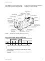
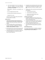
036-21216-003-A-0204
®
TECHNICAL GUIDE
FLEXIBLE LIGHT COMMERCIAL UNIT
SUNLINE ULTRA™
GENERAL
SINGLE PACKAGE AIR-COOLED
3, 4 AND 5 NOMINAL TON
YORK’s Sunline Ultra package units are designed to handle applications ranging from residential to light commercial and any in between. The Sunline Ultra is a unit that
gives you the flexibility and choices you need in today’s
market.
D1HE/D1HG036, 048 and D2HE/D2HG060
12.2 THROUGH 13.2 SEER
FEATURING
AIR CONDITIONERS
•
•
•
•
•
•
•
•
•
•
•
•
•
DHG MODEL SHOWN
•
•
•
•
•
•
COOLING ONLY UNITS
COOLING/GAS HEATING UNITS (NATURAL GAS
OR PROPANE)
LOW PROFILE
QUIET OPERATION
COMMON FOOTPRINT
OPTIONAL FACTORY INSTALLED ECONOMIZERS
OPTIONAL SLIDE IN MOTORIZED DAMPERS
OPTIONAL SLIDE IN ECONOMIZERS
OPTIONAL ELECTRIC HEATERS
OPTIONAL PROPANE CONVERSION KIT
OPTIONAL HIGH ALTITUDE GAS OR PROPANE KIT
OPTIONAL NOx KIT
MODULAR ELECTRICAL CONNECTIONS FOR
EASY OF INSTALLATION
FULL PERIMETER BASE RAILS
TROUBLE FREE UTILITY CONNECTIONS
1” OR 2” THROWAWAY FILTERS
5 YEAR LIMITED WARRANTY ON COMPRESSOR
10 YEAR LIMITED WARRANT ON GAS-FIRED HEAT
EXCHANGERS
1 YEAR LIMITED WARRANTY ON ALL REPLACEMENT PARTS
FOR DISTRIBUTION USE ONLY - NOT TO BE USED AT POINT OF RETAIL SALE
036-21216-003-A-0204
TABLE OF CONTENTS
DESCRIPTION . . . . . . . . . . . . . . . . . . . . . . . . . . . . . . 3
FEATURES . . . . . . . . . . . . . . . . . . . . . . . . . . . . . . . . 3
FACTORY-INSTALLED OPTION . . . . . . . . . . . . . . . 4
FIELD-INSTALLED ACCESSORIES. . . . . . . . . . . . . 4
MECHANICAL SPECIFICATIONS . . . . . . . . . . . . . 24
LIST OF FIGURES
Fig.
1
2
3
4
5
6
7
8
9
10
11
12
13
14
15
16
17
2
Pg.
SUNLINE ULTRA CUTAWAY (MODEL DHG
GAS HEATING). . . . . . . . . . . . . . . . . . . . . . . . . . . . . . . . 5
FIELD POWER WIRING . . . . . . . . . . . . . . . . . . . . . . . . 16
CONTROL WIRING COOLING ONLY . . . . . . . . . . . . . 16
CONTROL WIRING SINGLE STAGE . . . . . . . . . . . . . . 17
CONTROL WIRING COOLING/HEATING . . . . . . . . . . 17
CONTROL WIRING MULTI-STAGE . . . . . . . . . . . . . . . 17
DHE UNIT DIMENSIONS . . . . . . . . . . . . . . . . . . . . . . . 18
ACCESS PANELS AND DISCONNECT . . . . . . . . . . . . 18
UNIT DIMENSIONS DHG UNIT . . . . . . . . . . . . . . . . . . 19
REAR DIMENSIONS OF DHE AND DHG
UNITS 3, 4 & 5 TON UNITS . . . . . . . . . . . . . . . . . . . . . 20
UNIT DIMENSIONS WITH ECONOMIZER
RAINHOOD . . . . . . . . . . . . . . . . . . . . . . . . . . . . . . . . . . 20
DETAIL “B” UNIT WITH FIXED OUTDOOR
AIR/MOTORIZED DAMPER RAINHOOD . . . . . . . . . . . 21
UNIT AND CURB APPLICATION . . . . . . . . . . . . . . . . . 21
ROOF CURB DIMENSIONS DHE/DHG
3, 4 & 5 TON . . . . . . . . . . . . . . . . . . . . . . . . . . . . . . . . . 22
CENTER OF GRAVITY AND CORNER WEIGHTS . . . 22
TYPICAL APPLICATIONS . . . . . . . . . . . . . . . . . . . . . . 23
TYPICAL ROOF-TOP INSTALLATION (DHG) . . . . . . . 23
LIST OF TABLES
Tbl.
1
2
3
4
5
6
7
8
9
10
11
12
13
14
15
16
17
18
19
20
21
22
Pg.
CAPACITY RATING - COOLING / ELECTRIC HEAT . . 5
CAPACITY RATINGS - COOLING / GAS HEATING . . . 6
SOUND POWER RATINGS . . . . . . . . . . . . . . . . . . . . . . 6
PHYSICAL DATA - BASIC UNIT . . . . . . . . . . . . . . . . . . 6
COOLING CAPACITIES - MODELS
DHE/DHG 036 - 85°F - 95ºF. . . . . . . . . . . . . . . . . . . . . . 7
COOLING CAPACITIES - MODELS
DHE/DHG 036 - 105°F - 115ºF. . . . . . . . . . . . . . . . . . . . 8
COOLING CAPACITIES - MODELS DHE/DHG048 . . . 9
COOLING CAPACITIES - MODELS DHE/DHG060 . . 10
SUPPLY AIR BLOWER PERFORMANCE DHE/DHG036 . . . . . . . . . . . . . . . . . . . . . . . . . . . . . . . . 11
SUPPLY AIR BLOWER PERFORMANCE
DHE/DHG048 (4 TON GAS HEAT MODELS) . . . . . . . 12
SUPPLY AIR BLOWER PERFORMANCE
DHE/DHG060 (5 TON GAS HEAT MODELS) . . . . . . . 13
ACCESSORY STATIC RESISTANCE . . . . . . . . . . . . . 13
MOTOR AND DRIVE DATA - BELT-DRIVE BLOWER 14
ELECTRICAL DATA - BASIC UNIT . . . . . . . . . . . . . . . 14
ELECTRICAL DATA - COOLING/ELECTRIC
HEAT DHE036 & 048 . . . . . . . . . . . . . . . . . . . . . . . . . . 15
ELECTRIC HEAT CORRECTION FACTORS
(DHE048) . . . . . . . . . . . . . . . . . . . . . . . . . . . . . . . . . . . 15
FUSE BLOCK ACCESSORY . . . . . . . . . . . . . . . . . . . . 15
ELECTRICAL DATA - COOLING/ELECTRIC
HEAT DHE060 . . . . . . . . . . . . . . . . . . . . . . . . . . . . . . . 16
UTILITIES ENTRY DATA . . . . . . . . . . . . . . . . . . . . . . . 18
CLEARANCES . . . . . . . . . . . . . . . . . . . . . . . . . . . . . . . 19
BASIC UNIT WEIGHT . . . . . . . . . . . . . . . . . . . . . . . . . 22
ACCESSORIES WEIGHT . . . . . . . . . . . . . . . . . . . . . . 22
Unitary Products Group
036-21216-003-A-0204
DESCRIPTION
YORK Sunline Ultra units are high efficiency, convertible, single package air conditioners with a common cabinet and a
common roof curb for the 3, 4 and 5 ton sizes. The units were
designed for residential, light commercial and commercial
applications. They can easily be installed on a roof curb, slab,
roof jack or frame.
All units are self-contained and assembled on rigid full perimeter base rails with fork lift slots on three sides and holes for
overhead rigging. Every unit is completely piped, wired,
charged and tested at the factory to provide for a quick and
easy field installation.
The units are available in cooling only, and cooling with gas
heat. Electric heaters are available as field--installed accessories.
Both bottom and side duct connections are available without
having to swap panels. The installer simply removes the duct
covers for the desired configuration. Economizers may be
used on either bottom and side duct applications with no
modifications required.
All models include a 5-year limited warranty on compressors,
a 10-year limited warranty on gas-fired heat exchangers and
a 1-year limited warranty on all replacement parts.
FEATURES
COMMON FOOTPRINT/COMMON CABINET - All model
sizes and configurations share a common cabinet and a common roof curb. The installer has the flexibility of setting one
curb and placing the proper tonnage unit on that curb after
the internal load has been determined. He can even decide
between gas or electric heat after the curb has been set.
HIGH EFFICIENCY - Units have a high cooling efficiency of
as high as 13.2 SEER and gas / electric models have a minimum AFUE of 80.3%. All efficiencies exceed legislated minimum levels and provide low operating costs.
CONVERTIBLE AIRFLOW DESIGN - Both the side and bottom duct openings are covered when they leave the factory. If
a side supply / side return is desired, you simply remove the
two side duct covers from the outside of the unit and discard
them. If a bottom supply / bottom return is desired, you simply
remove the two knockout panels from the base of the unit and
discard them. No panel cutting or swapping is required! Convertible airflow design allows maximum field flexibility and
minimum inventory.
FACTORY--INSTALLED OPTIONS - Economizers can be
installed at the factory. The economizers are shipped
installed and wired. Only the rain hood needs to be field
assembled and installed. Field labor dollars can be saved by
having the components arrive already installed.
FIELD--INSTALLED ACCESSORIES - Accessories were
designed for quick and easy installation. The motorized
Unitary Products Group
damper and economizers simply slide in, and electrical connections are made by modular plugs. Electric heaters mount
easily, and knockouts are provided in the internal partitions to
connect the elements to the control box single point kit.
The motorized air damper includes a slid-in/plug-in damper
assembly with a rainhood and filters. The outdoor air dampers open when the indoor fan motor is energized. The
damper is capable of providing 0% through 100% of outdoor
return air opening.
The manual outdoor damper provides 0% through 35% or 0%
through 100% of return air opening (field adjustable).
Designed for duct mounted side or bottom supply/return
applications. Includes rain hood assembly and filter.
The 14" high roof curb is shipped knocked down. An insulated deck is not required because the bottom of the unit is
insulated.
Low ambient controls are available to provide stable unit
operation at outdoor temperatures down to 0F.
Propane, high altitude and low NOx kits are also available to
cover all gas heating applications.
WIDE RANGE OF INDOOR AIRFLOWS - All models operate
over a wide range of design conditions with the use of belt-drive blowers. The variable pitch pulley on the blower motor
can be adjusted to obtain the desired supply air CFM.
FULL PERIMETER BASE RAILS - The permanently attached
base rails provide a solid foundation for the entire unit and
protect the unit during shipment. The rails provide fork lift
access from 3 sides, and rigging holes are also provided so
that an overhead crane can be used to place the units on a
roof.
SYSTEM PROTECTION - Internal overload protection is
standard on all compressors. Every unit has a liquid line filter-drier, high and low pressure/loss of charge switches and a
suction line freezestat to protect all system components. All
units will provide cooling at ambient temperatures down to
45F.
UTILITY CONNECTIONS MADE EASY - Gas and electric
utility knockouts are provided in the unit base as well as the
side of the unit. A clearly identified location is provided to
mount a field supplied electrical disconnect switch. Utility
connections can be made quickly and with a minimum
amount of field labor.
SIMPLE CONTROL CIRCUIT - A low voltage printed circuit
board contains a compressor lockout indicator light and a low
voltage terminal strip. An additional set of pin connectors is
also provided to simplify the field interface of external controls. Mate-n-lock plug connectors are used where line and
low voltage wires pass through internal bulkheads. This
allows for easier troubleshooting and component replacement. The electrical control box is not located in the compressor compartment so the access cover can be removed for
3
036-21216-003-A-0204
troubleshooting without affecting the normal system operating pressures.
AIR FILTERS - Units are shipped with 1" throwaway filters.
The unit filter racks can accommodate 1" or 2" filters without
any modifications
FACTORY-INSTALLED OPTION
ECONOMIZERS: Units equipped with a factory-installed
economizer option have dampers that are positioned by a
spring return, fully modulating damper actuator and are capable of introducing up to 100% outdoor air. As the outdoor air
intake dampers open, the return air dampers close. The
changeover from mechanical refrigeration to economizer
operation is determined by a single input electronic enthalpy
control or by a dual input electronic enthalpy control. Simultaneous compressor and economizer operation is also possible.
The single enthalpy system contains a sensor that monitors
the outdoor air which automatically operates the damper
actuator allowing the dampers to open or close.
The dual enthalpy system contains a second sensor that
monitors both the temperature and the humidity of the return
air in addition to the outdoor air sensor described for a single
enthalpy system. The logic module compares the inputs from
both sensors and switches to economizer operation whenever the outdoor air is cooler than the return air for maximum
efficiency of the economizer system.
The economizer is completely wired and installed at the factory. Only the outdoor air hood, including its filters, need be
assembled and installed in the field.
FIELD-INSTALLED ACCESSORIES
SINGLE INPUT ELECTRONIC ENTHALPY ECONOMIZER Includes a slide-in / plug-in damper assembly with fully modulating spring return motor actuator capable of introducing up
to 100% outdoor air, one outdoor air electronic enthalpy sensor and a rain hood with filters. The rain hood is painted to
match the basic unit and must be field-assembled before
installation. Economizer dampers are 2% low leakage type.
DUAL INPUT ELECTRONIC ENTHALPY ECONOMIZER Includes the same damper system and rain hood with filters
as described for a single enthalpy economizer except this
accessory contains two enthalpy sensors. It uses a differential enthalpy control that compares the outdoor air versus the
return air. The logic module then optimizes the economizer
operation for additional savings over the single input economizer.
MOTORIZED AIR DAMPER - Includes a slid-in/plug-in
damper assembly with a rainhood and filters. The outdoor air
dampers open when the indoor fan motor is energized. The
damper is capable of providing 0% through 100% of outdoor
return air opening.
4
MANUAL OUTDOOR DAMPER - Provides 0% through 35%
or 0% through 100% of return air opening (field adjustable).
Designed for duct mounted side or bottom supply/return
applications. Includes rain hood assembly and filter.
ELECTRIC HEATERS - Include nickel chromium elements, a
terminal block, fuses (where required by UL), all the necessary connectors and hardware. All heaters utilize single point
power supply hookup. Capacities from 5 KW thru 30 KW
heating are available.
FUSE BLOCK KITS - These kits have a fuse box with a fuse
block and fuses. They're available for all 460-3-60 volt heaters and 208/230-3-60 volt heaters 7 KW and smaller.
OUTDOOR THERMOSTAT - A 24-volt thermostat providing
two stages of control for units equipped with electric heat
accessories.
ROOF CURB - This 14" high full perimeter roof curb is
shipped knocked down for field assembly and contains duct
supports that can easily be
shifted for the desired unit duct arrangement. No insulated
deck is required because the unit underside is insulated.
START ASSIST KIT - Provides increased starting torque for
single phase units in areas with low voltage conditions. It contains a 12.5 OHM PTCR temperature resistor with a support
clip and hardware for mounting.
LOW AMBIENT KIT - A head pressure controller maintains
stable system operation by reducing the speed of the condenser fan motor when the outdoor temperature is between
45 and 0F. Condenser fan motors with ball bearings and
heavier windings are also available for these low ambient
applications.
ANTI-RECYCLE TIMER - A timer to prevent the unit compressor from short cycling. It assures a 5-minute off-time
between compressor cycles.
PROPANE CONVERSION KIT - Converts a gas-fired heater
from natural gas to propane. It contains main burner orifices,
a pilot orifice and a regulator spring.
LOW NOx KIT (natural gas furnaces only) - Contains five
stainless steel expanded metal sheets for mounting into the
heat exchanger tubes to meet the California low nitrous oxide
emission requirements.
HIGH ALTITUDE CONVERSION (NATURAL AND PROPANE) - Provides orifices for proper furnace operation at altitudes up to 6000 feet. For propane applications, the propane
conversion kit will also be required.
GAS PIPING - This kit contains 1/2" pipe nipples, fittings and
gas cock (including panel access gaskets) required for bottom gas supply connection with external shut-off.
OUTDOOR COIL GUARD - Consists of grille-type sections
for installation over the outdoor coil to protect it from damage.
Unitary Products Group
036-21216-003-A-0204
WALL THERMOSTAT - The units are designed to operate
with 24-volt electronic and electro-mechanical thermostats.
All units can operate with single stage heat / single stage cool
thermostats - with or without the economizer.
.
L O N G L A S T IN G
P O W D E R P A IN T F IN IS H
2
S
V O L T A G E R E L A Y B O A R D
E
T E R M IN A L S T R IP
B E L T D R IV E
B L O W E R M O T
E L E C T R IC A L D IS C O N N E C T
M O U N T IN G L O C A T IO N
( F ie ld In s ta lle d )
L O W
A N D
E L
A C
L O
(E
0 G A U G E A L U M IN IZ E D
T E E L T U B U L A R H E A T
X C H A N G E R
E C T
C E S
C A T
le c /E
R IC H E A T
S O R Y
IO N
le c U n its )
O R
P O W E R V E N T E R M O T O R
W IT H P O S T P U R G E C Y C L E
C O P P E R T U B E /
A L U M IN U M F IN
C O N D E N S IN G C O IL
E C O N O M IZ E R H O O D
H IG H E F F IC IE N C Y
C O M P R E S S O R S
O U T D O O R A IR O P E N IN G
F O R S L ID E -IN /P L U G -IN
IN T N E R A L E C O N O M IZ E R
S ID E R E T U R N A IR
D U C T O P E N IN G
F U L L P E R IM E T E R B A S E
R A IL S W IT H F O R K L IF T
S L O T S A N D L IF T IN G H O L E S
B O T T O M R E T U R N A IR
D U C T O P E N IN G
K N O C K O U T F O R S ID E
G A S S U P P L Y E N T R Y
3 /4 " P V C F E M A L E
C O N D E N S A T E D R A IN
K N O C K O U T F O R B O T T O M
G A S S U P P L Y E N T R Y
T E R M IN A L B L O C K
( F o r S in g le P o in t P o w e r
S u p p ly o n E le c /E le c U n its )
K N O C K O U T S F O R
S ID E P O W E R A N D
C O N T R O L E N T R Y
FIGURE 1 -
K N O C K O U T F O R
P O W E R E N T R Y
B O T T O M
SUNLINE ULTRA CUTAWAY (Model DHG gas heating)
TABLE 1: CAPACITY RATING - COOLING / ELECTRIC HEAT
MODEL
ARI RATINGS1
COOLING CAPACITY
80 / 67-95°F
DHE036
DHE048
42.5
46.5
SEER4
12.25
13.20
EER5
11.10
11.40
DHE060
57.0
12.20
10.60
MBH
SOUND
RATING3
(dBels)
NOMINAL ELECTRIC HEAT CAPACITY2
(kW)
240V
480V
86
87
5, 7, 10,
15 & 20
7, 10,
15 & 20
86
5, 7, 10,
15, 20 & 30
7, 10, 15,
20 & 30
1.
Certified in accordance with the Unitary Small Equipment certification program, which is
based on ARI Standard 210/240.
2.
Heaters are available as accessories - all with single point power supply.
3.
Rated in accordance with ARI Standard 270.
4.
SEER = Seasonal Energy Efficiency Ration - the total cooling output in BTU’s during a normal annual usage period for cooling divided by the total electric power input in watt-hours
during the same period.
5.
EER = Energy Efficiency Ration - the cooling capacity in Btu’s per hour (Btuh) divided by
the power input in watts at any given set of rating conditions, expressed in BTUH per watt
(BTUH/watt).
Unitary Products Group
5
036-21216-003-A-0204
TABLE 2: CAPACITY RATINGS - COOLING / GAS HEATING
ARI RATINGS1
COOLING CAPACITY
80 / 67-95°F
MBH
SEER6
EER7
42.5
42.5
12.25
12.25
11.1
11.1
86
86
46.5
13.20
11.40
87
57.0
12.20
10.60
86
MODEL
DHG036N040
DHG036N079
DHG048N060
DHG048N099
DHG060N079
DHG060N099
1.
2.
GAS HEAT CAPACITY
SOUND
RATING2
(dBels)
INPUT
(MBH)
DOE
OUTPUT
(MBH)
AFUE3
(%)
S.S.E.4
(%)
S.E.5
(%)
TEMP. RISE
(°F)
GAS
LINE SIZE
(in. O.D.)
50
100
75
125
100
125
40
79
59
99
79
99
80.0
80.5
80.9
80.3
80.5
80.3
81.6
80.8
81.6
80.6
80.8
80.6
77.3
77.9
77.3
77.9
73.6
77.9
15-45
40-70
25-55
45-75
25-55
35-65
1/2
1/2
1/2
1/2
1/2
1/2
Certified in accordance with the Unitary Small Equipment certification program, which is based on ARI Standard 210/240.
Rated in accordance with ARI Standard 110, utilization range “A”.
3.
AFUE = Annual Fuel Utilization Efficiency - determined in accordance with DOE test procedure.
4.
S.S.E. = Steady State Efficiency. (Percent Output)
5.
S.E. = California Seasonal Efficiency - determined in accordance with test procedures as specified by the State of California
Energy Commission. Furnaces are available with a low NOx accessory.
6.
SEER = Seasonal Energy Efficiency Ratio - the total cooling output in BTU’s during a normal annual usage period for cooling
divided by the total electric power input in watt-hours during the same period.
7.
EER = Energy Efficiency Ratio - the cooling capacity in Btu’s per hour (Btuh) divided by the power input in watts at any given set of
rating conditions, expressed in BTUH per watt (BTUH/watt).
TABLE 3: SOUND POWER RATINGS1
UNIT
SIZE
CFM
036
048
060
1200
1600
2000
ESP
IWG
0.60
0.55
0.45
BLOWER
SPEED
LOW
HIGH
HIGH
kW
0.60
0.80
1.00
63
84
85
86
SOUND POWER (dB 10-12 Watts)
OCTAVE BAND CENTERLINE FREQUENCY (Hz)
125
250
500
1000
2000
4000
8000
84
74
67
69
62
57
52
85
75
68
70
63
58
53
86
76
69
71
64
59
54
SWL
dB(A)
74
75
76
dBA
@ 10 ft.2
41
42
43
1.
These values have been accessed using a model of sound propagation from a point source into the hermispheric free field. The
dBA values provided are to be used for reference only. Calculation of dBA values cover matters of system design and the fan
manufacturer has no way of knowing the details of each system. This constitutes an exception to any specification or guarantee
requiring a dBA value or sound data in any other form than sound power level ratings.
2.
At a distance of 10 feet from the blower.
TABLE 4: PHYSICAL DATA - BASIC UNIT
MODELS
EVAPORATOR
BLOWER
EVAPORATOR
COIL
CONDENSER
FAN
AIR
FILTERS1
SYSTEM
CHARGE
COMPRESSOR
1.
6
CENTRIGUGAL BLOWER (Dia. x Wd. in.)
FAN MOTOR HP (BELT-DRIVE)
036
12 x 10
1.5
DHE/DHG
048
060
12 x 10
1.5
12 x 10
1.5
4
13
4.3
24
1/2
4,500
2
1
6.6
4
13
5.1
24
1/2
4,200
2
1
6.6
4
13
5.1
24
1/2
4,200
2
1
6.6
REFRIGERANT 22 (pounds/ounces)
10/8
10/*4
10/14
QUANTITY PER UNIT (Hermetic Type)
1 / Recpt.
1 / Recpt.
1/Recpt.
ROWS DEEP
FINS PER INCH
FACE AREA (Sq. Ft.)
PROPELLER DIA. (in.)
FAN MOTOR HP
NOM. CFM TOTAL
QUANITY PER UNIT (15” X 20” X 1”)
QUANTITY PER UNIT (14” X 25” X 1”)
TOTAL FACE AREA (square feet)
Filter racks are adapted for 1” or 2” thick filters.
Unitary Products Group
036-21216-003-A-0204
TABLE 5: COOLING CAPACITIES - MODELS DHE/DHG 036 - 85°F - 95ºF
TEMPERATURE OF AIR ON CONDENSER COIL
AIR ON
EVAPORATOR
COIL
1350
1200
1050
900
SENSIBLE CAPACITY3
TOTAL
CAP.1
MBH
WB
°F
CFM
1500
85°F
POWER
INPUT2
ENTERING DRY BULB, °F
86
83
80
77
74
71
68
72
55.2
3.18
35.2
30.7
26.2
21.8
17.3
#N/A
#N/A
67
49.1
3.13
41.7
37.2
32.8
28.3
23.8
19.4
14.9
62
44.7
3.05
44.7
43.6
39.1
34.6
30.1
25.7
21.2
57
42.4
3.05
42.4
42.4
42.4
37.9
33.4
29.0
24.5
72
55.2
3.18
35.2
30.7
26.2
21.8
17.3
#N/A
#N/A
67
49.1
3.13
41.7
37.2
32.8
28.3
23.8
19.4
14.9
62
44.7
3.05
44.7
43.6
39.1
34.6
30.1
25.7
21.2
57
42.4
3.05
42.4
42.4
42.4
37.9
33.4
29.0
24.5
72
51.9
-3.15
30.0
26.5
23.0
19.5
16.0
#N/A
67
46.1
3.10
35.7
32.2
28.7
25.2
21.7
18.2
14.7
62
42.0
3.02
41.2
37.7
34.2
30.7
27.2
23.7
20.2
57
39.8
3.03
39.8
39.8
37.3
33.8
30.3
26.8
23-3
72
49.4
3.12
27.3
24.3
21.2
182
15.2
#N/A
67
43.9
3.07
32.6
29.6
26.5
23.5
20.5
17.4
14.4
62
40.0
2.99
37.7
34.7
31.6
28.6
25.6
22.5
19.5
57
37.9
3.00
37.9
37.0
34.5
31.4
28.4
25.4
22.3
72
46.9
3.09
24.6
22.1
19.5
16.9
14.4
#N/A
67
41.7
3.04
29.5
26.9
24.4
21.8
19.2
16.7
14.1
62
38.0
2.96
34.2
31.6
29.1
26.5
23.9
21.4
18.8
57
36.0
2.97
36.0
34.2
31.7
29.1
26.5
24.0
21.4
TEMPERATURE OF AIR ON CONDENSER COIL
AIR ON
EVAPORATOR
COIL
CFM
1500
1350
1200
1050
900
1.
2.
3.
95°F
SENSIBLE CAPACITY
TOTAL
CAP.
MBH
POWER
INPUT
72
51.5
67
45.8
62
WB
°F
ENTERING DRY BULB, °F
86
83
80
77
74
71
68
3.44
34.1
29.7
25.2
20.7
16.2
#N/A
#N/A
3.35
40.2
35.7
31.3
26.8
22.3
17.8
13.4
41.2
3.30
41.2
41.2
38.8
34.3
29.8
25.3
20.9
57
39.9
3.35
39.9
39.9
39.9
35.4
31.0
26.5
22.0
72
50.0
3.41
31.5
27.5
23.6
19.6
15.6
#N/A
#N/A
67
44.5
3.32
37.2
33.2
29.2
25.3
2 13
17.3
13.3
62
40.0
3.27
40.0
39.2
36.3
32.3
28.3
24.3
20.3
57
38.8
3.32
38.8
38.8
37.5
33.5
29.6
25.6
21.6
72
48.6
3.38
28.9
25.4
21.9
18.4
14.9
#N/A '
#N/A
67
43.2
3.29
34.2
30.7
27.2
23.7
20.2
16.7
13.2
62
38.9
3.23
38.9
37.2
33.7
30.2
26.7
23.2
19.8
57
37.6
3.29
37.6
37.6
35.1
31.6
28.1
24.6
21.1
72
46.4
3.36
26.2
23.2
20.2
17.2
14.1
#N/A
#N/A
67
41.2
3.27
31.1
28.1
25.0
22.0
19.0
16.0
12.9
62
37.1
3.21
36.2
34.1
31.1
28.0
25.0
22.0
18.9
57
35.9
3.27
35.9
34.9
32.3
29.3
26.3
23.2
20.2
72
44.2
3.34
23.6
21.0
18.4
15.9
13.3
#N/A
#N/A
67
39.3
3.25
28.0
25.4
22.9
20.3
17.7
15.2
12.6
62
35.4
3.20
33.5
30.9
28.4
25.8
23.2
20.7
18.1
57
34.2
3.25
34.2
32.1
29.5
27.0
24.4
21.8
19.3
These capacities are gross ratings. For net capacity, determine the KW of the supply air blower motor from the Blower Performance Table, multiply
this value by 3.415 MBH / KW to determine the motor heat, and deduct this heat from the gross capacity of the unit
These ratings include the compressor and the condenser fan motors but not the supply air blower motor. The total condenser fan motor power input
is 0.36kW. Refer to Tables 10 and 11 for the kW of the supply air blower motor.
These capacities are gross ratings. For net capacity, determine the kW of the supply air blower from Tables 10 and 11, multiply this value by 3.415
MBH/kW to determine the motor heat, and deduct this heat from the gross capacity of the unit.
NOMINAL RATING
Unitary Products Group
ALL SENSIBLE CAPACITY
7
036-21216-003-A-0204
TABLE 6: COOLING CAPACITIES - MODELS DHE/DHG 036 - 105°F - 115ºF
TEMPERATURE OF AIR ON CONDENSER COIL
AIR ON
EVAPORATOR
COIL
1350
1200
1050
900
SENSIBLE CAPACITY3
TOTAL
CAP.1
MBH
WB
°F
CFM
1500
105°F
POWER
INPUT2
ENTERING DRY BULB, °F
86
83
80
77
74
71
68
72
47.6
3.65
32.3
27.8
23.3
18.9
14.4
#N/A
#N/A
67
42.5
3.56
39.0
34.5
30.0
25.6
21.1
16.6
12.1
62
38.0
3.49
38.0
38.0
36.6
32.1
27.6
23.1
18.7
57
37.4
3.54
37.4
37.4
37.4
32.9
28.5
24.0
19.5
72
46.5
3.62
29.7
25.8
21.8
17.8
13.8
#N/A
#N/A
67
41.6
3.53
36.0
32.0
28.0
24.0
20.1
16.1
12.1
62
37.1
3.46
37.1
36.6
34.1
30.1
26.1
22.2
18.2
57
36.5
3.52
36.5
36.5
35.2
31.2
27.2
23.3
19.3
72
45.4
3.60
27.2
23.7
20.2
16.7
12.2
#N/A
#N/A
67
40.6
3.51
33.0
29.5
26.0
22.5
19.0
15.5
12.0
62
36.2
3.44
36.2
35.2
31.7
28.2
24.7
21.2
17.7
57
35.7
3.49
35.7
35.7
33.0
29.5
26.0
22.5
19.0
72
43.2
3.57
24.6
21.6
18.5
12.5
#N/A
#N/A
67
38.7
3.48
29.9
26.9
23.8
20.8
17.8
14.7
11.7
62
34.5
3.41
33.9
32.1
29.0
26.0
23.0
19.9
16.9
57
34.0
3.47
34.0
32.9
30.3
27.2
24.2
21.2
18.1
72
41.1
3.54
22.0
19.4
16.8
14.3
11.7
#N/A
#N/A
67
36.7
3.45
26.8
24.2
21.7
19.1
16.5
14.0
11.4
62
32.8
3.39
31.5
28.9
26.4
23.8
21.2
18.7
16.1
57
32.3
3.44
32.3
30.1
27.5
24.9
22.4
19.8
17.2
TEMPERATURE OF AIR ON CONDENSER COIL
AIR ON
EVAPORATOR
COIL
1350
1200
1050
900
1.
2.
3.
POWER
INPUT
ENTERING DRY BULB, °F
86
83
80
77
74
71
68
72
43.6
3.85
30.4
26.0
21.5
17.0
12.5
#N/A
#N/A
67
39.3
3.76
37.8
33.3
28.8
24.3
19.9
15.4
10.9
62
34.8
3.67
34.8
34.8
34.4
29.9
25.4
20.9
16.5
57
34.9
3.73
34.9
34.9
34.9
30.5
26.0
21.5
17.0
72
42.9
3.83
28.0
24.0
20.0
16.0
12.0
#N/A
#N/A
67
38.6
3.74
34.8
30.8
26.8
22.8
18.8
14.9
10.9
62
34.2
3.66
34.2
34.0
32.0
28.0
24.0
20.0
16.0
57
34.3
3.72
34.3
34.3
32.9
28.9
24.9
21.0
17.0
72
42.2
3.82
25.5
22.0
18.5
15.0
11.5
#N/A
#N/A
67
37.9
3.73
31.8
28.3
24.8
21.3
17.8
14.3
10.8
62
33.6
3.64
33.6
33.1
29.6
26.1
22.6
19.1
15.6
57
33.7
3.70
33.7
33.7
30.9
27.4
23.9
20.4
16.9
72
40.1
3.78
22.9
19.9
16.9
13.8
10.8
#N/A
#N/A
67
36.1
3.69
28.7
25.7
22.6
19.6
16.6
13.5
10.5
62
32.0
3.61
31.6
30.0
27.0
23.9
20.9
17.9
14.9
57
32.1
3.67
32.1
30.9
28.2
25.1
22.1
19.1
16.0
72
38.0
3.75
20.4
17.8
15.2
12.7
10.1
#N/A
#N/A
67
34.2
3.66
25.6
23.0
20.4
17.9
15.3
12.7
10.2
62
30.3
3.58
29.5
26.9
24.4
21.8
19.2
16.7
14.1
57
30.4
3.64
30.4
28.0
25.4
22.9
20.3
17.7
15.2
These capacities are gross ratings. For net capacity, determine the KW of the supply air blower motor from the Blower Performance
Table, multiply this value by 3.415 MBH / KW to determine the motor heat, and deduct this heat from the gross capacity of the unit
These ratings include the compressor and the condenser fan motors but not the supply air blower motor. The total condenser fan motor
power input is 0.36kW. Refer to Tables 10 and 11 for the kW of the supply air blower motor.
These capacities are gross ratings. For net capacity, determine the kW of the supply air blower from Tables 10 and 11, multiply this value
by 3.415 MBH/kW to determine the motor heat, and deduct this heat from the gross capacity of the unit.
NOMINAL RATING
8
SENSIBLE CAPACITY
TOTAL
CAP.
MBH
WB
°F
CFM
1500
115°F
ALL SENSIBLE CAPACITY
Unitary Products Group
036-21216-003-A-0204
TABLE 7: COOLING CAPACITIES - MODELS DHE/DHG048
TEMPERATURE OF AIR ON CONDENSER COIL
AIR ON
EVAPORATOR
COIL
CFM
2000
1800
1600
1400
1200
85°F
WB
°F
72
67
62
57
72
67
62
57
72
67
62
57
72
67
62
57
72
67
62
57
2000
1800
1600
1400
1200
POWER
INPUT2
59
53
47
47
58
53
47
46
57
52
46
45
54
49
43
43
51
46
41
40
3.3
3.2
3.2
3.1
3.3
3.2
3.2
3.1
3.3
3.2
3.2
3.1
3.2
3.1
3.1
3.1
3.2
3.1
3.1
3.0
TOTAL
1
86
83
80
77
74
71
68
CAP.
MBH
46
53
47
47
42
50
47
46
39
47
46
45
35
43
43
43
32
39
41
40
40
49
47
47
37
46
47
46
34
42
46
45
31
39
43
43
29
35
41
40
34
43
47
47
32
41
46
46
30
38
45
45
27
35
42
41
25
32
38
38
28
38
42
41
27
35
41
41
25
33
41
40
23
31
38
37
22
28
35
34
23
32
36
35
22
30
36
35
21
29
36
36
19
27
34
33
18
25
31
31
26
30
29
25
31
30
24
32
31
23
30
29
21
28
27
21
25
24
20
26
25
19
27
27
19
26
25
18
24
24
55
49
44
43
54
48
43
42
53
48
42
41
51
45
40
39
48
42
38
37
SENSIBLE CAPACITY3
ENTERING DRY BULB, °F
POWER
INPUT2
3.5
3.4
3.4
3.3
3.5
3.4
3.4
3.3
3.5
3.4
3.4
3.3
3.5
3.4
3.4
3.3
3.5
3.5
3.4
3.4
86
83
80
77
74
71
43
49
44
43
40
47
43
42
37
45
42
41
34
41
40
39
30
37
38
37
37
47
44
43
35
44
43
42
33
41
42
41
30
37
40
39
27
34
38
37
32
41
44
43
30
39
43
42
28
36
43
41
26
33
40
38
23
30
36
35
26
35
38
37
25
33
38
37
23
32
39
37
22
29
36
34
20
27
33
31
20
30
32
31
20
28
33
32
19
27
34
32
17
25
32
30
16
23
29
28
24
26
26
23
28
27
22
30
28
21
28
26
20
26
24
TEMPERATURE OF AIR ON CONDENSER COIL
AIR ON
EVAPORATOR
COIL
CFM
TOTAL
CAP.1
MBH
95°F
SENSIBLE CAPACITY3
ENTERING DRY BULB, °F
105°F
TOTAL
CAP.1
MBH
WB
°F
72
67
62
57
72
67
62
57
72
67
62
57
72
67
62
57
72
67
62
57
50
45
39
39
50
44
39
38
49
44
39
38
47
42
37
36
44
40
35
34
POWER
INPUT2
3.8
3.7
3.6
3.6
3.8
3.7
3.6
3.6
3.8
3.7
3.6
3.6
3.8
3.7
3.6
3.5
3.7
3.7
3.6
3.5
115°F
SENSIBLE CAPACITY3
ENTERING DRY BULB, °F
TOTAL
86
83
80
77
74
71
68
CAP.1
MBH
41
45
39
39
38
44
39
38
35
43
39
38
32
39
37
36
29
36
35
34
35
44
39
39
33
41
39
38
31
39
39
38
28
35
37
36
25
32
35
34
30
39
39
39
28
36
40
38
26
34
41
38
24
31
38
35
22
29
34
32
24
33
34
33
23
31
35
33
21
30
37
33
20
27
33
31
18
25
30
28
18
27
28
27
18
26
30
28
17
25
32
29
16
23
29
27
15
21
27
25
22
22
22
21
25
23
20
27
24
19
25
23
18
23
21
16
17
16
16
20
18
16
23
19
15
21
18
14
20
18
45
40
35
35
45
40
35
34
45
40
35
34
43
38
33
33
41
36
32
31
SENSIBLE CAPACITY3
ENTERING DRY BULB, °F
POWER
INPUT2
4.0
4.0
3.8
3.8
4.0
4.0
3.9
3.8
4.1
4.1
3.9
3.8
4.0
4.0
3.8
3.7
3.9
3.9
3.8
3.7
86
83
80
77
74
71
39
40
35
35
36
40
35
34
33
40
35
34
30
37
33
33
27
34
32
31
33
40
35
35
31
39
35
34
29
37
35
34
26
34
33
33
24
30
32
31
28
37
35
35
26
34
37
34
24
32
39
34
22
29
35
31
20
27
32
29
22
31
30
29
21
29
32
29
20
27
34
30
18
25
31
27
17
23
28
25
16
25
24
23
16
24
27
24
15
23
30
25
14
21
27
23
13
20
25
22
20
18
18
19
22
19
18
25
20
17
23
19
16
21
18
1.
These capacities are gross ratings. For net capacity, determine the KW of the supply air blower motor from the Blower Performance
Table, multiply this value by 3.415 MBH / KW to determine the motor heat, and deduct this heat from the gross capacity of the unit
2.
These ratings include the compressor and the condenser fan motors but not the supply air blower motor. The total condenser fan
motor power input is 0.36kW. Refer to Tables 10 and 11 for the kW of the supply air blower motor.
3.
These capacities are gross ratings. For net capacity, determine the kW of the supply air blower from Tables 10 and 11, multiply
this value by 3.415 MBH/kW to determine the motor heat, and deduct this heat from the gross capacity of the unit.
NOMINAL RATING
Unitary Products Group
ALL SENSIBLE CAPACITY
9
036-21216-003-A-0204
TABLE 8: COOLING CAPACITIES - MODELS DHE/DHG060
AIR ON
EVAPORATOR
COIL
CFM
2500
2250
2000
1750
1500
WB
°F
72
67
62
57
72
67
62
57
72
67
62
57
72
67
62
57
72
67
62
57
AIR ON
EVAPORATOR
COIL
CFM
2500
2250
2000
1750
1500
WB
°F
72
67
62
57
72
67
62
57
72
67
62
57
72
67
62
57
72
67
62
57
TEMPERATURE OF AIR ON CONDENSER COIL
85°F
TOTAL
CAP.1
MBH
POWER
INPUT2
82
70
67
66
78
67
64
63
75
64
61
60
72
62
59
58
69
59
56
55
4.3
4.2
4.0
4.0
4.3
4.2
4.0
4.0
4.3
4.2
4.0
4.0
4.3
4.2
4.0
4.0
4.2
4.1
4.0
4.0
TOTAL
1
86
83
80
77
74
71
68
CAP.
MBH
56
67
67
66
53
63
64
63
49
58
61
60
44
53
59
58
40
48
56
55
50
61
67
66
47
57
64
63
43
53
61
60
40
49
57
57
36
44
53
54
43
54
66
66
41
51
62
63
38
48
58
59
35
44
53
55
32
40
49
50
37
48
59
59
35
45
56
57
33
42
52
54
30
39
48
50
28
36
44
46
30
41
52
52
29
39
50
51
27
37
47
49
25
34
44
45
24
32
40
42
34
46
46
33
44
45
32
42
43
30
39
40
28
36
37
28
39
39
27
38
39
26
36
38
25
34
36
23
32
33
76
65
62
61
73
62
60
58
70
60
57
56
67
58
55
54
65
56
53
52
SENSIBLE CAPACITY3
ENTERING DRY BULB, °F
POWER
INPUT2
4.6
4.5
4.5
4.4
4.6
4.5
4.4
4.4
4.6
4.5
4.4
4.4
4.6
4.5
4.4
4.4
4.6
4.5
4.4
4.4
86
83
80
77
74
71
68
54
65
62
61
50
60
60
58
46
56
57
56
43
51
55
54
39
46
53
52
48
58
62
61
44
54
60
58
41
50
57
56
38
46
54
54
34
42
51
51
41
51
62
61
38
48
59
58
36
45
55
56
33
41
51
51
30
38
47
47
34
45
55
54
32
42
53
52
30
39
50
50
28
37
46
47
26
34
43
43
28
38
49
47
26
36
47
46
25
34
45
45
24
32
42
42
22
30
39
39
31
42
41
30
41
40
29
39
39
27
37
37
26
35
35
25
35
34
24
35
34
23
34
34
22
32
32
21
30
30
TEMPERATURE OF AIR ON CONDENSER COIL
105°F
TOTAL
CAP.1
MBH
68
60
56
55
67
58
55
54
65
57
53
52
62
54
51
50
59
52
48
47
POWER
INPUT2
5.0
4.8
4.8
4.7
4.9
4.8
4.7
4.7
4.9
4.8
4.7
4.7
4.9
4.8
4.7
4.6
4.9
4.7
4.7
4.6
115°F
SENSIBLE CAPACITY3
ENTERING DRY BULB, °F
TOTAL
86
83
80
77
74
71
68
CAP.1
MBH
51
60
56
55
48
57
55
54
44
54
53
52
40
49
51
50
36
44
48
47
44
55
56
55
42
52
55
54
39
48
53
52
35
44
50
50
32
40
47
47
38
49
56
55
36
46
54
53
33
43
52
52
31
40
48
48
28
36
43
43
31
42
49
48
30
40
48
47
28
38
46
46
26
35
43
43
24
32
39
39
25
35
43
42
24
34
42
41
23
32
41
41
21
30
38
38
20
28
35
35
29
36
35
28
36
35
27
36
36
25
33
33
24
31
31
22
29
28
22
30
29
22
30
30
21
29
29
20
27
27
61
55
50
49
60
54
49
49
60
54
49
48
56
51
46
46
53
48
43
43
SENSIBLE CAPACITY3
ENTERING DRY BULB, °F
POWER
INPUT2
5.3
5.1
5.1
5.0
5.3
5.1
5.0
5.0
5.2
5.1
5.0
5.0
5.2
5.0
5.0
4.9
5.2
5.0
4.9
4.9
86
83
80
77
74
71
68
48
55
50
49
45
53
49
49
42
52
49
48
38
47
46
46
34
43
43
43
41
53
50
49
39
50
49
49
36
47
49
48
33
42
46
46
30
38
43
43
35
46
50
49
33
44
49
49
31
41
48
48
28
38
44
44
26
34
40
40
28
39
43
43
27
38
43
43
26
36
43
42
24
33
39
39
22
30
36
36
21
33
37
36
21
32
37
37
20
30
37
37
19
28
34
34
18
26
32
31
26
30
29
26
31
31
25
32
32
23
30
29
22
27
27
20
23
23
20
25
25
20
26
26
19
25
25
18
23
23
1.
These capacities are gross ratings. For net capacity, determine the KW of the supply air blower motor from the Blower Performance
Table, multiply this value by 3.415 MBH / KW to determine the motor heat, and deduct this heat from the gross capacity of the unit
2.
These ratings include the compressor and the condenser fan motors but not the supply air blower motor. The total condenser fan
motor power input is 0.36kW. Refer to Tables 10 and 11 for the kW of the supply air blower motor.
3.
These capacities are gross ratings. For net capacity, determine the kW of the supply air blower from Tables 10 and 11, multiply
this value by 3.415 MBH/kW to determine the motor heat, and deduct this heat from the gross capacity of the unit.
NOMINAL RATING
10
95°F
SENSIBLE CAPACITY3
ENTERING DRY BULB, °F
ALL SENSIBLE CAPACITY
Unitary Products Group
036-21216-003-A-0204
TABLE 9: SUPPLY AIR BLOWER PERFORMANCE -DHE/DHG036
MODEL
DHE/DHG
AVAILABLE EXTERNAL STATIC PRESSURE - IWG2
AIR
FLOW
CFM
0.20
RPM
036
MODEL
DHE/DHG
0.30
WATTS RPM
0.40
0.50
0.60
0.70
0.80
WATTS
RPM
WATTS
RPM
WATTS
RPM
WATTS
RPM
WATTS
RPM
WATTS
2000
843
860
880
925
919
1005
956
1065
993
1145
1030
1195
1067
1235
1900
817
775
854
850
893
920
930
995
970
1065
1008
1125
1046
1170
1800
790
700
828
760
867
840
906
905
944
980
985
1040
1025
1100
1700
-
-
802
670
840
745
881
815
920
900
961
970
1001
1030
1600
-
-
-
-
818
665
858
740
898
820
940
890
980
950
1500
-
-
-
-
-
-
842
695
882
755
922
835
962
895
1400
-
-
-
-
-
-
833
650
867
705
904
765
942
820
1300
-
-
-
-
-
-
-
-
858
665
893
725
932
785
1200
-
-
-
-
-
-
-
-
847
640
880
680
916
730
AVAILABLE EXTERNAL STATIC PRESSURE - IWG2
AIR
FLOW
CFM
0.90
RPM
036
1
1.00
WATTS RPM
1.10
1.20
1.30
1.40
1.50
WATTS
RPM
WATTS
RPM
WATTS
RPM
WATTS
RPM
WATTS
RPM
WATTS
2000
1103
1270
-
-
-
-
-
-
-
-
-
-
-
-
1900
1085
1210
-
-
-
-
-
-
-
-
-
-
-
-
1800
1064
1145
1102
1180
-
-
-
-
-
-
-
-
-
-
1700
1040
1075
1081
1115
1121
1140
-
-
-
-
-
-
-
-
1600
1020
1005
1060
1050
1100
1085
-
-
-
-
-
-
-
-
1500
1003
945
1044
995
1086
1035
-
-
-
-
-
-
-
-
1400
982
880
1024
920
1067
965
1107
1000
-
-
-
-
-
-
1300
970
835
1010
870
1053
920
1099
960
-
-
-
-
-
-
1200
953
780
992
815
1034
855
1080
905
-
-
-
-
-
-
1.
For 208 Volts multiply values by 0.95.
2.
Includes allowances for a wet evaporator coil, 1” filters, and the heat exchangers. Refer to Table 12 for resistance values on applications other than gas / electric units with side duct airflows.
Unitary Products Group
11
036-21216-003-A-0204
TABLE 10: SUPPLY AIR BLOWER PERFORMANCE DHE/DHG0481 (4 TON GAS HEAT MODELS)
UNIT
SIZE
(MBH
AIR
FLOW
CFM
048
2000
1900
1800
1700
1600
1500
1400
1300
1200
UNIT
SIZE
(MBH
AIR
FLOW
CFM
048
2000
1900
1800
1700
1600
1500
1400
1300
1200
12
RPM
843
817
790
-
0.20
Watts
860
775
700
-
RPM
1103
1085
1064
1040
1020
1003
982
970
953
0.90
Watts
1270
1210
1145
1075
1005
945
880
835
780
RPM
880
854
828
802
-
0.30
Watts
925
850
760
670
-
AVAILABLE EXTERNAL STATIC PRESSURE - IWG2
0.40
0.50
0.60
RPM
Watts
RPM
Watts
RPM
Watts
919
1005
956
1065
993
1145
893
920
930
995
970
1065
867
840
906
905
944
980
840
745
881
815
920
900
818
665
858
740
898
820
842
695
882
755
833
650
867
705
858
665
847
640
RPM
1030
1008
985
961
940
922
904
893
880
0.70
Watts
1195
1125
1040
970
890
835
765
725
680
RPM
1067
1046
1025
1001
980
962
942
932
916
0.80
Watts
1235
1170
1100
1030
950
895
820
785
730
RPM
1102
1081
1060
1044
1024
1010
992
1.00
Watts
1180
1115
1050
995
920
870
815
AVAILABLE EXTERNAL STATIC PRESSURE - IWG2
1.10
1.20
1.30
RPM
Watts
RPM
Watts
RPM
Watts
1121
1140
1100
1085
1086
1035
1067
965
1107
1000
1053
920
1099
960
1034
855
1080
905
-
RPM
-
1.40
Watts
-
RPM
-
1.50
Watts
-
1.
Models shown at 230/460 Volts with side duct connections.
2.
Includes allowances for a wet evaporator coil, 1” filters, and the heat exchangers. Refer to the static resistances table for resistance values on applications other than gas/electric units with side duct airflows.
Unitary Products Group
036-21216-003-A-0204
TABLE 11: SUPPLY AIR BLOWER PERFORMANCE DHE/DHG0601 (5 TON GAS HEAT MODELS)
UNIT
SIZE
(MBH)
AIR FLOW
CFM
060
2500
2400
2300
2200
2100
2000
1900
1800
1700
1600
1500
UNIT
SIZE
(MBH)
AIR FLOW
CFM
060
2500
2400
2300
2200
2100
2000
1900
1800
1700
1600
1500
0.20
RPM
Watts
1059
1560
1032
1405
1005
1260
980
1160
930
1060
877
950
-
0.30
RPM
Watts
1077
1590
1054
1470
1024
1275
1002
1170
957
1070
908
975
-
AVAILABLE EXTERNAL STATIC PRESSURE - IWG2
0.40
0.50
0.60
RPM
Watts
RPM
Watts
RPM
Watts
1095
1630
1114
1650
1134
1660
1074
1525
1094
1560
1116
1595
1049
1370
1069
1440
1090
1475
1022
1190
1044
1250
1066
1350
983
1080
1010
1100
1039
1160
941
1000
976
1020
1009
1050
894
885
940
940
980
980
855
815
903
860
950
905
884
815
925
850
864
770
908
805
882
740
RPM
1158
1140
1116
1090
1064
1040
1014
988
964
948
926
0.70
Watts
1685
1620
1505
1410
1260
1100
1020
940
880
835
780
RPM
1181
1167
1142
1117
1092
1070
1047
1022
1001
987
965
0.80
Watts
1720
1640
1535
1440
1340
1225
1095
970
910
870
830
0.90
RPM
Watts
1193
1665
1170
1580
1148
1480
1121
1385
1100
1285
1079
1180
1058
1060
1035
960
1020
900
1004
860
1.00
RPM
Watts
1202
1620
1180
1530
1155
1425
1133
1340
1110
1240
1090
1135
1071
1030
1056
965
1038
880
AVAILABLE EXTERNAL STATIC PRESSURE IWG1
1.10
1.20
1.30
RPM
Watts
RPM
Watts
RPM
Watts
1190
1475
1169
1385
1205
1445
1143
1280
1178
1330
1222
1375
1122
1190
1158
1240
1196
1295
1103
1100
1134
1140
1164
1175
1088
1035
1118
1065
1145
1105
1070
925
1101
980
1130
1045
RPM
1197
1170
1158
1.40
Watts
1205
1130
1075
RPM
1198
1184
1.50
Watts
1150
1110
1.
Models shown at 230/460 Volts with side duct connections.
2.
Includes allowances for a wet evaporator coil, 1” filters and the heat exchangers. Refer to Table 12 for resistance values on applications other than gas / electric units with side duct airflows.
TABLE 12: ACCESSORY STATIC RESISTANCE
1000
1200
1400
EXTERNAL STATIC PRESSURE DROP
RESISTANCE, IWG
CFM
1600
1800
2000
2200
2400
2600
2800
3000
0.07
0.08
0.09
0.11
0.13
0.15
0.17
0.20
0.23
0.26
0.30
0.04
0.06
0.05
0.07
0.06
0.08
0.07
0.09
0.08
0.11
0.10
0.13
0.12
0.15
0.14
0.17
0.16
0.20
0.19
0.23
0.22
0.26
BOTTOM DUCT CONNECTIONS1
0.06
0.07
0.08
0.09
0.10
0.11
0.12
0.14
0.16
0.19
0.22
COOLING ONLY2
0.08
0.10
0.12
0.14
0.16
0.18
0.20
0.23
0.26
0.29
0.32
DESCRIPTION
ECONMIZER1 2
ELECTRIC
5-15 kW
HEATERS3
20 - 30 kW
1.
Deduct these resistance values from the available external static pressure shown in Tables 10 and 11.
2.
The pressure through the economizer is greater for 100% outdoor air than for 100% return air. If the resistance of the return air
duct system is less than 0.25 IWG, the unit will deliver less CFM during full economizer operation.
3.
Add these resistance values to the available static resistance values on Tables 10 and 11.
Unitary Products Group
13
036-21216-003-A-0204
TABLE 13: MOTOR AND DRIVE DATA - BELT-DRIVE BLOWER
ADJUSTABLE
MOTOR PULLEY
PITCH
BORE
DIA.
(in.)
(in.)
MOTOR1
BLOWER
RANGE
(RPM)
HP
RPM
FRAME
SIZE
SERVICE
FACTOR
780 - 1120
11/2
1,725
56
1.15
2.4 - 3.4
7/
DHE/DHG048
790 - 1,120
1/
2
1
1,725
56
1.15
2.4 - 3.4
7/
DHE/DHG060
850 - 1,220
11/2
1,725
56
1.15
2.4 - 3.4
7/
MODEL
DHE/DHG 036
1.
FIXED
BLOWER PULLEY
PITCH
BORE
DIA.
(in.)
(in.)
BELT
PITCH
LENGHT
(in.)
DESIGNATION
8
5.7
1
37.3
A36
8
5.7
1
37.3
A36
8
5.2
1
37.3
A36
All motors have solid bases and are inherently protected. These motors can be selected to operate into their service factor
because they are located in the moving air, upstream of any heating device
TABLE 14: ELECTRICAL DATA - BASIC UNIT
MODEL
DHE/
DHG
036
048
060
14
POWER
SUPPLY
208/230-3-60
460-3-60
208/230-3-60
460-3-60
208/230-3-60
460-3-60
VOLTAGE
LIMITATIONS1
MIN.
MAX.
RLA
LRA
COND.
FAN
MOTOR
FLA
187
414
187
414
187
414
253
504
253
504
253
504
14.1
7.1
10.0
5.2
16.0
8.3
110
54
110.0
54.0
137.0
69.0
2.3
1.4
2.3
1.4
2.3
1.4
COMPRESSOR
1.
Rated in accordance with ARI Standard 110, utilization range “A”..
2.
Dual element, time delay type.
SUPPLY
AIR
AMPACITY
AMPS
TOTAL
UNIT
AMPACITY
AMPS
MAX.
FUSE
SIZE2
AMPS
5.3
3.1
5.2
2.6
6.0
3.0
25.2
13.3
23.9
12.4
28.3
14.8
35
20
35
15
40
20
MAX.
HACR
BREAKER
SIZE
AMPS
35
20
35
15
40
20
Unitary Products Group
036-21216-003-A-0204
TABLE 15: ELECTRICAL DATA - COOLING/ELECTRIC HEAT DHE036 & 048
MODEL
DHE
208-3-60
036
230-3-60
460-3-60
MAX.
FUSE
SIZE1
AMPS
MAX.
SIZE
HACR2
AMPS
4.0
1
11.0
25.2
35
35
2CE045007254
2CE04501025
2CE04501525
2CE04502025
5.6
1
15.6
26.2
35
35
8.0
11.9
15.9
1
2
2
22.1
33.1
44.2
34.2
48.1
61.9
35
50
70
35
50
70
2CE045005254
5.3
1
12.7
25.2
35
35
2CE045007254
2CE04501025
2CE04501525
2CE04502025
7.5
1
18.0
29.2
35
35
10.6
15.9
21.2
1
2
2
25.5
38.2
51.0
38.5
54.4
70.4
40
60
80
40
60
80
2CE045007464
6.8
1
8.2
14.1
20
15
2CE045010464
10.1
1
12.1
19.1
20
20
13.6
1
16.4
24.3
25
25
19.5
2
23.5
33.2
35
35
2CE045005254
4.0
1
11.0
26.0
35
35
4
5.6
1
15.6
26.9
35
35
8.0
11.9
15.9
1
2
2
22.1
33.1
44.2
35.3
48.8
62.7
35
50
70
35
50
70
2CE045005254
5.3
1
12.7
26.0
35
35
4
7.5
1
18.0
30.1
35
35
10.6
15.9
21.2
1
2
2
25.5
38.2
51.0
39.4
55.3
71.2
40
60
80
40
60
80
2CE045007464
6.8
1
8.2
14.0
15
15
2CE045010464
10.1
1
12.1
18.9
20
20
13.6
1
16.4
24.2
25
25
19.5
2
23.5
33.1
35
35
5.3
5.3
3.1
4
6.0
2CE04500725
2CE04501025
2CE04501525
2CE04502025
460-3-60
TOTAL
UNIT
AMPACITY
AMPS
2CE045005253
2CE04500725
2CE04501025
2CE04501525
2CE04502025
230-3-60
TOTAL
AMPS
STAGES
2CE045015464
208-3-60
ELECTRIC HEATERS
kW
2CE04502046
048
SUPPLY
AIR
BLOWER
MOTOR
FLA
HEATER
ACCESSORY
MODEL
NUMBER
POWER
SUPPLY
2CE04501546
4
2CE04502046
4
6.0
3.0
1.
Dual element, time delay type.
2.
Standard circuit breakers may be used in Canada and on applications over 60 amps where the heaters are separately fused.
3.
These electric heaters DO NOT include a fuse box. If a fuse box is required to meet a local code (e.g. Chicago), refer to Table 17
for fuse block accessories available for field installation.
4.
These electric heaters DO NOT include a fuse box. If a fuse box is required to meet a local code (e.g. Chicago), refer to Table 17
for fuse block accessories available for field installation.
TABLE 16: ELECTRIC HEAT CORRECTION
FACTORS (DHE048)
NOMINAL VOLTAGE
VOLTAGE
208
240
480
600
208
230
460
575
kW CAP
MULTIPLIER
1.00
0.92
0.92
0.92
TABLE 17: FUSE BLOCK ACCESSORY
2FB04700425
2FB04700546
Unitary Products Group
208/240 Volts
460 Volts
15
036-21216-003-A-0204
TABLE 18: ELECTRICAL DATA - COOLING/ELECTRIC HEAT DHE060
MODEL
DHE
POWER
SUPPLY
208-3-60
060
230-3-60
460-3-60
HEATER
ACCESSORY
MODEL
NUMBER
SUPPLY
AIR
BLOWER
MOTOR
FLA
ELECTRIC HEATERS
TOTAL
AMPS
TOTAL
UNIT
AMPACITY
AMPS
MAX.
FUSE
SIZE1
AMPS
MAX.
SIZE
HACR2
AMPS
kW
STAGES
2CE045005253
4.0
1
11.0
26.0
40
40
2CE045007254
2CE04501025
2CE04501525
2CE04502025
2CE04503025
5.6
1
15.6
26.9
40
40
8.0
11.9
15.9
22.2
1
2
2
2
22.1
33.1
44.2
61.7
35.1
48.9
62.7
84.6
40
50
70
90
40
50
70
90
2CE045005254
5.3
1
12.7
26.0
40
40
4
7.5
1
18.0
30.1
40
40
10.6
15.9
21.2
29.6
1
2
2
2
25.5
38.2
51.0
71.2
39.4
55.3
71.2
96.5
40
60
80
100
40
60
80
100
2CE045007464
6.8
1
8.2
14.0
20
20
2CE045010464
10.1
1
12.1
18.9
20
20
13.6
1
16.4
24.2
25
25
4
2CE04502046
19.5
2
23.5
33.1
35
35
2CE045030464
28.8
2
34.6
47.1
50
50
2CE04500725
2CE04501025
2CE04501525
2CE04502025
2CE04503025
2CE045015464
6.0
6.0
3.0
1.
Dual element, time delay type.
2.
Standard circuit breakers may be used in Canada and on applications over 60 amps where the heaters are separately fused.
3.
These electric heaters DO NOT include a fuse box. If a fuse box is required to meet a local code (e.g. Chicago), refer to Table 17
for fuse block accessories available for field installation.
C O O L IN G
O N L Y (2 4 V O L T T H E R M O S T A T )
T H E R M O S T A T
T E R M IN A L S
U N IT T E R M IN A L
S T R IP T B 1
1
R V
R
Y C
Y 1
2 4 V O L T
T R A N S F O R M E R
Y 2
FIGURE 2 -
FIELD POWER WIRING
G F
B
1 2 4 V O
R E M O V
T O P R E
T H E E C
S E C O N
L T
E
V
O
D
T H
J U
E N
N O
S T
E R M
M P E
T S IM
M IZ E
A G E
FIGURE 3 -
16
R
O S
J
U L
R .
O F
T A
1 F
T A
IF
C O
T 2 T H
R O M
N E O U
Y O U
O L IN
0 7
T E
S
W A
G ,
7 0 1 0 2 4 IF
R M IN A L S
O P E R A T IO
N T T O C O
U S E T H E
T H
8 A
N
N T
T H
E U
N D
O F
R O
E R
N IT
1 0 O
T H E
L T H
M O S
H A S
N T
C O
E E
T A T
A N
H E R
M P R
C O N
2 T H
E C O N O M IZ E R ,
E L A Y B O A R D
E S S O R A N D
O M IZ E R O N A
0 4 7 0 1 2 2 4 .
CONTROL WIRING COOLING ONLY
Unitary Products Group
036-21216-003-A-0204
C O O L IN G
/ H E A T IN G (E L E C T R O N IC T H E R M O S T A T )
S IN G L E S T A G E
T H E R M O S T A T
T E R M IN A L S
A D D
J U M P E R
A D D
J U M P E R
1
R H
U N IT T E R M IN A L
S T R IP T B 1
R C
R
T H E R M O S T A T
T E R M IN A L S
4
O N IC P
U N IT H A
H E R E L
E S S O R
M IZ E R O
R O
S
A Y
A N
N
FIGURE 4 -
R A M M A
D E C O
O A R D T
T H E E C
S E C O N
B L E
N O M
O P R
O N O
D S T
T H E
IZ E R
E V E
M IZ
A G E
R M O
, R E
N T
E R .
O F
A T
V E
U L
Y O
O L
T H E R M O S T A T
T E R M IN A L S
W 2
G
B
2 E
J U
T A
U W
IN G
T 0 7
M P
N E O
A N
, U
7 0 1
E R
U S
T T
S E
0 2 4 (
J 1 F R
O P E
O C O
T H E R
IN C L U
O M T
R A T IO
N T R O
M O S T
D E
E R
N
L T
A T
S S
M IN
O F
H E
2 E
R H
U N IT T E R M IN A L
S T R IP T B 1
R C
R
Y
Y 1
X
N O T
U S E D
L E D 2
C O M
U B B A S E ).
A L S 8 A N D
T H E
N
4
A 1
A D D
J U M P E R
A 2
T O R E M O T E S E N S O R
2 T H 0 4 0 7 0 2 2 2 4 IF U S E D
T
T
T 0 4 7 0 0 2 2 4 .
1
W
3
L E D 1
(2 4 V O L T T H E R M O S T A T )
Y 2
Y 2
W 1
B
CONTROL WIRING SINGLE STAGE
C O O L IN G /H E A T IN G
A D D
J U M P E R
S T
M O
S IM
IF
C O
2 4 V O L T
T R A N S F O R M E R
Y 1
2
W 2
G
G
A N
B
D
A
R
G
2 4 V O L T
T R A N S F O R M E R
E L E C T R
IF T H IS
1 0 O N T
C O M P R
E C O N O
R H
W 1
B
1
U N IT T E R M IN A L
S T R IP T B 1
Y 2
W 1
G
R C
Y 1
Y 1
Y
W
1
1
E L E C T R O N IC P R O G R A M M A B L E T H E R M O S T A T 2 E T 0 4 7 0 0 2 2 4 (IN C L U D E S S U B B A S E )
2
S E C O N D
3
S E C O N D S T A G E H E A T IN G
E L E C T R IC H E A T E R .
4
R E
P 6
O U
T H
M O
O N
T -P
E R M
V E
U
U T
O
S T A G E C O O L IN G
J U M
N IT S
T O
S T A
FIGURE 6 -
B E R
W IT
C L O
T S W
J
H
S E
IT
2 F
E C
T H
C H
R O
O N
E
E S
IS N O T R E Q U IR E D
O N
U N IT S L E S S E C O N O M IZ E R .
IS O N L Y R E Q U IR E D O N U N IT S W IT H
M T
M IZ
O U T
T O
E R
E R
D O
T H
M IN A L S 4
. T E R M IN
O R E C O N
E S E T -B A
A N D 9 O N J
A L S A 1 A N D
O M IZ E R D A
C K P O S IT IO
A T W O
S T A G E
U M P E R P L U G C O N N E C T O R
A 2 P R O V ID E A R E L A Y
M P E R S W H E N T H E
N .
CONTROL WIRING MULTI-STAGE
2 4 V O L T
T R A N S F O R M E R
W 1
W 2
G
G
B
2 4
R E
T O
T H
S E
V O
M O
P R
E E
C O
W IT H
1
L T
V E
E V
C O
N D
T W
O
T H
J U
E N
N O
S T
FIGURE 5 -
E R M
M P E
T S IM
M IZ E
A G E
S T A G
R
O S T A T
J 1 F R
U L T A N
R . IF Y
O F C O
E S O F
2 T H
O M
E O U
O U
O L IN
H E A
0 7 7 0 1 0 2 4 .
T E R M IN A L S
S O P E R A T
W A N T T O C
G O R H A V E
T , U S E T H E
IF T H E
8 A N
IO N O
O N T R
A N D
R M O S
U
D 1
F T
O L
E L
T A
N IT
0 O
H E
T H
E C
T 2
H A S
N T H
C O M
E R E
T R IC
T H 0 4
A N E C
E R E L
P R E S
C O N O
H E A T
7 1 0 2 4
O N O M IZ
A Y B O A R
S O R A N D
M IZ E R O
A C C E S S
E R ,
D
N A
O R Y
CONTROL WIRING COOLING/HEATING
Unitary Products Group
17
036-21216-003-A-0204
R E T U R N A IR
S U P P L Y A IR
O U T D O O R A IR
O U T D O O R A IR
(E c o n o m iz e r )
All dimensions are in inches. They are
subject to change without notice. Certified dimensions will be provided upon
request.
FIGURE 7 -
DHE UNIT DIMENSIONS
TABLE 19: UTILITIES ENTRY DATA
HOLE
KNOCKOUT
SIZE (DIA.)
A
7/8”1
B
2”
C
D
1-5/8”
1-1/2”
USED FOR
Control Wiring (Side or
Bottom)2
Power Wiring (Side or
Bottom)
Gas Piping (Front)
Gas Piping (Bottom)
1.
Knockouts in the bottom of the unit can be located by
the slice in the insulation
2.
DO NOT remove the 2” knockout ring.
FIGURE 8 -
ACCESS PANELS AND DISCONNECT
NOTE: Units and ductwork of DHE models are approved for
zero clearance to combustible materials when
equipped with electric heaters
18
Unitary Products Group
036-21216-003-A-0204
R E T U R N A IR
S U P P L Y A IR
O U T D O O R A IR
O U T D O O R A IR
(E c o n o m iz e r )
All dimensions are in inches. They are
subject to change without notice. Certified dimensions will be provided upon
request.
FIGURE 9 -
UNIT DIMENSIONS DHG UNIT
TABLE 20: CLEARANCES
FRONT
BACK
LEFT SIDE (Filter Access)
RIGHT SIDE (Cond. Coil)
DHE UNITS
DHG UNITS
24”
32”
12” (Less Economizer)
36” (With Economizer or
Fixed Air/Motorized
Damper)
24” (Less Economizer)
36” (With Economizer)
24”
BELOW UNIT1
0”
ABOVE UNIT2
72” (For Condenser Air
Discharge)
1.
Units may be installed on combustible floors made from
wood or class A, B, or C roof covering material.
2.
Units must be installed outdoors. Overhanging structures or shrubs should not obstruct condenser air discharge outlet.
Unitary Products Group
NOTE: DHG modes must be provided a 1” clearance
between any combustible material and the supply
air ductwork for a distance of 2 feet from the unit.
The products of combustion must not be allowed to accumulate with a confined space and recirculate. Locate unit so that
the vent air outlet hood is at least.
•
•
•
Three feet above any forced air inlet located within 10
horizontal feet (excluding those integral to the unit).
Four feet below, 4 horizontal feet from, or 1 foot above
any door or gravity air inlet into the building.
Four feet from electric meters, gas meters, regulators
and relief equipment.
19
036-21216-003-A-0204
11-1/2
3
17-1/2
11-1/2
6-1/2
17-1/2
4-5/8
7-7/8
FIGURE 10 - REAR DIMENSIONS OF DHE AND DHG UNITS 3, 4 & 5 TON UNITS
Duct covers - units are shipped with all air duct openings covered.
For bottom duct applications:
•
For side duct applications:
•
Remove and discard the supply and return air duct
covers.
•
Connect ductwork to duct flanges on the rear of the unit.
•
•
•
•
2 7 -1 /2
remove the side supply air duct cover to gain access to
the bottom supply air knockout panel.
Remove and discard the bottom knockout panel.
Replace the side duct cover.
With filter section access panel removed from the unit,
remove and discard the bottom return air knockout
panel.
Replace the filter Access panel.
1 -5 /8
2 7 -1 /2
1 9 -3 /4
1 9 -1 /2
4 4 -7 /8
FIGURE 11 - UNIT DIMENSIONS WITH ECONOMIZER RAINHOOD
20
Unitary Products Group
036-21216-003-A-0204
2 7 -1 /2
7 -1 /4
2 7 -1 /2
1 0 -1 /4
3 -1 /2
1 9 -1 /8
8 -1 /4
"A "
4 4 -7 /8
L .H . E N D V IE W
R E A R V IE W
4 -3 /8
D IM E N S IO N "A "
F IX E D
O U T D O O R
A IR D A M P E R
1 2
M O T O R IZ E D
D A M P E R
1 6 -1 /2
FIGURE 12 - DETAIL “B” UNIT WITH FIXED OUTDOOR AIR/MOTORIZED DAMPER RAINHOOD
3.69"
3.56"
BASE RAIL
FIGURE 13 - UNIT AND CURB APPLICATION
Unitary Products Group
21
036-21216-003-A-0204
FIGURE 14 - ROOF CURB DIMENSIONS DHE/DHG 3, 4 & 5 TON
C O R N E R "D "
C O R N E R "C "
8 2 -1 /4
C O R N E R "A "
4 4 -7 /8
C O N D E N S E R C O IL
E N D O F U N IT
4 0 -3 /4
1 9 -3 /4
C O R N E R "B "
FIGURE 15 - CENTER OF GRAVITY AND CORNER WEIGHTS
TABLE 22: ACCESSORIES WEIGHT
TABLE 21: BASIC UNIT WEIGHT
UNIT
DHG036
DHG048
DHG060
DHE036
DHE048
DHE060
1.
22
UNIT
WEIGHT
(lbs.)
665
680
715
565
610
645
CORNER WEIGHTS1
“A”
“B”
“C”
“D”
188
192
202
160
172
182
185
189
199
157
169
179
145
148
155
123
133
140
147
152
159
125
136
144
DESCRIPTION
ECONOMIZER
MOTORIZED OUTDOOR AIR DAMPER
5-7 kW
ELECTRIC HEAT
10-15 kW
(nom. kW DHE only)
20-30 kW
ROOF MOUNTNG CURB
RELIEF/FIXED AIR DAMPER
WEIGHT (lbs.)
50
26
18
23
28
92
10
Weight = Unit with economizer and high heat.
Unitary Products Group
036-21216-003-A-0204
ROOF JACK
INSTALLATION
ROOF CURB
INSTALLATION
SLAB ON GROUND
INSTALLATION
FIGURE 16 - TYPICAL APPLICATIONS
FIGURE 17 - TYPICAL ROOF-TOP INSTALLATION (DHG)
Unitary Products Group
23
036-21216-003-A-0204
MECHANICAL SPECIFICATIONS
GENERAL DESCRIPTION
Single packaged outdoor mounted rooftop with built in field
convertible duct connections for vertical discharge/return air
or horizontal discharge/return air configuration. Cooling performance shall be rated in accordance with DOE and ARI test
procedures. Units shall be CSA Certified to ANSIZ21.47 standards and UL 1995/CAN/CSA No. 236-M90 conditions.
EQUIPMENT
Factory-assembled, single-piece heating and cooling unit.
Unit shall be factory wired, piped, charged with R-22 refrigerant and factory tested prior to shipment. Enclosed in each
unit shall be a factory test log sheet consisting of the unit
tested pressures, temperatures and amps, as tested prior to
shipment.
Unit Cabinet:
1.
2.
Unit cabinet shall be constructed of galvanized steel,
with exterior surfaces coated with a powered paint finish
certified at 750 hours salt spray test per ASTM-B117
standards.
Cabinet panels shall be large size and easily removable
for servicing.
4.
Perimeter base rails shall be provided to assure reliable
transit of equipment, rigging, and proper sealing to roof
on curb applications.
5.
Disposable filters (1") shall be furnished and be accessible through a removable access door sealed air tight.
Units filter track shall be designed to accommodate both
1" and 2" filters.
7.
8.
24
1.
Fan shall be a belt driven assembly and include an
adjustable-pitch motor pulley. Job site selected (B.H.P.)
brake horse power shall not exceed the motors nameplate horse power rating plus the service factor. Units are
designed not to operate into service factor.
2.
Fan wheel shall be double-inlet type with forward-curved
blades which are dynamically balanced.
3.
Bearings shall be sealed, permanently lubricated for
longer life and no maintenance.
Outdoor (condenser) fan assembly:
1.
Outdoor (condenser) fan shall be of the direct-driven propeller type and shall discharge air vertically upward.
2.
Outdoor (condenser) fan motor shall be totally enclosed
with permanently lubricated bearings and internally protected to overload conditions.
3.
Outdoor (condenser) fan shall have aluminum blades riveted to corrosion resistant steel spiders and shall be
dynamically balanced.
Refrigerant components:
1.
Indoor blower section shall be insulated with a minimum
thick insulation, coated on the air side. Aluminum foil
faced insulation shall be used in the furnace compartment and be fastened with ridged fasteners to prevent
entering the air stream.
3.
6.
Indoor (evaporator) fan assembly:
Fan performance access ports shall be provided on cabinet to allow accurate air measurements of evaporator
fan performance without removing panels or creating air
by-pass of the coils.
2.
3.
a.
Fully hermetic type, internally protected with internal
high-pressure relief and over temperature protection.
b.
Factory mounted on internal spring mounted on
independent dedicated mounting isolation.
Coils:
a.
Evaporator and condenser coils shall have aluminum plate fins mechanically bonded to seamless
internally-enhanced copper tubes with all joints
brazed. Special Phenolic coating available as a factory option.
b.
Evaporator coil shall be of the full face active
design.
Refrigerant Safety Components:
Refrigerant circuit components shall include:
a. Balance-port thermostatic expansion valve with
independent circuit feed system.
Units vertical discharge duct configuration shall be
designed to fit between standard 24" O.C. beams without
modification to building structure, duct work and base
unit.
Condensate pan shall be internally sloped and confirm to
ASHARE 62-89 Standards. Condensate connection shall
be a minimum of and be a rigged mount connection
secured to the base unit.
Compressor:
4.
b.
Filter drier/ strainer to eliminate any moisture or foreign matter.
c.
Service gage connections on suction, discharge
lines to charge, evacuate, and contain refrigerant
during necessary servicing.
Unit Controls:
a.
Unit shall be complete with self contained low-voltage control circuit protected by a fuse on the 24 volt
transformer side.
Unitary Products Group
036-21216-003-A-0204
b.
Unit shall incorporate a lock-out circuit which provides reset capability at the space thermostat,
should any of the following standard safety devices
trip and shut off compressor:
5.
A Integrated control board shall provide timed control of
evaporator fan functioning and burner ignition. An LED
(light-emitting diode) shall provide diagnostic information.
I.AUTO RESET - Compressor over temperature, over
current.
6.
Heating section shall be provided with the following minimum protection:
II.Loss-of-charge/low-pressure switch.
III.Freeze-protection thermostat, evaporator coil.
IV.High-pressure switch.
The lockout protection shall be easily disconnected at
the control board, if necessary.
Induced draft combustion with Post purge logic and
energy saving direct spark ignition, redundant main gas
valve with venter wheel constructed of stainless steel
material.
2.
The heat exchanger shall be of the tubular type constructed of a minimum of 18 gage steel coated with a
nominal 1.2 mil aluminum-silicone alloy for corrosion
resistance. Warranty shall be of 10-years.
3.
Burners shall be of the in-shot type constructed of aluminum coated steel and contain air mixture adjustments.
4.
All gas piping shall enter the unit cabinet at a single location, and be capable of side or bottom entry without
major unit field modifications.
Unitary Products Group
High-temperature limit switch.
b.
Induced draft motor speed sensor.
c.
Flame roll out switch (automatic reset).
d.
Flame proving controls.
Operating Characteristics:
1.
Unit shall be capable of starting and running at 125 F
ambient outdoor temperature, exceeding maximum load
criteria of ARI Standard 210/240.
2.
Compressor with standard controls shall be capable of
operation down to 45 F ambient outdoor temperature.
Accessory low ambient kit operated to 0 F.
3.
Unit provided with fan time delay to prevent cold air
delivery before heat exchanger warms up. (Gas heat
only)
Heating Section:
1.
a.
Electrical Requirements:
All unit power wiring shall enter unit cabinet at a single factory-pre drilled location and be capable of side or bottom
entry without major unit field modifications
25
036-21216-003-A-0204
26
Unitary Products Group
036-21216-003-A-0204
Unitary Products Group
27
Subject to change without notice. Printed in U.S.A.
Copyright © 2004 by Unitary Products Group. All rights reserved.
Unitary
Products
Group
5005
York
Drive
036-21216-003-A-0204
Supersedes: 036-21216-002 (0601)
Norman
OK
73069