1
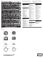
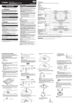
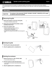
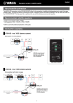
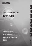
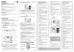
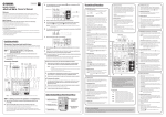
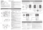
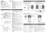
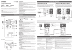
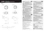
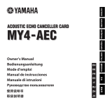
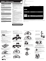
EN
Ceiling Speaker
ZE88180
English
Owner’s Manual
PRECAUTIONS
PLEASE READ CAREFULLY BEFORE PROCEEDING
* Please keep this manual in a safe place for future reference.
WARNING
Always follow the basic precautions listed below to avoid the possibility of
serious injury or even death from electrical shock, short-circuiting,
damages, fire or other hazards. These precautions include, but are not
limited to, the following:
Do not open
• This device contains no user-serviceable parts. Do not open the device or
attempt to disassemble the internal parts or modify them in any way. If it
should appear to be malfunctioning, discontinue use immediately and have it
inspected by qualified Yamaha service personnel.
Water warning
• Do not expose the device to rain, use it near water or in damp or wet
conditions, or place on it any containers (such as vases, bottles or glasses)
containing liquids which might spill into any openings. If any liquid such as
water seeps into the device, have the device inspected by qualified Yamaha
service personnel.
CAUTION
Always follow the basic precautions listed below to avoid the possibility of
physical injury to you or others, or damage to the device or other property.
These precautions include, but are not limited to, the following:
Location
• Do not place the device in an unstable position where it might accidentally fall
over.
• Do not place the device in a location where it may come into contact with
corrosive gases or salt air. Doing so may result in malfunction.
• Construction work should be carried out in accordance with constructionrelated law and always by a professional constructor. If the device installation
requires construction work, make sure to observe the following precautions.
- Choose mounting hardware and an installation location that can support the
weight of the device.
- Avoid locations that are exposed to constant vibration.
- Use the required tools to install the device.
- Inspect the device periodically.
Connections
• Before connecting the device to a power amplifier, turn off the power for all
devices. Before turning the power on or off for all devices, set all volume
levels to minimum.
• Use only speaker cables for connecting speakers to the speaker jacks. Use of
other types of cables may result in fire.
Maintenance
• Do not wipe the outer packaging with benzine, thinner, or synthetic detergent
and do not use electrical contact cleaner. These may damage the outer
packaging and dissolve the parts.
Handling caution
• Do not insert your fingers or hands in openings on the device.
• Do not operate the device if the sound is distorting. Prolonged use in this
condition could cause overheating and result in fire.
• When choosing a power amplifier for use with this device, make sure that the
output power of the amplifier is lower than the power capacity of this device
(see SPECIFICATIONS).
Even if the output power of the amplifier is lower than the power capacity of
this device (PGM), use of excessive input signals resulting in clipping may
cause damage to the device.
Malfunction or fire may occur especially when the following sounds or noises
are generated:
- feedback, when using a microphone
- continuous and extreme volume sound from a musical instrument
- extreme continuous distorted sound
- noise caused by plugging/unplugging the cable while the amplifier is turned
on
NOTICE
To avoid the possibility of malfunction/damage to the product or damage to other
property, follow the notices below.
● Handling and Maintenance
• Do not place vinyl, plastic or rubber objects on the device, since this might
discolor the panel.
• When cleaning the device, use a dry and soft cloth. Do not use paint thinners,
solvents, cleaning fluids, or chemical-impregnated wiping cloths.
• Condensation can occur in the device due to rapid, drastic changes in
ambient temperature-when the device is moved from one location to another,
or air conditioning is turned on or off, for example. Using the device while
condensation is present can cause damage. If there is reason to believe that
condensation might have occurred, leave the device for several hours until
the condensation has completely dried out.
• Be sure to observe the amplifier’s rated load impedance (see
SPECIFICATIONS), particularly when connecting speakers in parallel.
Connecting an impedance load outside the amplifier’s rated range can
damage the amplifier.
• When connecting the speakers with high impedance, be sure that the total
rated input capacity of the speakers does not exceed the output power of the
amplifier.
• When using a high-impedance speaker connection, make sure the audio
signal is passed through an 80 Hz or above high-pass filter before being input
to the speakers.
• ABOUT THE PROTECTION CIRCUIT
This speaker system has an internal protection circuit that shuts off the
speaker unit when an excessive input signal is applied.
If the speaker unit emits no sound, reduce the volume level of the amplifier
immediately.
The sound will return automatically in several seconds.
• Do not swing the speaker by its carrying band.
• Do not place the speaker face down with the grille attached, as deformation of
the grille may result.
• When placing the speaker face down, always place it on a flat and smooth
surface.
• Do not touch the speaker driver unit.
UNPACKING
Unpack the contents and confirm that all the following items are included.
• Speaker × 2
• Grille × 2
• O-ring × 2
• Tile Rail × 4
• Screw × 4
• Cutout Template × 1
• Owner’s Manual (this manual)
* Speaker cable and safety wire are not included.
SPECIFICATIONS
VXC8/VXC8W
VXC6/VXC6W
2-way, Coaxial type, with Back Can, Acoustic Suspension
LF
8" (20 cm) cone driver
6-1/2" (16 cm) cone driver
HF
1" (2.5 cm) soft dome tweeter
4/5" (2 cm) soft dome tweeter
Coverage angle (500 Hz – 4 kHz on average)
100° conical
110° conical
Nominal impedance
8Ω
NOISE
90 W
75 W
Power rating
(IEC, 100h) *1
PGM
180 W
150 W
MAX
360 W
300 W
Sensitivity (1W, 1m) *2
90 dB SPL
86 dB SPL
Maximum SPL (Calculated, 1m) *3
116 dB SPL
111 dB SPL
55 Hz – 20 kHz
56 Hz – 20 kHz
Frequency range (-10 dB) *2
Crossover frequency (12 dB/Oct)
3 kHz
3.2 kHz
Connector
Euroblock (4 pin) × 1 (input: +/-, loop-thru: +/-)
Max. wire size 12 AWG (2.5 mm2)
Transformer taps
70 V
60 W, 30 W, 15 W, 7.5 W
100 V
60 W, 30 W, 15 W
Overload protection
Full-range power limiting to protect network and transducers
Magnetically shielded
No
Enclosure
Shape
Back Can
Back Can material
Steel 1 mm, Black
Baffle material
HIPS
Grille
Material
Powder coated perforated steel (t=0.6 mm)
Trim Ring: ABS
Aperture ratio: 51%
Finish
VXC8/VXC6 : Black painting (approximate value: Munsell N3)
VXC8W/VXC6W : White painting (approximate value: Munsell 5Y9/05)
Dimensions (Speaker only)
Ø325 × 258.5D mm (Ø12-13/16" × 10-3/16"D)
Ø286 × 204D mm (Ø11-1/4" × 8-1/16"D)
Net weight (Speaker only, 1 piece)
6.6 kg (14.6 lbs)
4.4 kg (9.7 lbs)
Cutout size
Ø285 mm (Ø11-1/4")
Ø247 mm (Ø9-3/4")
Required ceiling board thickness
5 mm – 35 mm
Conduit tube
up to 1/2"
Packaging
Packaged in pair
Type
Component
*1: Pink noise with 6 dB crest factor.
*2: Half-space (2π)
*3: Calculated based on power rating and sensitivity, exclusive of power compression.
Specifications and descriptions in this owner's manual are for information purposes only. Yamaha Corp. reserves the right to change or modify products or
specifications at any time without prior notice. Since specifications, equipment or options may not be the same in every locale, please check with your Yamaha
dealer.
The dimensions are shown overleaf.
● About This Manual
The illustrations as shown in this manual are for instructional purposes only, and
may appear somewhat different from those on your device.
Yamaha cannot be held responsible for damage caused by improper use or
modifications to the device.
INSTALLING THE SPEAKERS
There are two acceptable wiring methods.
Install the speakers onto the ceiling with the supplied hardware. Ensure that
the strength of the ceiling rail is sufficiently strong.
Illustrations in this manual are for the VXC6. The installation method is the
same for other models.
CAUTION
When connecting with low impedance, take note of the combined
resistance.
Pre-installation (Preparation of the Cable)
Use stranded wire for cables attached to the Euroblock connector. Strip
their insulation as shown in the figure and connect them.
About 7 mm (0.3 in.)
7 Hold the cable in the strain relief clamp, then tighten screws A and B.
Using Loop-Through Terminals
For this method, cables are connected from terminals 1 and 4 to the
subsequent speaker. If the Euroblock connector is disconnected from
a speaker, all subsequent speakers will not work. This can be useful
to identify which speaker has a problem.
From amplifier or
previous speakers
1 CUT OUT A HOLE IN THE CEILING
1 Put the supplied cutout template to the ceiling and draw a circle by
tracing it.
Make sure to use the cutout template so that hole is the correct
diameter.
2 INSTALL THE TILE RAILS AND O-RING
1 Insert the two tile rails through the cut hole and place them on the
ceiling surface within your reach. Be sure that each tile rails are
oriented as shown below.
To subsequent
speakers
To
subsequent
speakers
Euroblock
connector
NOTE
If you use a circular cutter, set the diameter with the cutout template.
2 Cut the hole by tracing the circle.
Be careful to prevent chips or powder entering your eyes while
cutting the hole.
To release the speaker from the
O-ring, press the Anti-Drop tabs.
These are located above the U
mark near the edge of the baffle’s
face.
8 Close the terminal cover and tighten the screw.
NOTE
Do not plate stranded wires by solder. Doing so will cause the wire to break.
When all the Anti-Drop tabs cross
over the O-ring, the speaker is held
temporarily.
Screw
Power
amplifier
4 FIX THE SPEAKERS ONTO THE CEILING
Speaker
Paralleling Input Terminals
For this method, cables are connected to terminals 2 and 3 of each
speaker. Since the cables are connected via Euroblock connectors,
subsequent speakers can work even if a problem occurs with a
speaker.
1 Attach the safety wire to the safety wire ring, and connect the wire to
an independent support point, such as a joist.
3 Turn the screwdriver a half turn counterclockwise to loosen the
attachment screw (located beside the U mark). This makes the
clamp easier to align in the channel.
4 Turn the screwdriver clockwise to tighten the attachment screw.
The first turn of the attachment screw aligns the clamp with the
channel. Further turns move the clamp down the channel to pull the
speaker up into the ceiling.
Safety wire ring
2 Insert the folded O-ring through the cut hole and open it in the ceiling.
Clamp
3 Secure the O-ring and tile rails with supplied two screws through
either slot of both O-ring brackets.
O-ring
From amplifier or
previous speakers
To subsequent
speakers
To
subsequent
speakers
Euroblock
connector
2 Push up the speaker slowly into the ceiling, taking care not to trap the
cable.
Power
amplifier
Tile rail
CAUTION
Always take measures to prevent the speaker from falling down.
If the safety wire is too short, prepare another wire appropriate for the
speaker weight and installation conditions. If the wire is too long,
should the speaker fall, the wire may snap as a result of too much
strain.
3 CONNECT THE WIRING TO THE CONNECTOR AND FIX
THE CABLE
4 Plug the connected Euroblock connector into the socket in the
speaker.
Illustration indicates the setting at 60 W for 100 V
line and 30 W for 70 V line.
2 Loosen the screw at the right of the terminal cover to open the
terminal cover and remove the Euroblock connector.
CAUTION
• The “X” position should not be selected. The 8Ω position should be
selected for 8Ω audio systems only. If the setting is incorrect, it may
cause malfunction of the speaker and amplifier.
• Make sure the amplifier is switched off before operating the tap selector
switch.
Euroblock connector
Terminal cover
3 After loosening the terminal screws of the Euroblock connector with a
flat-blade screwdriver, insert the cable into each terminal and tighten
the screws. Make sure that cables cannot be pulled out.
5 SET THE LINE VOLTAGE/IMPEDANCE AND POWER
Select the line voltage/impedance (100V/70V/8Ω) and power tap for 100V/
70V line distributed system, by rotating the tap selector switch on the front
side of the speaker with a flat-blade screwdriver.
Speaker
1 Pull the wiring from the amplifier through the cut hole.
CAUTION
• Do not over-tighten the attachment screw. Otherwise, the
attachment screw and clamp will break.
• Do not turn any screws other than attachment screw (located
beside the U mark). Otherwise, the speaker may fall or
malfunction.
5 Loosen the screw A of the strain relief clamp.
6 ATTACH THE GRILLE
6 Remove the screw B of the strain relief clamp.
If the cable is not to be held, remove the screw A and remove the
strain relief fitting, then proceed to step 8.
Fit the grille to the baffle front and turn it clockwise.
Anti-Drop tab
B
Euroblock connector
A
NOTE
Use a flat-blade screwdriver with a blade less than 3 mm (0.1 in.).
Less than 3 mm (0.1 in.)
CAUTION
The grille may fall down if it is attached inadequately. Attach it firmly.
For details of products, please contact your nearest Yamaha
representative or the authorized distributor listed below.
Pour plus de détails sur les produits, veuillez-vous adresser à Yamaha ou
au distributeur le plus proche de vous figurant dans la liste suivante.
NORTH AMERICA
CANADA
Yamaha Canada Music Ltd.
135 Milner Avenue, Toronto, Ontario,
M1S 3R1, Canada
Tel: 416-298-1311
U.S.A.
Yamaha Corporation of America
6600 Orangethorpe Avenue, Buena Park, CA 90620,
U.S.A.
Tel: 714-522-9011
CENTRAL & SOUTH AMERICA
MEXICO
Yamaha de México, S.A. de C.V.
Av. Insurgentes Sur 1647 Piso 9, Col. San José
Insurgentes, Delegación Benito Juárez, México,
D.F., C.P. 03900
Tel: 55-5804-0600
BRAZIL
Yamaha Musical do Brasil Ltda.
Rua Joaquim Floriano, 913 - 4º andar, Itaim Bibi,
CEP 04534-013 São Paulo, SP. BRAZIL
Tel: 011-3704-1377
ARGENTINA
Yamaha Music Latin America, S.A.,
Sucursal Argentina
Olga Cossettini 1553, Piso 4 Norte,
Madero Este-C1107CEK
Buenos Aires, Argentina
Tel: 011-4119-7000
VENEZUELA
Yamaha Music Latin America, S.A.,
Sucursal Venezuela
C.C. Manzanares Plaza P4
Ofic. 0401- Manzanares-Baruta
Caracas Venezuela
Tel: 58-212-943-1877
PANAMA AND OTHER LATIN
AMERICAN COUNTRIES/
CARIBBEAN COUNTRIES
Yamaha Music Latin America, S.A.
Torre Banco General, Piso No.7, Marbella,
Calle 47 y Aquilino de la Guardia,
Ciudad de Panamá, República de Panamá
Tel: +507-269-5311
EUROPE
THE UNITED KINGDOM/IRELAND
Yamaha Music Europe GmbH (UK)
Sherbourne Drive, Tilbrook, Milton Keynes,
MK7 8BL, U.K.
Tel: 01908-366700
Die Einzelheiten zu Produkten sind bei Ihrer unten aufgeführten
Niederlassung und bei Yamaha Vertragshändlern in den jeweiligen
Bestimmungsländern erhältlich.
Para detalles sobre productos, contacte su tienda Yamaha más
cercana o el distribuidor autorizado que se lista debajo.
MALTA
Olimpus Music Ltd.
The Emporium, Level 3, St. Louis Street Msida
MSD06
Tel: 02133-2144
NETHERLANDS/BELGIUM/
LUXEMBOURG
Yamaha Music Europe Branch Benelux
Clarissenhof 5-b, 4133 AB Vianen, Netherlands
Tel: 0347-358 040
FRANCE
Yamaha Music Europe
7 rue Ambroise Croizat, Zone d'activites Pariest,
77183 Croissy-Beaubourg, France
Tel: 01-64-61-4000
ITALY
Yamaha Music Europe GmbH, Branch Italy
Viale Italia 88, 20020 Lainate (Milano), Italy
Tel: 02-935-771
SPAIN/PORTUGAL
Yamaha Music Europe GmbH Ibérica, Sucursal
en España
Ctra. de la Coruna km. 17,200, 28231
Las Rozas (Madrid), Spain
Tel: +34-91-639-88-88
GREECE
Philippos Nakas S.A. The Music House
147 Skiathou Street, 112-55 Athens, Greece
Tel: 01-228 2160
SWEDEN/FINLAND/ICELAND
Yamaha Music Europe GmbH Germany filial
Scandinavia
J. A. Wettergrensgata 1, Box 30053
S-400 43 Göteborg, Sweden
Tel: +46 31 89 34 00
DENMARK
Yamaha Music Europe GmbH, Tyskland – filial
Denmark
Generatorvej 6A, DK-2730 Herlev, Denmark
Tel: 44 92 49 00
NORWAY
Yamaha Music Europe GmbH Germany Norwegian Branch
Grini Næringspark 1, N-1361 Østerås, Norway
Tel: 67 16 78 00
RUSSIA
Yamaha Music (Russia) LLC.
Room 37, bld. 7, Kievskaya street, Moscow,
121059, Russia
Tel: 495 626 5005
OTHER EUROPEAN COUNTRIES
Yamaha Music Europe GmbH
Siemensstraße 22-34, 25462 Rellingen, Germany
Tel: +49-4101-3030
GERMANY
Yamaha Music Europe GmbH
Siemensstraße 22-34, 25462 Rellingen, Germany
Tel: 04101-3030
SWITZERLAND/LIECHTENSTEIN
Yamaha Music Europe GmbH
Branch Switzerland in Zürich
Seefeldstrasse 94, 8008 Zürich, Switzerland
Tel: 044-387-8080
AUSTRIA/BULGARIA
Yamaha Music Europe GmbH Branch Austria
Schleiergasse 20, A-1100 Wien, Austria
Tel: 01-60203900
CZECH REPUBLIC/HUNGARY/
ROMANIA/SLOVAKIA/SLOVENIA
Yamaha Music Europe GmbH
Branch Austria (Central Eastern Europe Office)
Schleiergasse 20, A-1100 Wien, Austria
Tel: 01-60203900
POLAND/LITHUANIA/LATVIA/ESTONIA
Yamaha Music Europe GmbH
Branch Poland Office
ul. Wrotkowa 14 02-553 Warsaw, Poland
Tel: 022-500-2925
PA36
ASIA
THE PEOPLE’S REPUBLIC OF CHINA
Yamaha Music & Electronics (China) Co.,Ltd.
2F, Yunhedasha, 1818 Xinzha-lu, Jingan-qu,
Shanghai, China
Tel: 021-6247-2211
INDIA
Yamaha Music India Pvt. Ltd.
Spazedge building, Ground Floor, Tower A, Sector
47, Gurgaon- Sohna Road, Gurgaon, Haryana, India
Tel: 0124-485-3300
INDONESIA
PT. Yamaha Musik Indonesia (Distributor)
Yamaha Music Center Bldg. Jalan Jend. Gatot
Subroto Kav. 4, Jakarta 12930, Indonesia
Tel: 021-520-2577
KOREA
Yamaha Music Korea Ltd.
8F, 9F, Dongsung Bldg. 158-9 Samsung-Dong,
Kangnam-Gu, Seoul, Korea
Tel: 02-3467-3300
MALAYSIA
Yamaha Music (Malaysia) Sdn., Bhd.
No.8, Jalan Perbandaran, Kelana Jaya, 47301
Petaling Jaya, Selangor, Malaysia
Tel: 03-78030900
SINGAPORE
Yamaha Music (Asia) Private Limited
Block 202 Hougang Street 21, #02-00,
Singapore 530202, Singapore
Tel: 65-6747-4374
TAIWAN
Yamaha Music & Electronics Taiwan Co.,Ltd.
3F, No.6, Section 2 Nan-Jing East Road, Taipei,
Taiwan R.O.C.
Tel: 02-2511-8688
THAILAND
Siam Music Yamaha Co., Ltd.
3, 4, 15 and 16th floor, Siam Motors Building,
891/1 Rama 1 Road, Wangmai,
Pathumwan, Bangkok 10330, Thailand
Tel: 02-215-2622
VIETNAM
Yamaha Music Vietnam Company Limited
15th Floor, Nam A Bank Tower, 201-203 Cach
Mang Thang Tam St., Ward 4, Dist.3,
Ho Chi Minh City, Vietnam
Tel: +84-8-3818-1122
OTHER ASIAN COUNTRIES
Yamaha Corporation
Sales & Marketing Division
Nakazawa-cho 10-1, Naka-ku, Hamamatsu,
Japan 430-8650
Tel: +81-53-460-2312
AFRICA
OCEANIA
Yamaha Music Gulf FZE
Office JAFZA 16-512, P.O.Box 17328,
Jebel Ali - Dubai, UAE
Tel: +971-4-881-5868
MIDDLE EAST
TURKEY
Yamaha Music Europe GmbH
Merkezi Almanya Türkiye İstanbul Şubesi
Maslak Meydan Sokak No:5 Spring Giz Plaza
Bağ?ms?z Böl. No:3, 34398 Şişli İstanbul
Tel: +90-212-999-8010
AUSTRALIA
Yamaha Music Australia Pty. Ltd.
Level 1, 99 Queensbridge Street, Southbank,
Victoria 3006, Australia
Tel: 3-9693-5111
COUNTRIES AND TRUST
TERRITORIES IN PACIFIC OCEAN
Yamaha Corporation
Sales & Marketing Division
Nakazawa-cho 10-1, Naka-ku, Hamamatsu,
Japan 430-8650
Tel: +81-53-460-2312
CYPRUS
Yamaha Music Europe GmbH
Siemensstraße 22-34, 25462 Rellingen, Germany
Tel: 04101-3030
OTHER COUNTRIES
Yamaha Music Gulf FZE
Office JAFZA 16-512, P.O.Box 17328,
Jebel Ali - Dubai, U.A.E
Tel: +971-4-881-5868
HEAD OFFICE Yamaha Corporation, Audio Products Sales and Marketing Division
Nakazawa-cho 10-1, Naka-ku, Hamamatsu, Japan 430-8650
DIMENSIONS
Unit: mm
VXC8/VXC8W
258.5
241
204
189
325
286
VXC6/VXC6W
286
325
O-ring
VXC8/VXC8W
VXC6/VXC6W
315
353
213.5
194.5
85
85
Ø342
Ø304
Ø282
Ø244
Tile Rail
608
38
644
32
28
Yamaha Pro Audio global web site
http://www.yamahaproaudio.com/
Yamaha Manual Library
http://www.yamaha.co.jp/manual/
C.S.G. PA Development Division
© 2013 Yamaha Corporation
310YKCR-B0
Printed in Indonesia