1
OWNER'S
MANUAL
CAUTION
RISK OF ELECTRICSHOCK
\
DONOTOPEN
1
2
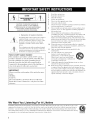
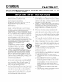
Read these instructions.
3
4
5
Heed all warnings.
Follow all instructions.
6
CAUTION:
TO REDUCE THE RISK OF
ELECTRIC SHOCK, DO NOT REMOVE
COVER (OR BACK). NO USER-SERVICEABLE
PARTS INSIDE. REFER SERVICING TO
QUALIFIED SERVICE PERSONNEL.
•
Explanation
Do not block any ventilation openings. Install in accordance
with the manuli_cturer's instructions.
8
Do not install near any heat sources such as radiators, heat
registers, stoves, or uther apparatus (including amplifiers)
that produce heat.
Do not delcat the safety purpose of the polarized ur
grounding-type plug. A polarized plug has two blades with
one wider than the other. A gruunding type plug has two
blades and a third grounding prong. The wide blade or the
third pruug are provided for your safety. If the provided plug
does not fit intu your outlet, consult an electrician for
replacement uf the obsolete outlet.
10
Protect the power culal from being walked un or pinched
particularly at plugs, convenience receptacles, and the point
where they exit Ii'om the apparatus.
Only use attachments/accessuries
specified by the
manufacturer.
persolls,
The exclanlation point within an equihaeral triangle
is intended to alert you to the presence of important
ol?eratingand maintenance (_lvicing) instructions in
' the literature acc°mpanying the al)pliance
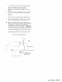
Note to CATV system
11
12
installer:
This reminder is provided to call the CATV system
installer's attention to Article 820-40 of the NEC that
provides
guidelines
for proper grounding
and, in
that the cable
shall be
particuhtr,
specifies
connected
to the grounding
system
ground
of the building,
13
as
14
close to the point of cable entry as practical.
IMPORTANT
Please record the serial nnmber of tiffs unit in the space
below.
MODEL:
Serial No.:
The serial number is located on the rear of the unit.
Retain this Owner's Manual in a sale place for future
reference.
We Want You Listening
Do not use this apparatus near water.
Clean only with dry cloth.
7
of Graphical Symbols
The lightning flash with arrowheztdsymbol,within an
equilateral triangle, is intended l() alert you to the
presence o1uninsulaled "dangerous voltage" within
the product's erich)sure thai l]lay be of sufficient
magnitude to constitute a risk o1electric shock l()
Keep these iustructiuus.
Use only with the cart. stand, tripod,
bracket, or table specified by the
manuli_cturer, or sold with the apparatus.
When a cart is used. use caution when
moving the cart/apparatus cumbiuation to
avoid ii!jury frum tip-over.
Unplug this apparatus during lightning storms or when
unused for lung periuds of time.
Relcr all servicing to qualified service persunneh Servicing
is required when the apparatus has been damaged in any
way, such as power-supply cord or plug is damaged, liquid
has been spilled or o[_iects have fallen into the apparatus, the
apparatus has been exposed to rain or moisture, does nut
operate normally, ur has been dropped.
For A Lifetime
YAMAHA :rod the Electronic Industries Assuciation's Uousumer Electronics Group want >ou tu get the must out ul your
equipment by playing it at a sale level. One that lets the sound cume through loud and clear without annoying blaring or
distortion
and. most importantly, without affecting yuur sensitive hearing. Since hearing damage from loud sounds is
often undetectable until it is too late, YAMAHA and the Electronic Induslries Associatiuu's Cunsumer Electronics Group
recommend you to avoid prolonged exposure from excessive vohlme levels.
LISTENING
FCC INFORMATION
1
IMPORTANT
INIT!
NOTI(E:
DO NOT MODIFY
THIS
(for US customers)
Complimu:e with FCC regulatkms dues not guarantee that
interference will not occur in all installations. If this
This product, when installed as indicated in the
instructions contained in this m:mual, meets FCC
product is found to he the source of interlerence, which
c:m be determined by turning the unit "OFF" and "ON".
requirmuents. Modifications not expressly approved by
Yamaha may w_id your authority, granted by the FCC. to
please try to eliminate the problem by using one of the
following measures:
use the product.
Relocate either this product or the device that is being
IMPORTANT:
When comlecting this product to
afli:cted by the interference.
accessories and/or another product use only high quality
shielded cables. Cable/s supplied with this product MUST
be used. Follow all installation instructions. Failure to
li_llow instructions could void your FCC authorization
to
Utilize power outlets that are on different branch (circuit
breaker or fllse) circuits or install AC line filter/s.
In the case of radio or TV interference, relocate/reorient
the antenna. If the antmma lead-in is 300 ohm ribbon lead.
use this product in the USA.
NOTE: This product has been tested and found to comply
with the requirements listed in FCC Regulations. Part 15
for Class "B" digital devices. Compliance with these
requirements provides a reasonable level of assurance that
your use uf this product in a residential environment will
not result in harmful interference with other electronic
devices.
change the lead-in to coaxial type cable.
This equipment generatesklses radio frequencies and. if
not installed and used according to the instructions found
in the users manual, may cause interl'erence harmful to the
The above statements apply ONLY to those products
distributed by Yamaha (orporation of America or its
subsidiaries.
operation of other electronic devices.
If these corrective measures do not produce satisfactory
results, please contact the local retailer authorized to
distribute this type of product. If you can not locate the
appropriate retailer, please contact Yamaha Electronics
Corp.. U.S.A. 6660 Orangethorpe Ave. Buena Park. CA
9(1620.
1 Toassure
thefinest
performance,
please
read
thismanual
carefully.
Keep
itinasafe
place
forfuture
reference.
2 Install
thissound
system
inawellventilated,
cool.
dry,
clean
placeaway
t'rom direct sunlight, heat sources, vibration.
dust. moisture, and/or cold. Allow ventilation space of at least
30 cm on the top, 20 cm on the lell and right, and 20 cm on
the back of this unit.
3
Locate this unit away from other electrical appliances, motors.
or transformers to avoid humming sounds.
4
Do not expose this unit to sudden temperature changes from
cold to hot. attd do not locate this unit in art mwironment with
high humidity (i.e. a room with a humidifier) to prevent
condensation inside this unit. which may cause an electrical
shock, fire. damage to this unit. and/or personal injury.
5
Avoid installing this unit where loreigu ohjects may fall onto
this unit and/or this unit may be exposed to liquid dripping or
splashing. On the top of this unit. do not place:
Other components, as they may cause damage and/or
discoloration on the surface of this unit.
Burning ot_jects (i.e. candles), as they may cause fre.
damage to this trait, attd/or personal injury.
Containers with liquid in them. as they may fall and liquid
may cause electrical shock to the user and/or damage to
this unit.
15 When not plamting to use this unit f_r long periods of time
(i.e. vacation), disconnect the AC power plug from the wall
outlet.
16 Install this unit near the AC outlet and where the AC power
plug can be reached easily.
17 Be sure to read the "TROUBLESHOOTING"
section on
common operating errors before concluding that this unit is
faulty.
18 Betore moving this unit, press MASTER ON/OFF to release it
outward to the OFF position, and disconnect the AC power
plug l}om the wall outlet.
19 VOLTAGE SELECTOR (Asia and General models only)
The VOLTAGE SELECTOR on the rear panel of this unit
must be set for your local main voltage BEFORE plugging
into the AC main supply. Voltages are:
General model ............. AC 110/120/2201230 240 V. 50160 Hz
Asia model ................................ AC 2201230 240 V. 50160 Hz
WARNING
TO REDUCE
THE RISK OF FIRE OR ELECTRIC
SHOCK, DO NOT EXPOSE
OR MOISTURE.
THIS
UNIT TO RAIN
As long as this unit is connected to the AC wall outlet,
it is not disconnected from the AC power source even
if you turn off this unit by MASTER ON/OFF, or
MAIN ZONE ON/OFF and ZONE 2 ON/OFF. In this
6
Do not cover this unit with a newspaper, tablecloth, curtain.
etc. in order not to obstruct heat radiation. If the temperature
inside this unit rises, it may cause fire. damage to this unit.
and/or personal il_jnry.
7
Do not plug in this unit to a wall outlet tmtil all connections
are complete.
state, this unit is designed to consume a very small
quantity of power.
8
Do not operate this unit upside-down. It may overheat.
possibly causing damage.
Do not use torce on switches, knobs and/or cords.
FOR CANADIAN
9
10 When discommcting the power cable from the wall outlet.
grasp the plug; do not pull the cable.
11 Do not clean this trait with chemical solvents: this might
damage the finish. Use a clean, dry cloth.
12 Only voltage specified on this unit must be used. Using this
unit with a higher voltage than specified is dangerous and may
cause fire. damage to this unit. attd/or personal injury.
YAMAHA will not be held responsible for any damage
resulting fi'om use of this unit with a voltage other than
specified.
13 To prevent damage by lightning, keep the power cord and
outdoor antennas disconnected from a wall outlet or the unit
during a lightning storm.
14 Do not attempt to modil} or fix this unit. Contact qualified
YAMAHA service personnel when any service is needed. The
cabinet should never be opened fl_r arty reasons.
iii
CUSTOMERS
To prevent electric shock, match wide blade of plug to
wide slot and fully insert.
This Class B digital apparatus complies with Canadian
ICES-003.
POUR LES CONSOMMATEURS CANADIENS
Pour _viter les chocs _lectriques, introduire la lame la
plus large de la fiche dans la borne correspondante de
la prise et pousser jusqu'an fond.
Cet appareil numdrique de la classe Best conforme _
la norme NMB-003 du Canada.
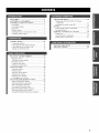
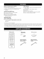
FEATURES .............................................................
SUPPLIED ACCESSORIES
.................................
CONTROLS
AND FUNCTIONS
.........................
Front panel .................................................................
Front panel display ....................................................
Rear panel ..................................................................
Remote control ...........................................................
2
2
3
ADVANCED
SETIP ............................................
Changing the ADVANCED SETUP menu
parameters ...........................................................
Switching the remote control ID .............................
ZONE 2 ..................................................................
3
5
6
7
!
Comlecting
Comlecting
Coralecting
Turning on
PLAYING
..................................................
speakers ................................................
the AM and FM antennas .....................
the power supply cord ..........................
and off this unit .....................................
AND RECORDING
10
11
12
14
14
..........................
15
Playing a source .......................................................
Adjusting the tonal quality .......................................
Recording a sottrce ..................................................
Using the sleep timer ...............................................
Muting the sound output ..........................................
FM/AM T[ NING .................................................
15
16
17
18
19
20
Automatic tuning .....................................................
Manual ttming ..........................................................
Automatic preset ttming ...........................................
Manual preset ttming ...............................................
Selecting preset stations ...........................................
Exchanging preset stations ......................................
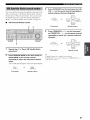
XM SATELLITE
RADIO T[ NING ..................
\_lat is XM Satellite Radio'? ...................................
XM Satellite Radio connections ..............................
XM Satellite Radio functions ..................................
20
21
22
24
25
25
26
26
26
27
Activating XM Satellite Radio ................................ 29
Basic XM Satellite Radio operations ....................... 30
XM Satellite Radio search modes ............................ 31
Setting XM Satellite Radio preset channels ............ 33
35
36
37
Connecting the Zone 2 components ........................ 37
Controlling Zone 2 ...................................................
38
REMOTE
CONTROL
FEAT[ RES ................... 39
Control area .............................................................
39
Installing batteries in the remote control ................... 9
Using the remote control ...........................................
9
CONNECTIONS
35
Controlling other components .................................
Setting remote control codes ...................................
40
41
!i
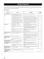
TROUBLESHOOTING
.......................................
SPECIFICATIONS
...............................................
42
45
Built-in
2-channel
II, Minimum
power
RMS
output
Other
amplifier
power
II, PURE
source
75 W + 75 W (8 _Q), 0.04% THD, 20 Hz to 20 kHz
II, Highly
dynamic
power, low impedance
drive
button
variable
used to reproduce
loudness
the purest
control
II, Sleep timer
Sophisticated
AM/FM
II, 40-station
random
II, Automatic
preset
II, Preset
station
II, Radio
Data System
access
preset
tuning
control
capability
I_ Zone 2 remote
control
II, Zone 2 custom
installation
(sold separately)
capability
facility
tuning
capability
tuning
capability
Radio tuning
capability
only)
Radio
model
II, XM Satellite
I_ Remote
tuner
exchanging
model
XM Satellite
(U.S.A.
DIRECT
sol.ll_.d
I_ Continuously
capability
(Europe
features
only)
Connect-and-Plaf
Mdigital
antenna
using the XM
accessory
(sold
separately)
• -"_;_'indicates a tip for your operation.
• Some operations can be performed by using either the buttons on the front panel of this trait or those on the remote control. In case the
button names differ between this unit and the remote control, the names of the buttons on the remote control are given in parentheses.
• This manual is printed prior to production. Design and specifications are subject to change in part as a result of improvements, etc. In
case of differences between the manual and the product, the product has priority.
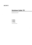
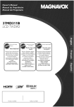
Please
check that you received
Remote control
all of the following
parts.
Batteries (x2)
(AA, R6, UM-3)
AM loop antenna
OOOO
5D_do
O_O_
_OO
@NNAHA
Indoor FM antenna
(U.S.A., Canada and
General models)
Indoor FM antenna
(Europe and Australia
models)
f_....
_
_FI
....
(U.S.A.
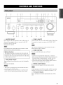
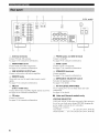
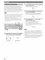
@ MASTER
Press inward
this unit. Press
position
ON/OFF
to the ON position
again to release
to turn on the power
it outward
of
to the OFF
to turn off this unit.
model)
@ ZONE 2 ON/OFF
Turns on Zone 2 or set it to the standby anode. When Zone
2 is turned on, signals are output at the ZONE 2 OUT
jacks.
See page 14 for details.
Even when this unit is turned ofi2 this unit consumes a small
amount of power to preserve the memo13".
Memory
back-up
The memory
back-up
from being lost. However,
ZONE
@
ZONE
CONTROL
Press to control
circuit
prevents
the input source
of Zone 2.
the stored data
the stored data will be lost if
the power cord is disconnected
for more than one week.
@ MAIN
This switch is operational only when MASTER ON/OFF is
pressed inward to the ON position.
from the AC wall outlet
ON/OFF
Turns on Main Zone of this unit or sets it to the standby
anode.
See page 14 for details.
• This button is operational only when Zone 2 is turned on.
• When you press this button, the ZONE 2 indicator flashes in the
front panel display for approximately 5 seconds. Select the
inpm soarce of Zone 2 while the indicator is flashing.
• You can select the preset station or channel when TLrNER or
XM is selected as the input source of Zone 2.
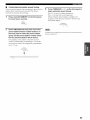
@
Remote
Receives
control
infrared
sensor
signals
from the remote
control.
• This switch is operational only when MASTER ON/OFF is
pressed inward to the ON position.
• In the standby mode. this trait consmnes a small amount of
power to receive infrared signals from the remote control.
Switch the remote control ID between ID1 and ID2 when using
multiple YAMAHA receivers or amplifiers (see pages 35, 36).
@
Front
Shows
unit.
panel
information
display
about the operational
status of this
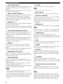
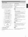
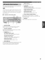
K_Ie]dll;{e]l_lF_qdleJ:llld[Bil[e]d_
@
EDIT,
SEARCH
Exchanges
other when TUNER
the input source
FM/AM,
of two preset stations
is selected
page 25).
Switches between
@
MODE
the assignment
search
with each
as the input source
modes
(see
when XM is selected
as
(see page 29).
Selects
Switches the reception band between AM and FM when
TUNER is selected as the input source (see page 20).
Shows
the reception
level of the XM Connect-and-Play
digital
antenna
separately)
the input source
@
selected
as
selector
the input source you want to listen to or watch.
AIBICIDIE,
Selects
CATEGORY
the preset
station
group (A to E) when TUNER
is
as the input source (see page 23).
Switches between channel categories
or selects the preset
channel group when XM is selected as the input source
<_ / C>
the tuning
the input source
when XM is selected
@
(see page 27).
TUNING/CH
Selects
This does not affect the OUT (REC) level.
@ INPUT
XM ANT (ANTENNA)
(sold
@ VOLUME
Increases or decreases the sound output level.
(see page 31).
frequency
when TUNER
is selected
as
(see page 20).
Searches for a radio channel or selects the preset channel
number when XM is selected as the input source (see page
@
PHONES
Outputs
jack
audio Ibr private
listening
with your headphones.
27).
Press SPEAKERS
@ TUN (TUNING)
MODE/DISP
(DISPLAY)
before you connect
AiB so that the SP AiB indicators
your headphones
to the PHONES
turn off
jack.
Switches
indicator
the tuning mode between automatic (the AUTO
turns on as a result) and manual (the AUTO
@
indicator
turns offas
Turns on or off the speaker set connected to the
SPEAKERS
A and/or SPEAKERS
B terminals on the rear
a result)
the input source.
Switches the XM Satellite
when TUNER
Radio infommtion
is selected
shown in the
front panel display between channel number name,
category and artist name/song
title when XM is selected
the input source
@
as
as
(see page 30).
in the system
as the input source
PURE
DIRECT
memory
and indicator
The indicator
possible
it lights up when this function
MONITOR
you to listen to the sound played
component
connected
to the MDiTAPE
back on the
jacks
panel of this unit.
When the tape deck is used lbr recording,
monitor
the low frequency
a flat response
response.
(see page
The 0
16).
or decreases
produces
the high frequency
a flat response
(see page
response.
The 0
16).
BALANCE
speaker
locations
or listening
room conditions
(see page
16).
on (see page 16).
MD/TAPE
Allows
or decreases
produces
Adjusts the sound output balance of the left and right
speakers to compensate
for sound imbalances
caused by
sound.
is turned
(see
TREBLE
Increases
@
you to listen to a source in the purest
above
is pressed
when XM is
(see page 33).
Allows
@
@
position
a radio channel
button
@ BASS
position
page 22).
@
panel each time the corresponding
Increases
Stores a station in the system memory (see page 24).
Sets this unit to the automatic preset tuning mode (see
selected
A/B
page 15).
MEMORY
Stores
SPEAKERS
the sound being
The MDiTAPE
MON
on the rear
you can also
recorded.
indicator
lights up when this function
in the front panel display
is turned
@ LOUDNESS
Retains a full tonal range at any volume level to
compensate for the human ears' loss of sensitivity to high
and low-frequency ranges at a low volume level (see page
16).
on.
@ Preset station/channel number buttons
(1 to 8)
Selects the preset station number (1 to 8) directly when
TUNER or XM is selected as the input source (see page
25).
• When this function is on (the indicator lights up), MDiTAPE
cannot be selected with the INPUT selector.
• To listen to the source selected with the INPUT selector, press
again to turn off the function (the indicator turns off as a result).
• When MD TAPE is selected with the INPUT selector, this
fm_ction will not turn on even if MDiTAPE MONITOR is
pressed.
The XM Satellite Radio features (XM ANT, CH. SEARCH
MODE, DISP, CATEGORY. MEMORY and the preset channel
number buttons) are only applicable to the U.S.A. model and are
operational only when XM is selected as the input source. For
details, see "XM SATELLITE RADIO TLLNING" on page 26.
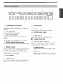
_e]dll;{e]J_'f_qdlel_lJd[e_Jl[e]d[,
@ SP (SPEAKERS)
Light up according
Both indicators
selected.
@ SLEEP indicator
A/B indicators
to the set of speakers
Lights up when the sleep timer is turned on.
selected.
light up when both sets of speakers
are
@ MUTE indicator
Flashes while the MUTE function is turned on.
@ ZONE 2 indicator
@ Multi-information display
Shows information when adjusting or changing settings.
Lights up when Zone 2 is turned on.
@ Input source indicators
@ TUNED indicator
Light up when this unit is in the corresponding mode.
Lights up when this unit is tuned into a station.
•
Europe
model
only
The XM indicator is only applicable to the U.S.A. model.
@ Radio Data System indicators
@ MD/TAPE
Lights
up while
MON
(MONITOR)
indicator
the MD TAPE monitor
function
is turned
Oll.
@
MEMORY
Flashes
indicator
for approximately
the front panel is pressed.
is flashing,
memory
number
PTY HOLD indicator
5 seconds
alter MEMORY
While the MEMORY
store the displayed
by using A/B/C/D/E
buttons
The box-shaped indicator beside the name of each Radio
Data System mode lights up when the corresponding
Radio Data System mode is selected.
station
on
indicator
Lights up while searching for stations in the PTY
SEEK mode.
in the system
and one of the preset station
EON indicator
Lights
on the front panel.
up when the Radio
offers the EON data service
@ AUTO
Lights
@
indicator
up when this unit is in the autolnatic
STEREO
tuning
mode.
indicator
Lights up vvhen this unit is receiving a strong signal for an
FM stereo broadcast while the AUTO indicator is lit.
Data Systenl
station
is being received.
that
(U.S.A.
model
{7;x]
i!..... i
@ Antenna terminals
Connect FM and AM antennas.
@ PHONO jacks and GND terminal
Connect a turntable.
See page 12 for connections information.
See page 10 for connection information.
@ AUDIO/VIDEO jacks
Connect audio and video components.
See page 10 for connection information.
@ ZONE 2 jacks
Connect a Zone 2 component.
See page 37 for connection information.
@ SUB WOOFER OUTPUT jack
Connect a subwoofer with built-in amplifier.
@ SPEAKERS terminals
Connect speakers.
See page 11 for connection information.
@ REMOTE jacks
These.jacks are used to input output remote control
signals.
See page 37 for connection information.
@ IMPEDANCE SELECTOR switch
Switches the impedance setting.
See page 11 for details.
@ XM jack
(U.S.A. model only)
Connect XM Connect-and-Play digital antenna accesso W.
See page 26 for connection information.
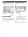
@ AC OUTLET(S) (SWITCHED)
Use to supply power to your other audio and video
components.
See page 14 for details.
@ CD jacks
Connect a CD player.
See page 10 for connection information.
•
Asia and General models only
VOLTAGE
SELECTOR
VOLTAGE
SELECTOR
on the rear panel of this unit must
be set for your local main voltage
power
supply
Voltages are as follows:
Asia model .........................
General
BEFORE
plugging
the
cord into the AC wall outlet.
AC 220/230
model ...... AC 110/120/220/230
240 V, 50/60 Hz
240 V, 50/60 Hz
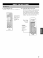
_O]_TII;{O]Jk'JF:hqlI_IJ_T[elI[O]_Tg
This section
remote
describes
control
components
The functions
of the buttons
buttons
operate
on those
"REMOTE
CONTROL
components.
manuals
your other
using this remote
FEATURES"
Refer
for details.
@
Numeric
buttons
Select the preset
are the same as those of the
instruction
other components
on the
or other manufacturers.
used to control
components
those components'
of each button
this unit or other
made by YAMAHA
audio and video
con'esponding
the function
used to control
selected
station
number
(I to 8) when TUNER
is
when XM is selected
as
as the input source.
Select the preset
channel
number
the input source.
to
To
control,
see
on page 39.
@
BAND
Switches
to the previously
AM) when TUNER
used reception
is selected
band (FM or
as the input source.
0}
..............
:?;
The frequency of the previously received station is autoznatically
recalled.
............
:g;,
@ A-E/CAT.
Selects
(CATEGORY)
the preset
is selected
as the input source
Switches
preset
between
channel
o<9)
the input source
......
_10_
PRESET/CH
Selects
channel
(see page 25).
categories
or selects
the
group (A to E) when XM is selected
as
(see page 31).
,t", / v
the preset
TI__ER
</ >
station group (A to E) when TUNER
is selected
station
number
(1 to 8) when
as the input source
(see page 25).
Searches for a radio channel or selects the preset
channel number (1 to 8) when XM is selected as the
,,<}
input source (see page 29).
@
MEMORY
Stores a radio channel
.........
84"_
selected
@
in the system
memory
when XM is
as the input source (see page 33).
STANDBY
Sets this unit to the standby
mode.
• This button is operational only when MASTER ON/OFF on the
front panel is pressed inward to the ON position.
• In the standby mode, this trait consnmes a small amount of
power to receive infrared signals from the remote control.
• This bntton does not set Zone 2 to the standby mode.
@ POWER
Turns on this unit.
@ Infrared signal transmitter
Sends infrared signals.
@ Input selector buttons
Select the desired input source and change the control area
(see page 39).
• This button is operational only when MASTER ONOFF
front panel is pressed inward to the ON position.
• This button does not turn on Zone 2.
on the
@ SPEAKERS
A/B
Turns on or off the set of speakers
SPEAKERS
A and, or SPEAKERS
connected to the
B terminals on the rear
panel of this unit when the con'esponding
pressed each time.
@
CODE
button
is
SET
Use to set up remote
control
codes
(see page 4 l).
@ SLEEP
Sets the sleep timer.
@
VOLUME
+/-
Increases or decreases
the sound
output
level.
• This does not affect the OUT (RE(?) level.
• When you press VOLUME +_ to control the sound output
level of this tulit, VOLUME on the *'rontpanel rotates.
@ MUTE
Mutes the sound output. Press again to restore the sound
output to the previous volume level (see page 19).
The sound output to Zone 2 is not muted.
@
ENT. (ENTER)
Confirms
Number
an entered
Access
channel
number
during the Direct
mode when XM is selected
as the input
source.
@
SRCH
Switches
(SEARCH)
between
MODE
the XM Satellite
(see page 31) when XM is selected
@
Radio
search modes
as the input source.
DISPLAY
Switches
the XM Satellite
front panel display
Radio infomlation
between
catego W and artist name/song
channel
number
shown in the
name,
title when XM is selected
as
the input source.
The XM Satellite Radio features (XM, SRCH MODE DISPLAY,
A-E/CAT. < / >, PRESETiCH/',
/ ",/, MEMORY and ENT.) are
only applicable to the U.S.A. model and are operational only
when XM is selected as the inpm source. For details, see "XM
SATELLITE RADIO TUNING" on page 26.
_o]_TiI;Io]ik'JF:hqel_lJ_T[ell[o]_Tt.
•
Notes on batteries
(hange all of the batteries it"the operation range of the remote contrnl decreases.
Use AA, R6, UM-3 batteries for the remote control.
Make sure that the polarities are correct. See the illustration inside the batter?," compartment of each remote control.
Remove the batteries if the remote control is not used for an extended period of time.
Do not use old batteries together with new ones.
Do not use different t)_pes of batteries (such as alkaline and manganese batteries) together. Read the packaging careffdly as these
different types of batteries may have the same shape and color.
• We strongly recommend using alkaline batteries.
• If the batteries have leaked, dispose of them immediately. Avoid touching the leaked material or letting it come into contact with
clothing, etc. Clean the battery compartment thoroughly before installing new batteries.
• Do not throw away batteries with general house waste: dispose of them correctly in accordance with your local regulations.
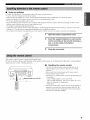
1
Open the battery compartment
cover.
Insert the supplied batteries in each remote
control according to the polarity markings (+
and -) on the inside of the battery
compartment.
3
The remote
control
transmit
Be sure to aim the remote
signal receiver
a directional
control
in Zone 2 during
directly
infrared
Close the cover back.
beam.
at the remote
control
sensor
on the front panel of this unit or on the infrared
operation.
•
Handling the remote control
• The area between the remote control and this unit (or the
in_ared signal receiver in Zone 2) nmst be clear of large
obstacles.
• Do not spill water or other liquids on the remote control.
• Do not drop the remote control.
• Do not leave or store the remote control in the following types
of conditions:
3
3Cr _\Approxirnately
6 m (19.7 ft)
places of high humidibt such as near a bath
places of high temperature, such as near a heater or a stove
places of extremely low temperatures
dusty places
• Do not expose the remote control sensor to strong lighting, in
particular, an inverter type fluorescent lamp; othenvise, the
remote control may not work properl?_ If necessary, position
this unit away t'rom direct lighting.
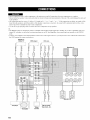
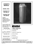
• Donotconnect
thisunitorother
components
tothemain
power
untilallconnections
between
components
arecomplete.
• Donotletthebare
speaker
wires
touch
each
other
ordonotletthem
touch
any
metal
partofthistulit.This
could
damage
thistulitand.
orthespeakers.
• Allconnections
must
becorrect:
L(left)
toL,R(right)
toR."÷" to "+" and .... to "-'. If the connections are fault?_ no sound will be
heard from the speakers, and if the polarity of the speaker connections is incorrect, the sound will be mmamral and lack bass. Also,
refer to the owner's manual lbr each of your components.
• Use the R(_A tb_pepin plug cables for audio and video components except speakers.
"4_':
• The PHONO jacks are designed to comlect a turntable with an MM or high-output MC cartridge. If you have a turntable with a lowoutpm MC cartridge, use an in-line boosting transl\mner or an MC-head amplifier when colmecting yonr turntable to the PHONO
jacks.
• Colmect ?_ur turntable to the GND temlinal to reduce noise in the signal. However, you may hear less noise without the connection to
the GND temlinal for some record players.
Digital TV,
Cable TV
DVD player
VCR, etc.
<
Speakers
Speakers
CD player
Turntable
10
Video
monitor
MD recorder,
Tape deck, etc.
B
A
•
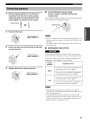
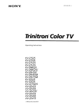
1
Remove
insulation
approximately
from
10 mm (3/8 in) of
the end of each
cable
and twist the exposed
cable
together
to prevent
speaker
wires
short
of the
circuits,
Connecting the banana plug
(U.S.A.,
Canada,
models
only)
First, tighten
Australia
and General
the knob and then insert the banana
the end of the corresponding
plug into
temfinal.
Banana plug
10 mm (3/8 in)i
I
_
_
Unscrew the knob.
Red: positive (+)
Black: negative (-)
• One or two speaker sets can be connected to this unit. If you use
only one speaker seL connect it to either the SPEAKERS A or B
terlninals.
• Use speakers with the specified impedance shown on the rear
panel of this unit.
Insert one bare wire into the hole in the side
of each terminal.
•
IMPEDANCE SELECTOR
[O'-'IIHL'o/AR
Do not slide the IMPEDAN(E
Red: positive (+)
Black: negative
(-)
Select the switch position
impedance
Switch
position
4
SELECTOR
switch while the
power of this trait is turned on, as doing so may damage the trait.
of the speakers
(left or right) according
to the
in your system.
Impedance
level
If you use one set (A or B), the impedance of
each speaker nmst be 8 _ or higher.
Tighten the knob to secure the wire.
Right
If you use two sets (A and B), the impedance
of each speaker nmst be 16 _ or higher.
Red: positive (+)
Black: negative (-)
If you use one set (A or B), the impedance of
each speaker nmst be 4 _ or higher.
Left
If you use two sets (A and B), the impedance
of each speaker nmst be 8 _ or higher.
• The Canada model cannot use two speaker sets (A and B)
simultaneously when the IMPEDAN(E
SELECTOR switch is
slid to the right position.
• If this unit ±;ailsto turn on. the IMPEDANCE SELECTOR
switch may not be fully slid to either position. If this is the case.
slide the switch all the way to either position when the power
supply to this unit is completely cut of£
11
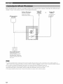
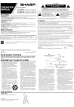
Both AM and FM indoor antennas
strength.
Connect
each antenna
are included
correctly
with this unit. In general,
to the designated
Outdoor AM antenna
Usea5 to 10mot vinylcovered
oIItdo01"S
wire
ll'onl
these antennas
should
provide
sufficient
signal
terminals.
Indoor FM
antenna
(included)
or
Outdoor FM
antenna
extended
a
window,
AM loop antenna
(included)
Ground (GND terminal)
For maxitmun
tllinill_Ulll
file antenna
good
eallh
saicty
and
interJcfence,
GND
ground,
ground is a metal
nloist earth,
connect
terminal
A good
stake
to a
earth
driven
into
• A properly ittstalled outdoor atttenna provides clearer reception than an indoor one. If you experience poor receptiott quality, an
outdoor antenna may improve the quality. Consult your nearest authorized YAMAHA dealer or service center about outdoor antennas.
• If you connect an outdoor FM antenna to this unit. do not connect the ittdoor FM antetuta to this unit.
• To mittimize interl_zrence from automobile igttition, locate the antenna as fi_r from heavy traffic as possible.
• Keep the lceder cahle or coaxial cable as short as possible. Do trot bundle or roll up excess cable.
• The antenna should be placed at least 2 meters h'om reinforced concrete walls or metal structures.
12
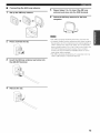
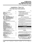
Connecting the AM loop antenna
1
Set up the
Press
5
Repeat steps 2 to 4 to insert the AM loop
antenna lead wires into the GND terminal.
6
Orient the AM loop antenna for the best
reception.
AM loop antenna.
and hold the tab.
• The AM loup antenna should be placed away l?om this unit.
• A properly installed uutdour antenna provides clearer receptiuu
than an indour one. If you experience puor reception quality, an
outdour antenna may improve the quality. It is recommended
that you should connect a 5 to 10 m of vinyl-covered wire to the
AM ANT terminal and extend it outdoors l?um a window.
Cuusult your nearest authorized YAMAHA dealer or service
center about uutdoor antennas.
• The AM luop antenna should always be cunuected, even if an
outdour AM antenna is connected to this unit.
3
Insert the AM loop antenna lead wires into
the AM ANT terminal.
4
Release the tab.
13
I[";'tfll'l_ql['h'_
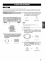
Plug the power
supply
all other connections
cord into the AC wall outlet
after
are complete.
AC power supply cord
When all connections
this unit.
are complete,
turn on the power
of
1
Press MASTER ON/OFF on the front panel
inward to the ON position to turn on the
power of this unit.
Main Zone of this unit turns on.
(General
model)
AC OUTLET(S)
•
•
AC OUTLET(S) (SWITCHED)
Australia
model
Other models
.....................................................
.......................................................
Use these outlets
to connect
your other components
the power
supply
to this unit. The outlets
power
(total power
"SPECIFICATIONS"
consumption
of components),
on page 45.
1 outlet
Press MAIN ZONE ON/OFF on the front panel or
POWER on the remote control to turn Main Zone on
cords from
again.
supply
see
mode
by pressing MAIN ZONE ON/OFF on the front panel
or STANDBY
on the remote control.
2 outlets
power to any connected
components
whenever
the power
of this unit is turned on. For information
on the maximum
You can set Main Zone of this unit to the standby
•
Press MASTER
release
unit.
it outward
ON/OFF
on the front panel again to
to the OFF position
to turn offthis
--'4:-While MASTER ON/OFF on the front panel is pressed inward to
the ON position, you can turn on Zone 2 or set it to the standby
mode independently (see page 38).
14
[e!': 1Ii tl'olAVl
Ex_eme caution should be exercised when you play back CDs encoded in DTS.
If you play back a CD encoded in DTS on a DTS-mcompatible CD player, you will only hear some unwanted noise that may damage
yottr speakers. Check whether your CD player supports CDs encoded in DTS. Also, check the sound output level of your CD player
before you play back a CD encoded in DTS.
2
Press SPEAKERS A and/or SPEAKERS B on
the front panel or on the remote control to
select speakers A and/or speakers B.
8P[AKERS
SPEAKERS
A
B
or
Front panel
5
1
2
Remote
control
•Both SPEAKERS A and B can be selected.
•Make sure that the IMPEDANCE SELECTOR switch is
correctly set (see page 11).
E
1-2
3
Play the source.
4
Rotate VOLUME on the front panel (or press
VOLUME +/-on the remote control)to
the sound output level.
-4
Rotate the INPUT selector on the front panel
(or press one of the input selector buttons on
the remote control) to select the desired
input source.
adjust
or
INPUT
Front panel
Remote
control
or
Front panel
Remote
control
Press MAIN ZONE ON/OFF on the front panel
again (or press STANDBY on the remote
control) to finish using this unit and set it to
the standby mode.
MA_N ZONE
Front panel
Remote
control
15
il'.JIF:lgdld[eiF:Idlel_l:[_e]_te]ld[J
•
Adjusting the LOUDNESS control
Retains
•
Adjusting the BALANCE control
Adjusts
the sound
speakers
output
to compensate
speaker
locations
balance
room
imbalance
high and low-fi'equency
•
Using the PURE DIRECT button
Routes input signals from your audio sources so that the
input signals bypass the BASS, TREBLE, BALANCE and
LOUDNESS controls, thus eliminating any alterations to
the audio signals and creating the purest possible sound.
1
Rotate the LOUDNESS control on the front
LOUDNESS
C©I:
,
Adjusting the BASS and TREBLE
controls
response.
or decreases
the low frequency
response.
or decreases
the high frequency
response.
;
7
Rotate VOLUME on the front panel (or press
VOLUME +/- on the remote control) to set the
sound output level to the loudest listening
level that you would listen to.
BASS
TREBLE
Increases
o_s
or
_REgLE
Remote control
Front panel
3
Rotate the LOUDNESS control until the
desired volume is obtained.
LOUDNESS
FL_
16
to
level.
panel to the FLAT position.
©
Increases
at a low volume
control set at a certain level, the inpm signals bypass the
LOUDNESS control, resulting in a sudden increase in the sound
ontput level. To prevent your ears or the speakers from being
undesirably damaged, be sure to press the PURE DIRECT button
AFTER lowering the sound output level or AFTER checking that
the LOUDNESS control is properly set.
o
the high and low frequency
ranges
If the PURE DIRECT button is turned on with the LOUDNESS
PURE _I_ECT
Adjust
level, thus
ears' loss of sensitivity
r__,llj/l'olAVl
caused by
conditions.
gALAHCE
•
at any volume
for the human
of the left and right
fbr sound
or listening
a full tonal range
compensating
'Jf__lYhV[ef__1_VeJ:l=[esre]=te]hV[J
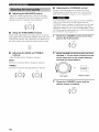
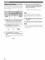
Rotate VOLUME on the front panel (or press
VOLUME +/- on the remote control) to adjust
the sound output level of the selected source
to record from.
• The VOLUME. BASS. TREBLE, BALANCE and
LOUDNESS controls and the PURE DIRECT buttons have no
effect on the source being recorded.
• Check the copyright laws in your countU to record from
records. CDs. radio, etc. Recording copyright-protected
material may infringe on cop?right laws.
or
Front panel
4
Remote
control
Begin recording on the MD recorder, the tape
deck or the VCR connected to this unit.
If the 3-head tape deck is used for recording, you can monitor the
sonnd of recording by pressing MDiTAPE MONITOR on the
front panel.
1
Play the selected source to record from.
2
Rotate the INPUT selector on the front panel
(or press one of the input selector buttons on
the remote control) to select the source you
want to record from.
INPUT
o,
Front panel
Remote
control
Note
Youcannot select any inpul source while the MDiTAPE MON
indicator in the front panel display lighls on.
17
iltJIF:lgdld[eiF:Ydlel_l:[_e]_te]ld[J
Use this feature
standby
mode
to automatically
after a certain
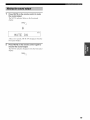
Press SLEEP repeatedly so that SLEEP OFF
appears in the front panel display.
set this unit to the
amount
of time. The sleep
SLEEP
timer is useful when you are going to sleep while this unit
is playing
or recording
a source.
The sleep timer also
automatically
turns off any external
connected to the AC OUTLETS.
....mL,= L,=L,= i
m==,m
i i
components
After a few seconds, SLEEP OFF disappears from the
front panel display, and the SLEEP indicator tums
off.
The sleep timer setting can also be canceled by pressing
STANDBY on the remote control (or MAIN ZONE O_OFF
MASTER ON/OFF on the front panel) to set this unit to the
standby mode.
• The sleep timer can only be set with the remote control.
• The sleep timer automatically turns off Zone 2. However. the
power of Zone 2 components are not turned off.
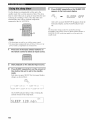
1
Press one of the input selector buttons on
the remote control to select an input source.
2
Start playback on the selected input source.
3
Press SLEEP repeatedly to set the amount of
time before this unit is set to the standby
mode.
Each time you press SLEEP, the fi'ont panel display
changes as shown below.
SLEEP
_
,=.i
iii ii ........
::::,i..]::]::jJ
?.:,::i:::{
iq:t.i"_ _> :i;L,i_i_F'9_:_iiq:i.i"_
FFF' ,:!4::ii'_:!.i'_<- :i;L,Ei_;F' _!:4::ii'_:!.i'_
The SLEEP
amount
indicator
flashes
:!!;i...,
EEF::':i.2 0
18
while
switching
the
of time for the sleep timer.
J,n
7
....
or
'$f__|¥1,v[ef__y,Vel:l_[_.io]:le]hV[J
Press MUTE on the remote control to mute
the sound output.
The MUTE indicator flashes in the front panel
display.
m'.'im i "r" m
....
¢"; L i
HLJ mE.
LJPm
After a few seconds,
l'ront panel
2
Press
resume
ON disappears
from the
display.
MUTE
on the remote
the sound
The MUTE
MUTE
"
indicator
control
again to
output.
disappears
from the front panel
display.
19
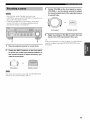
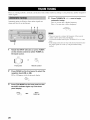
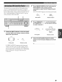
There are 2 tuning
station
Automatic
strong
methods
autonmtic
and manual.
Select either
method
according
to your preference
and the strength
of
signals.
tuning
is effective
when station
signals
Press TUNING/CH <:1/ _> once to begin
automatic tuning.
Press C> to tune into a higher frequency.
Press <:1to tune into a lower frequency.
are
and there is no interference.
243
• When you _ule into a station, the frequency of the received
station is shown in the front panel display.
• To search for another station, press TUNING CH <1 C> once
more.
• If the tuning search does not stop at the desired station because
the station signals are weak, try using the manual tuning
method.
Rotate the INPUT selector (or press TUNER
on the remote control) to select TUNER as
the input source.
INPUT
or
_
TUNER
Front panel
Press
FM/AM
Remote control
on the front
panel
to select
the
reception band (FM or AM).
FM or AM appears
in the front panel display.
FM/AM
Press TUN MODE on the front panel so that
the AUTO indicator lights up in the front
panel display.
_o,_,.p
AUTO
Lights up
20
l+tr,_Y+tllqi'/fi'P
4
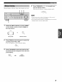
Manual tuning is effective when station signals are weak.
Press TUNING/CH <1 / c> to manually tune
into the desired station.
Hold down tile button to continue tuning search.
243
• When
you tune into a station,
the frequency
ol the received
station is shown in the front panel display.
• If you tune intoan FM station, it is automatically received in the
monattral mode to increase signal quality.
Rotate the INPUT selector (or press TUNER
on the remote control) to select TUNER as
the input source.
+NPUT
or
(C
_
TUNER
Front panel
Remote
control
Press FM/AM on the front panel to select the
reception band (FM or AM).
FM or AM appears in the front panel display.
FM/API
Press TUN MODE on the front panel so that
the AUTO indicator disappears from the front
panel display.
AUTO
+mm+++,mp
_
Disappears
21
l;jV_j_|lql'lh7
_
Press
You can use the automatic
automatically
preset tuning
store FM stations.
unit to automatically
tune into FM stations
signals
and store up to 40 (8 stations
groups,
AI to ES) of those
can then easily
preset
station
received
recall any preset
numbers
method
This fimction
to
enables
FM/AM
on the front
as the reception
this
FM appears
panel
to select
FM
band.
in the t>ont panel display.
F_AM
with strong
in each of the 5
stations
stations
in order. You
by selecting
the
where they are stored.
• Any station data stored under a preset station number is cleared
when you store a new station under that preset station number.
• If the number of received stations does not reach 40 (E8),
automalic preset tuning automatically stops once searching all
available stations are tuned into and stored.
• Only FM stations with suflicient signal strength are stored
automatically by automatic preset tuning. If the station you
want to store is weak in signal strength, try using the manual
preset tuning method.
Press and hold MEMORY on the front panel
for more than 3 seconds.
The preset station group and the MEMORY and
AUTO indicators flash in the front panel display.
Press
TUNING/CH
automatic
preset
<1/E>
Press C> to tune into higher
2
once
to begin
tuning.
frequencies.
Press <1 to tune into lower frequencies.
84
When
automatic
frequency
preset
tuning
of the last preset
is complete,
station
is shown
the
in the
front panel display.
• If TL_P'.IINGiCH<1 / C> is not pressed within approximately
seconds while the MEMORY and AUTO indicators are
1
Rotate
the INPUT
on the remote
selector
control)
(or press
to select
TUNER
TUNER.
=NPu-r
or
_)
TUNEF_
Front panel
22
Remote control
5
flashing, automatic preset ttming automatically begins from the
currently displayed frequency and proceeds toward higher
frequencies.
• Received stations are sequentially progrannned to 8 stations in
each preset station group. If 8 stations are all progrannned in a
preset station group, another 8 stations are sequentially
programmed in the next preset station group.
rigg_Yi'_|lql'lfl'[
J
•
Customized
automatic
preset tuning
You can specify a preset station group and it preset station
number from which this unit stores the FM stations
Press TUNING/CH
received by automatic preset tuning.
Press t::> to tune into higher
begin
automatic
<1 / E> on the front
panel
to
preset tuning.
frequencies.
Press <1 to tune into lower frequencies.
1
Press and hold MEMORY on the front panel
for more than 3 seconds.
When automatic
frequency
preset
tuning
of the last preset
is complete,
station
the
is shown in the
front panel display.
Press A/B/C/D/E and then press one of the
preset station/channel number buttons on
the front panel to select the preset station
group and the preset station number where
the first received station will be stored.
Automatic preset tuning stops when the received stations have all
been stored np to E8.
For example, if you select (75, the first received
station is automatically programmed to C5 and the
next received stations are sequentially programmed
to (76, (77, etc.
23
You can also manually
store up to 40 stations
each of the 5 groups,
any preset
stations
(8 stations
Press one of the preset station/channel
number buttons on the front panel to select a
preset station number (1 to 8) where you
want to store the station.
in
AI to E8). You can then easily recall
by selecting
the preset station
nmnbers
where they are stored.
2
This operation must be done within 5 seconds while the
MEMORY indicator is flashing in the front panel display.
Otherwise, the manual preset ttming process is automatically
canceled.
3
4
Repeat steps 1 to 4 in "Automatic tuning" or
in "Manual tuning" to tune into a station.
When you tune into a station, tile frequency of tile
received station is shown in the front panel display.
Press
MEMORY
The MEMORY
display
on the front
indicator
flashes
for approxinmtely
Press
AIBIC/DIE
repeatedly
in the front panel
MEMORY
_
Flashes
on the front
to select
a preset
panel
station
group
(A
to E).
The selected
preset station
panel display.
_a/ctD_e
24
Press MEMORY on the front panel to store
the station.
0
Repeat steps 1 to 5 to store other stations.
• Any station data stored under a preset station mnnber is cleared
when you store a new station under that preset station nun/ber.
• The reception mode (stereo or monaural) is stored along with
the station l]'equency.
panel.
5 seconds.
,,_E_o._
5
group is shown in the front
+Ig,_
f++llq_'If_'P
You can tune into the desired
the preset
station
mnnber
station
simply
by selecting
where it is stored.
You can exchange
the assignment
of two preset stations
with each other. The following
procedure
example
El is exchanged
another
where
preset
a preset
station
station
describes
an
with
A5.
2,4
1
2
Press A/B/C/DIE on the front panel
repeatedly (or press A-E/CAT. < / ) on the
remote control) to select a preset station
group (A to E).
Tile selected preset station group is sho'a,n in tile front
panel display.
1
Repeat steps 1 and 2 in "Selecting
preset
stations" to select a preset station El.
2
Press EDIT on the front panel.
El and the MEMORY indicator fhtsh in tire front
panel display.
MEMORY
Flashes
or
PRESET/CH
Frontpanel
Remotecontrol
Repeat
Press one of the preset station/channel
number buttons on the front panel (or
steps
1 and 2 in "Selecting
panel display.
PRESET/CH/,, / v on the remote control) to
select a preset station number (1 to 8).
Tile preset station number appears in tire front panel
display along with the reception band and the
frequency.
MEMORY
Flashes
Press
EDIT
El-A5
appears
on the front
panel
again.
in the front panel display,
that the two preset
Front panel
preset
stations"
to select another preset station A5.
A5 and the MEMORY
irMicator fhtsh in the front
station
assignments
indicating
have been
exchanged.
or
P_IESET/CH'"
",+."
Remote
control
25
ii!iiiilWh_ii[i_ii;
iil++i++_i+_ii+i!i_++/++
+++;i
+ii+
++iiii+ii
+i_++ii+Xii!i
l?++_
iiiii+i++/;_+i++ii
+iii_
+i+
J!J+i+iiii!iil;;;/++i+iii/ii_++ii+ill_i;+i+i+
i;i:+
i_iiiiii_
++i+i+i+++iii
i i/l+i+!¸_
i i!i_
_i+ii!i}iiiii!}ii!ii!!!iiiii!llii!llii!llii!llii!iX+i_'+Y
+i++i!+Ji
i';i+
iiii+i+ii/ii/ii_ iiiW_ii_
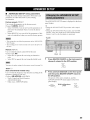
XM Satellite
millions
Radio is the satellite
of listeners
live daily. The XM Satellite
more than 150 digital
coast: 67 commercial-free
hop to opera, classical
channels
of premier
entertaimnent
of choice
music
sports,
States
channel
accessory
from coast to
featuring
bluegrass
talk, comedy,
progrannning;
Connect
lineup includes
channels,
to country,
of the traffic and weather
metropolitan
Radio
channels
with
broadcasting
radio service
across the United
hip
to blues;
children's
i_iii
the XM Connect-and-Play
(sokt separately)
this unit. (For details,
provided
Iil_ilIl!_li
digital
antenna
to the XM jack on the rear of
refer to the operating
with the XM Connect-and-Play
instructions
digital
antenna
accessory.)
64
XM jack
and
and more than 26 channels
information
for major
iiiiiiiiiiiiiiiiiiii
areas nationwide.
iiiiiiiiiiiiiiiiiiiiii+++
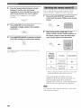
Because
XM Satellite
Radio
will need to set up an account
XM using your XM Satellite
your ID number,
and activate
information
visit the XM Satellite
service,
service
Radio I[) number.
follow "Activating
on page 29. For flmher
services,
is a subscription
XM Satellite
website
with
To check
on XM Satellite
Radio
you
Radio"
Radio
,ii;iil
ili; ;!iiiiiiiiiiiiiiE
at
"http://www.xmradio.com".
• The XM Satellite Radio service is only available in the 48
contiguous United States (not available in Alaska and Hz_waii).
• XM Connect-and-Play digital antenna uccessory and monthly
subscription are sold separately. For details, visit the XM
Satellite Radio website at "http://www.xmradio.com".
• For infornmtion
antenna
on obtaining
accessory,
"http://www.xmradio.com"
sells XM Ready
• To ensure
signals,
READY
Information
from
XM Satellite
Radio,
Inc.
Hardware and required basic monthly subscription sold
separately. Premimn Channel available at additional monthly
cost. Installation costs and other fees and taxes, including a onetime activation fee may apply. Subscription fee is consumer
only. All fees and programming sut'_ject to change.
Subscriptions subject to Customer A_eement available at
xn_adio.com. Only available in the 48 contiguous United
States.
© 2005 XM Satellite Radio Inc. All rights reserved. All other
trademarks are the property of their respective owners.
26
or consult
digital
Radio website
your
at
local retailer
that
products.
the optimal
reception
of the XM Satellite
the XM Connect-and-Play
must be placed
obstacles
olltdoors+
the XM Connect-and-Play
visit the XM Satellite
at or near a southerly
digital
antenna
lhcing
window
in the path to the sky. You can mount
Radio
accessory
with no
it indoors
or
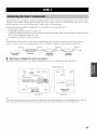
:li_J_Y__|l_llllil_l:y__yl][e,
llllhT[hT[J
@ INPUT selector
Selects XM as the input source.
This section
describes
for the XM Satellite
the functions
Radio
of each control
used
tuning.
The following controls on the front panel and the remote control
are only available when XM is selected as the input source and
the XM Connect-and-Play
to the aM
digital antenna accessory is connected
ack on the rear panel of this unit (see "XM Satellite
Radio connections").
•
@ CATEGORY
All Channel Search mode
Switches between channel categories while staying ill
the All Channel Search mode.
Category Search mode
Sv,.itches between channel categories.
Preset Search mode
Selects the preset channel group (A to E).
@ Preset channel number buttons
Select the preset channel nmnber (1 to 8) directly.
Pressing these buttons switches the search mode to the
Preset Search mode.
Controls on the front panel
@ MEMORY
Stores a radio channel ill the system memory.
@
SEARCH
Switches
Search,
MODE
between
tile All Channel
and Preset Search
modes
Search,
Category
(see page 31).
XM ANT (ANTENNA)
Sho'a.s tile reception
digital
3)
antenna
level of the XM Connect-and-Play
(sold separately).
TUNING/CH
<:3 / t:>
All Channel
Search
Searches
mode
for a radio channel
Press and hold for quick
Category
Searches
Search
within
all channels.
search.
mode
for a radio channel
w.ithin the selected
category. Press and hold for quick search.
Preset Search mode
Selects
tile preset channel
number
(1 to 8).
@ DISP (DISPLAY)
Switches
tile XM Satellite
front panel display
category
Radio information
between
and artist name/song
channel
sho'a,n ill the
number/name,
title (see page 30).
27
|_i_I___|I3||iI:I:y__yl][olIIIJ_TIhT[,
•
Controls
on the remote
controls
@ ENT. (ENT) (ENTER)
Confirms an entered channel number when thisunit is in
the Direct Number Access mode (see page 33).
@ SRCH (SEARCH) MODE
Switches between the All Channel Search, Category
Search, and Preset Search modes. (see page 31)
@ DISPLAY
Sw,itches XM information such as channel nnmber/name,
category, or artist name/song title displayed in the front
panel display and on-screen display. (see page 30).
@-
Zone 2 remote
only
-(6) {_}=
@
(9)=
<x;
control
(sold separately)
Input selector/numeric buttons
All Channel Search or Category Search mode
Use l to 9 and 0 to enter a channel number directly.
Also refer to @ NUMBER.
Preset Search mode
Remote
control
(supplied)
@ Numeric buttons
All Channel Search or Category Search mode
Use 1 to 9 and 0 to enter a channel number directly.
Preset Search mode
Use 1 to 8 to enter a preset channel number directly.
@ A-E/CAT. (CATEGORY) < / > (<s / _)
All Channel Search mode
Switches bet'a,een channel categories while staying in
the All Channel Search mode.
Category Search mode
Sw,itches betw,een channel categories.
Preset Search mode
Selects the preset channel group (A to E).
PRESET/CH _, / v (A / V)
All Channel Search mode
Searches for a radio channel within all channels. Press
and hold for quick search.
Category Search mode
Searches for a radio channel within the selected
category. Press and hokt for quick search.
Preset Search mode
Selects the preset channel number (1 to 8).
@ MEMORY
Stores a radio channel in the system memory.
@ XM
Selects XM as the input source.
28
Use 1 to 8 to enter a preset channel number directly.
Also refer to @ NUMBER.
Zone 2 remote
control
(sold separately)
You must press and hold @ NUMBER
these buttons to enter numbers.
before you press any of
@ ALL
Selects the All Channel Search mode.
@
NUMBER
Press and hold before you press the input selector/numeric
buttons to switch the function to enter numbers.
@ CAT. (CATEGORY)
Selects the Category Search mode.
@ PRESET
Selects the Preset Search mode.
@
CD/XM
Switches
remote
switch
the function
control
between
controlling
of the control
numbered
controlling
buttons
on the Zone 2
@, @, @, @, @ and @
YAMAHA
the XM Satellite
CD players
Radio
features.
and
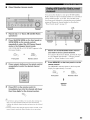
To sign up for an account
service,
Follow
an XM Satellite
the procedure
then visit the website
with the XM Satellite
Radio
ID number
Radio
is required.
below to check your ID number,
and
at "http://activate.xnlradio.com"
or
call "1-800-XM-RADIO
with your m_Lior credit
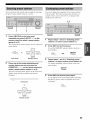
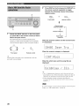
Press SEARCH MODE on the front panel (or
SRCH MODE on the remote control)
repeatedly to select the All Channel Search
mode.
(1-800-967-2346)"
ALL CH SEARCH appears in the front panel display.
to sign up
or
card handy.
2
3
Front panel
3
Remote
control
Press TUNING/CH <1 / c> on the front panel
(or PRESET/CH A / v on the remote control)
to select channel O.
or
Rotate the INPUT selector on the front panel
(or press XM on the remote control) to select
XM as the input source.
Front panel
Check the XM Satellite Radio ID number
shown in the front panel display and write it
down.
Front panel
If CHECK
display,
accessory
Remote control
ANTENNA
appears
in the front panel
the XM Connect-and-Play
may not be connected
the rear panel of this unit properly.
Radio connections"
connection.
ID:
digital
antenna
to the XM jack on
See "XM Satellite
on page 26 and check the
29
|_j_I___|I3||iI:I;y__yl][OIIII]_T/hT[,
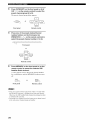
Press DISP on the front panel (or DISPLAY on
the remote control) repeatedly to toggle
between the following channel information
display modes.
Front panel
Remote
control
Channelname
Channel
Rotate the INPUT selector on the front panel
(or press XM on the remote control) to select
XM as the input source.
The XM information (channel number/nanle,
category or artist name/song title) for the currently
selected channel appears in the front panel display.
category
Channel number_
Artistname
Song title
When the channel number and the channel name
are displayed:
7
=NPIJT
O
Front panel
1'°¢°:; ,°1¢°:;'°1
L (::.1;'°)'(::.1.J
or
('°°m
..........
°'1°'°.....
LJ (:::m
(:::m).oo' :; :;'' ....:°°';
/
/
When the channel category is displayed:
Remote
control
Selecting XM as the input source autolnatically recalls the
previously selected channel.
<i(2A[ )F;)0c i<
When the artist name and the song title are
displayed:
1
• 1Jp to 14 alphanumeric characters can be shown in the lhont
panel display at once. If the information contains more than 14
characters, the information scrolls from the right to the lett.
• If the inlormation contains a character that cannot be
recognized by this unit. the character will be shown with an
underbar
"".
If a status message or all error message appears ill the front panel
display, see "XM Satellile Radio" on page 44.
30
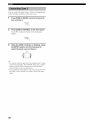
You can search for the desired channel by using one of the
three search modes (All Channel Search mode, Category
Search mode or Preset Search mode). You can also enter
the number directly to select the desired channel (For
details, see "Direct Number Access mode" on page 33).
•
Press CATEGORY on the front panel (or A-E1
CAT. < / > on the remote control) repeatedly to
switch between channel categories.
or
All Channel Search mode
PRE;ET/CH
2
4
Front panel
Remote
control
Press TUNING/CH <1 / _> on the front panel
(or PRESET/CH A / v on the remote control)
repeatedly to search for a channel within all
channels.
<J _U_E_G_CHc
or
1
2
Repeat step 1 in "Basic XM Satellite Radio
operations".
Press SEARCH MODE on the front panel (or
SRCH MODE on the remote control)
repeatedly to select the All Channel Search
mode.
Front panel
Remote
control
To quickly search lk_ra channel, press and hold
TUNING/CH <:3/ C>on the h'ont panel (or PRESET/CH A / v
on the remote control).
ALL CH SEARCH appears in the front panel display.
or
Front panel
_
Remote
control
31
•
Category
Search
•
mode
Preset
Search
mode
Prior to selecting a preset channel in tile Preset Search
mode, you must preset the XM Satellite Radio channels
(see page 33). All preset channels (AI to ES) recall "001
Preview" as the factory setting.
2
2
1
Repeat step 1 in "Basic XM Satellite Radio
operations".
2
Press SEARCH MODE on the front panel (or
SRCH MODE on the remote control)
repeatedly to select the Category Search
mode.
3
1
Repeat step 1 in "Basic XM Satellite Radio
operations".
2
CAT SEARCH appears in the front panel display.
Press SEARCH MODE on the front panel (or
SRCH MODE on the remote control)
repeatedly to select the Preset Search mode.
PRESET SEARCH appears in the front panel display.
or
Front panel
EOEr
Remote
or
control
Front panel
3
4
Press CATEGORY on the front panel (or A-E/
CAT. < / > on the remote control) repeatedly to
switch between channel categories.
or
3
Remote
control
Press CATEGORY on the front panel (or A-E/
CAT. < / > on the remote control) repeatedly to
select the preset channel group (A to E).
_JB/C_E
or
PREgET/CH
PRESET/CH
Front panel
Remote
control
Front panel
Press TUNING/CH <t / t:> on the front panel
(or PRESET/CH _, / v on the remote control)
repeatedly to search for a channel within the
selected channel category.
- JTUNmGICH
Remote
control
Press TUNING/CH <1 / _> on the front panel
(or PRESET/CH/,, / v on the remote control)
repeatedly to select the preset channel
number (1 to 8).
or
TU_ENG/CHC
or
pRESET/¢H_'-,S
PRESET/Cff",_,"
Front panel
Remote
control
To quickly search %r a channel, press and hold
TUNING/CH <1 / C>(or PRESET/CH/x / v on the remote
control).
32
Front panel
Remote
control
You can also select the preset channel number directly by
pressing the preset channel number buttons (1 to 8) on the lront
panel or the numeric buttons (I to 8) on the remote controh
_Ij_I.___|I:/I|iI:I;y__yl][oIIIIhT/hT[J
•
Direct Number Access mode
You can use this feature
Radio channels
preset channel
groups,
recall any preset
Search
mode"
channel
numbers
in each of the 5
AI to E8). You can then easily
channel
group and the preset
"Preset
to store up to 40 XM Satellite
(8 preset
by selecting
channel
the preset channel
number
as described
in
on page 32.
2,5
1
Repeat step 1 in "Basic XM Satellite Radio
operations".
2
Press SEARCH MODE on the front panel (or
SRCH MODE on the remote control)
repeatedly to select the All Channel Search
mode or the Category Search mode.
ALL CH SEARCH or CAT SEARCH appears in the
front panel display.
3
Search
for the XM Satellite
you want
or
Front panel
To search
Remote control
4
Radio
to set as a preset
for the desired
channel
channel.
channel,
pert_rm
in "All Channel Search mode", "Category
mode" or "Direct Number Access mode".
tile steps
Search
Press numeric buttons on the remote control
Press MEMORY on the front panel or on the
remote control.
sequentially to enter the desired channel
number.
The MEMORY indicator flashes in the front panel
display for approximately 5 seconds.
or
Front panel
Remote control
MEMORY
Flashes
Press ENT. on the remote control to
immediately tune into the channel with fewer
than three digits for the channel number.
• If no button is pressed within a ti:w seconds after entering onedigit or two-digit chmmel number, this unit automatically
confirnls the entered channel number and tunes into the selected
channel.
• Pressing a button other than the numeric buttons or ENT. on the
remote control cancels the Direct Number Access procedure.
33
|_j_I___II3||iI:I;y__yl][OIIII]_T/hT[,
Press CATEGORY on the front panel (or A-E/
CAT. < / > on the remote control) to select the
preset channel group (A to E).
The preset channel group letter appears.
A_B_C/D/E
or
PRESET/CH
Front panel
Remote
control
Press one of the preset station/channel
number buttons on the front panel (or
PRESET/CH A / v on the remote control) to
select the preset channel number (1 to 8).
Front panel
or
Remote
control
Press MEMORY on the front panel or on the
remote control to preset the selected XM
Satellite Radio channel.
A colon appears next to the preset channel number
for confirmation, and the MEMORY indicator turns
oft'.
MEMORY
or
Front panel
Remote
control
• Steps 3 to 5 mnst be done respectively within 5 seconds while
the MEMORY indicator is flashing in the _ont panel display.
Otherwise, the XM Satellite Radio channel presetting procednre
is automatically canceled.
• Presetting a new chmmel clears the former preset channel stored
in the same preset channel gonp
34
and mnnber.
•
ADVANCED SETUP menu parameters
Change the initial settings (indicated in bold under
parameter)
to reflect the needs of your listening
environment.
Factory
presets
The ADVANCED SETUP menu is displayed in the front
panel display.
i=q:;I:i!!!2!!;E]"
Use to reset all parameters
to the factory
Choices: CANCEL,
RESET
Select CANCEL
presets.
if you do not want the parameters
this unit to be initialized
presets.
Select RESET
each
when you reset the factory
if you want all of the parameters
unit to be initialized
of
when you reset the factory
of this
• During the AD\__N( ED SETUP procednre, audio outpnt is
mnted.
• During the AD\__N( ED SETUP procednre, only MASTER
O_OFF, A/B/C/DiE and the preset statio_ channel nnmber
buttons (1 and 2) on the front panel are operational.
presets.
1,2,5
• This setting does not affect the parameters
SETUP menu.
in the ADVANCED
• The resetting process starts next time yon turn on the power of
this unit.
Remote
i:;I:i!!!M
0[i!!!
Use to switch
Choices:
the remote
control
ID of this unit.
ID1, ID2
Select ID1 to operate
3
2,4
this unit using an alternative
code
Select ID2 to operate
this unit using the default
code.
Press
MASTER
release
ON/OFF
it outward
on the front
panel to
to the OFF position.
MAsr_R
You must also make settings for the remote control (see page 36).
Tuner ]i...i
(Asia and General models only)
Use to switch the frequency step selection according to the
frequency spacing in your area.
Choices: AM10/FMIO0, AM9iFM50
• North, Central and South America:
AM 10FM 100 (kHz)
Other areas: AMgiFM50 (kHz)
Press
and hold
and then
press
A/B/C/DIE
MASTER
on the front
ON/OFF
panel
inward
to
the ON position.
The power
of this unit is turned
ADVANCED
SETUP
on, and the
menu appears
in the fi'ont
panel display.
_°_°_
While holding down,
__
press
o,_
35
l_t',l_ h'N=,',I"I"iI
q"
Press the preset station/channel number
buttons (1 and 2) on the front panel
repeatedly to move through the menu and
select the parameter you want to adjust.
See page 3 5 for a complete list of available
parameters.
You can select the unit you want to operate
remote
1
control
by switching
the remote
with the
control
ID.
Press and hold CODE SET on the remote
control and then press TUNER on the remote
control.
CODESET
Press
AIB/C/DIE
repeatedly
on the front
to toggle
between
panel
the available
parameters.
Press
MASTER
to the OFF
ON/OFF
position
to release
to confirm
it outward
While holding down CODE SET on the
remote control, use the numeric buttons on
the remote control to enter the three-digit
code number listed in the table below.
your setting.
MA'_TE_
CODESET
The settings you made are reflected next time you turn on the
power of this unit.
Remote
control ID:'
Function
Code number
To operate this
unit using an
alternative code.
801
To operate this
unit using the
det;ault code.
802
(this unit's
setting)
ID l
ID2
(default setting)
* \_len you change the remote control ID, you must switch
the remote control ID of this unit (see page 35).
When using multiple
amplifiers
may unwantedly
simultaneously.
codes
YAMAHA
with the same default
operate
receivers
or
code setting,
you
those components
In this case, set one of the alternative
for this unit to operate
this unit separately.
Also change the remote control ID of the Zone 2 remote control
(sold separately) (see page 9).
36
This unit allows you to configure a multi-room audio and video system. The Zone 2 feature enables you to set this unit to
reproduce separate input sources in the main room and in Zone 2 (the second room) simultaneously. You can also control
this unit from the second room using the Zone 2 remote control (sold separately).
You need the following additional equipment to use the multi-room system of this unit:
• Zone 2 remote control
An infrared signal receiver t_r the second room
An infrared emitter for the main room. This emitter transmits the infrared signals sent by the Zone 2 remote control in
Zone 2 to the components in the main room.
An amplifier and speakers for the second room
_.,#._
Some YAMAHA models are able to comlect directly to the REMOTE OUTjack on the rear panel of this unit. If you own these
products you may not need to use an infrared emitter. Up to six YAMAHA components can be comlected as shown below.
REMOTE
Infrared signal
receiver
REMOTE
This unit
REMOTE
REMOTE
YAMAHA
component
YAMAHA
component
•
Multi-room
configuration
and connections
The following illustration shows an example of the multi-room system confim_ration and connections.
ZONE
2 AUDIO
OUT
Amplifier
DVD player
(or other componenp,)
AUD!O
This unil
IN
)/)
................J
lelllOle
[
conlro]
Infrared
receiver
signa
%2
Infrared
emitter
Main room
(Main Zone)
REMOTE OUT
Second
room
(Zone 2)
REMOTE IN
Since there are many possible ways to connect and use this trait in a multi-room configuration, we reconnnend that you consult with
yottr nearest authorized YAMAHA dealer or service center for the Zone 2 comlections that best meet }'our requirements.
37
P4ql'l_'
You call control the input source of Zone 2 independently
of the listening conditions in the main room.
1
Press ZONE 2 ON/OFF on the front panel to
turn on Zone 2.
2
Press ZONE 2 CONTROL on the front panel
The ZONE 2 indicator flashes in the front panel
display.
While
the ZONE
the INPUT
select
2 indicator
selector
is flashing,
on the front
the input source
of Zone
rotate
panel to
2.
INPUT
• You can also select the input soarce by using the Zone 2 remote
control (sold separately). Press POWER on the Zone 2 remote
control to turn on Zone 2, and then press one of the input
selector buttons to select the input sonrce.
• You can mute the sound output to Zone 2 by pressing MUTE on
the ZONE 2 remote control. Press again to restore the sound
output.
38
•
Controlling
this unit
The shaded areas below can be used to control this unit.
The buttons inside the
dotted lines control this
unit in any mode
(POWER• STANDBY•
•the input
selector buttons,
VOLUME +_ and
MUTE).
•
Controlling other components
The shaded areas below can be used to control other
audio and video components made by YAMAHA and
other manuf:tcturers. Each button has a different
function depending on the selected component. Select
the component you want to control by pressing one of
the input selector buttons. The name of the selected
component appears in the front panel display.
The input selector
buttons switch the
fimction of the
component
control
area below.
Component
control
area
Youcan controlup
to 6 different
componentsby
setting the
appropriateremote
controlcodes(see
page 41).
[
39
|:J.,_j_[O]I_[I,[O]_TII:{O]Ilffff__IlI]:I-'_"
In addition to controlling this unit, you can also control
other audio and video components made by YAMAHA
and other manufacturers using the supplied remote
control. To control other components, you must set the
appropriate remote control codes.
c? C) C) _
C) C9 C) C?
8):
>7,
®_lillllll
DVDplayer
_-__
VCR
_
'_
AV
POWIR
Po_x_q *l
Power
'_
TV
POWEI_:
TV powcl
TV
':1
pI)_cl
Digital TV/
Cable TV
TV
Pow*.']
,!l
VCp.
power
Po_cl
TV
v(p.
'_
_J_d
Seardlbl_kward
c>t>
Seardl
Setlh
h,rward
Sellh
ba_kvxlld
Ibl_
lid
semh
RIC/
I)ISC
,@
SKIP
ba_ k_
Skip
Io_
I)isc
skip
,;l
VCP.
ba
kwald
bl
V(I
>. searh
VCP.
I )lwald
Skip
povv_q
se trch
kwmd
setEh
Tape deck
Powel *1
TV powel
Scarh
Search
MD recorder
Tuner
Pm_er =:l
Pm_er ! 1
Powel ! i
TV power
TV power
"I'V po_ei
ba{k_ard
Search ba{kwmd
Sea_h ba kwa_d
H'Y MOI)E ,2
h,rward
Se_Eh
Search
H'Y
rid
P.ec
VCP.
_ec
VCP.
rec
Skip
ba_k_x
Skip
I)isc
rid
backwald
FRI
Q/I"I
I )_wald
I)ircclion
B
Skip
I_ ward
EON
*2
skip
Rec
Slop
VCp.
slop
VCP.
slop
Slop
Slop
Pause
Paise
VCp.
pause
VCP.
pause
Pause
I)eck
C>
pla 3
Pla}
VCP.
pla 3
VCP.
pla 3
Pla}
Pkl}
TV
VOI,
TV
CH
TV
CH
TV channel
Channel
Channel
'_
TV
MU'I'I
TV
TV
TV
'_
Trl'I,I
Tille
'@)
I NTEP.
Menu
_nlei
Menu
selecl
Menu
seled
TV
+
+
volume
TV channel
+
mule
TV
_o[tlme
TV
xoIume
Channel
+
+
T V "_OILIme +
_A}ltlme
TV
M)lume
_ohlm{
Channel
mule
Tille
+
+
mute
T V ".oltlme
+
"I'V _ohlnle
Pause
Hay
TV
\,o[ume
TV
_oklnle
+
TV
volume
TV
volume
+
volume
TV
volume
TV
channel
TV
channel
TV channel
Mule
TV
TV
TV
mule
1W
+
mule
TV channel
mule
+
+
TV
TV channel
TV channel
*2
Slop
A/B
TV channel
+
_2
XT
Rec
Channel
Channel
Tille
STAP.T
Skip
Sl/!p
VOI.
I_}lwmd
A
00
T V \olulrle
.d
I)ircclion
[]
+
h,l_
I_)iward
tld
TV
'_
CD player
TV channel
+
+
mul_
Band
"I'ille
Presel
up
(1 Io8)
PRESET/CH
A
Menu
up
Menu
up
Menu
up
PRESET/CH
v
Nlenu
down
Menu
down
Menu
down
Presel
down
(1 Io8)
A
1/CNI"
<
Menu
kll
Menu
lell
Menu
Presel
kll
(A
A
'_
'_1)
I/CAT
)
Menu
_ight
Menu
righl
I_:I TI_Ip.N
ReItlrn
F:et um
P.elu HI
TV
TV illptll
TV
TV
INPUT
I 9. 0, +I0
Numeric
Buttons
inpul
Numeric
bullons
Menu
Presel
tip
(A Io E)
_ight
P.elur n
inpul
Numeric
Inpul
bullons
TV
NulnelJc
Buttons
illptll
Numeric
TV illptll
butlons
'_P)
INT
'_)
MINU
Menu
Menu
Menu
'_
I)ISPI,AY
I)ispla3
I)ispla}
I)ispla
'1 This bulton
ffmciions
only when Ihe original
I nleUlec
remote conno]
'2 These bullons ltlnclion for Europe model only.
4O
dl
inpul
hldex
bul[oll
mimetic
oflhe
TV
Numeric
Enlei/
Inle_
down
I_> E)
3
component
I)ispla}
lifts tlae POWER
I)isplay
bullon.
1W
bullons
P_set
input
stations (I-8)
:]_[i_[oJfl_J[elo]_T#l:fo]ll___|l#]:l_;
Press and hold CODE SET on the remote
You can control
appropriate
other components
remote
control
codes.
each input source. For a complete
by setting
Codes
can be set up for
list of available
control codes, refer to "LIST OF REMOTE
(?ODES" at the end of this manual.
The following
(Library)
table show the default
and the remote
control
the
remote
control and then press one of the input
selector buttons on the remote control to
select the input source you want to set up.
CONTROL
component
gODESET
category
code for each input
source.
Remote control code default settings
You must press and hold CODE SET throughout this operation.
Default
Input
source
component
category
(Library)
Manufacturer
Default
YAMAHA
code
CD
CD
YAMAHA
199
M D/TAP E
TAPE
YAMAHA
499
DVD
DVD
YAMAHA
699
DTWCBL*
VCR
PHONO
While holding down CODE SET on the
remote control, use the numeric buttons on
the remote control to enter the three-digit
remote control code for the selected input
source.
When the setting succeeds, "PRESET OK" appears;
however, when it does not, "PRESET NG" appears in
the front panel display.
To reset the code, enter the default code for each
input source listed in the remote control code default
settings table.
* You can only set the TV remote control codes *br the DTVi
CBL button. However, other remote control codes can be set
for an?"mpnt selector buttons except DTViCBL.
_ODE_ET
Not
You may not be able to operateyonr other YAMAHA
components evan if the YAMAHA remote control code is
initially set as listed above. In this case. try setting other
YAMAHA remote control codes.
• If the mannihcturer of your component has more than one code.
try setting each of them until you find the correct one.
• You can only assign one remote control code to each inpnt
selector button.
41
Refer to the chart below
if this unit does not function
properly.
if the instructions below do not help, set this unit to the standby
authorized YAMAHA
dealer or service center.
•
If the problem
you are experiencing
mode, disconnect
the power
is not listed below or
cord, and contact
the nearest
General
See
Problem
Cause
Remedy
page
This
on.
unit
fails
to turn
Tile power supply cozd is not connected
the plug is not completely inserted
The impedance
02
setting is inconect.
No sound
SELECTOR
switch on
on
11
Check that the speaker wires are not touching each
other and then alrn the power of this unit back on
Set the IMPEDANCE
SELECTOR
switch
to either
Set this trait to the standby mode, disconnect the
power supply cord, plug it back in after 30 seconds,
or strong
then use it nonnally.
static electzici_,),
Inconect input or output cable
connections
Connect the cables properly
the cables may be defective
No aplJropriate
Select an appropriate
input source has been
_ZL'Bswitches
are not set
are not secme.
If tile problem
persists,
15
Turn on the conesponding
SPEAKERS B.
15
Check that the IMPEDANCE
conect.
SPEAKERS
A or
11
SELECTOR
setting is
11
10
cable connections
Connect the cables properly.
the cables may be defective
Inconect
cotmol,
setting fo_ the BALANCE
Set the BALANCE
position.
control
If the problem
pmsists,
to tile app!opriate
The + and
wires are connected in
reverse at the amplifier or tile speakms
Connect
phase
the speaker
A "humming"
can be heard,
Inconect
Connect
pmsists,
tile audio plugs firmly. If the problem
the cables may be defective
No connection
GND terminal,
The volume
level
low while playing
record.
The volume
is
a
level
cannot be increased,
or the sound is
distorted.
42
from the turntable
to the
Make the GND connection
this unit
between
on a turntable
The turntable should be connected
the MC head amplifier.
Tile component
to tile MDi
Turn on tile powel
connected
off.
16
wires to the correct + and
The record is being played
with an MC camidge
TAPE OUT jacks of this unit is ammd
11
Check that the speaker wires are not touching each
other and then alrn the power of this unit back on
Inconect
cable connections
10
input somce with the INPUT
There is a lack of bass
and no ambience,
sound
11
selector on the fiont panel (or one of the input
selector buttons on the remote control)
Secllre tile connections.
The protection circuitz T ha s been activated
because ofa shozt circuit, etc.
11
of this unit is turned otl_
This unit has been exposed to a strong
external electric shock (such as lightning
Speaker connections
Only the speaker
one side can be
heard.
to match yore speakers.
end when the powa
The SPEAKERS
properly.
suddenly
supply cozd fimfl_
the rear panel is not set to either end
selected,
The sound
goes off.
tile powm
Set the impedance
The protection circuitzy ha s been activated
because of a shozl" circuit, etc.
The IMPEDANCE
Connect
the turntable
11
10
and
to this unit through
of the conll3onent
10
The sound
is
degraded when
listening with the
headphones
connected
to the CD
The power of this trait is turned off. or this
unit is set to tile standby mode.
Tmn on the power of this unit.
14
player or the tape
deck connected
to
this unit.
The sound
low.
level is
The LOUDNESS
Using the BASS,
TREBLE,
BALANCE
control
The PURE DIRECT
is fimctioning.
button
is turned
on
Set the LOUDNESS
control
to tile FLAT position.
The PURE DIRECT
those controls.
button must be tin-ned off to use
and LOUDNESS
controls does not
affect the tonal
16
16
quality.
•
Tuner
See
Problem
Cause
FM stereo
reception
noisy.
There
The particular
is
is
characteristics
Remedy
Check the antenna
of the FNI
FM
with a good
antenna.
T_y using a high-quality
There
Adjust the antenna
interfez ence.
is multipath
interference.
AM
The signal is too weak
FM antenna
method
to eliminate
the multipath
T_y using a high-quality
directional
aming
FM antenna
12
method
21
method.
This unit has been discotmected
The desired
station cannot
be tuned in
with the
automatic
The signal is weak or the antenna
connections
are loose.
tbr a long
Preset the stations again
period.
22
Tighten the AM loop antenna
it tbr the best reception.
T_y using the manual
connections
and orient
tuning method
21
method.
There are
continuous
crackling and
hissing noises.
There are
buzzing
whining
aming
position
T_y using the maimal
Previously
preset stations
can no longer
be tuned in.
tuning
T_y using the manual
12
directional
FM
The desired
station cannot
be tuned in
with the
automatic
tuning
connections.
steleo broadcasts being received may
cause this problem when the t_ansmitter is
too far away or the anteima input is poor.
distortion,
and
clear reception
cannot be
obtained even
page
The noises may result fiom lightning,
fluorescent lamps, motors, thamostats
other electrical equipment,
A TV set is being used nearby
or
T_y using an outdoor antenna and a grolmd wire
This will help somewhat, but it is difficult to
eliminate all noise
Move this unit away from the TV set.
and
noises.
43
•
XM Satellite Radio
Cause
Error message
i==i...ii:::'i==i..'
,...=i H....,...=F..
i {_::,r'.,l%T
,..q L.'r'_ i
1%..'
'...ll
¢"1H "r' i:::' i..i i.. h"i
r'_H i L..HHr"I
'i' i..h';3
.LH'..a
...l .l. _...ll _r'_l
I
r"l .l. l".
._"_..=M %
...............
..............
...'
Remedy
Tile XM Connect-and-Play digital antenna
accessory is not connected, or does not work
properly.
Check the XM Connect-and-Play digilal anlcnna accessory
conneclk)ns.
The XM user encryption code is being updated.
Wait until the encryption code is updated.
The signal is too weak.
Check the XM Connect-and-Play digital antenna accessory
connections and orient it for the best reception.
It lakes longer Ihan four seconds for audio or
lexl data Iobc decoded.
Wait until the decoding process has finished.
The XM Satellite Radio channel you selected is
not currently broadcasting any signal.
Check the channel number again or selecl another
Satellilc Radio channel.
The channel station ID (SID) is no longer
available.
...............
No artisl name/fealure
available.
No channels
or song/program
are available
title is
for Ihe selected
calegory.
•
XM
Select anolher channel category by pressing CATEGORY on
the fronl panel (or A-E/CAT. < / > on Ihe remote control)
repealedly.
Remote control
See
Problem
The remote control
does not work nor
function properly,
44
Cause
W_ong distance m angle
Remedy
The _emote control will function within a maximtm]
range of 6 m (197 :_) and no more than 30 degrees
off-axis flora the fiont panel.
Direct sunlight or ligD'ing (flora an
inverter type of fluorescent lamp, ere ) is
striking the remote com_ol sensor of this
unit.
Reposition this unit.
The batteries are weak.
Replace all battmies.
The remote control ID and this unit's ID
do not n]atch
Switch the remote control ID or this unit's ID.
The remote com!ol code was not correctly
set.
T*y setting another code of the same manufactmer
using "LIST OF REMOTE CONTROL CODES" at
the end of this manual.
Even if the remote connol code is
correctly set, there are some models that
do not respond to the remote control.
Use the supplied remote control tbr the components.
page
9
9
35.36
41
AUDIO SECTION
VIDEO SECTION
Mininmnl
RMS Output Power
(8 £_
20 Hz to 20 kHz, 004%
• Video Siglml Type
THD) ......................
Dynamic Power (IHF)
18/6'4/2 £_) .....................................................
75 W + 75 W
105/125/150/178
W
Maximmn Output Power [Emope model only]
(t kHz, 07% THD, 4 £_) ....................................................
105 W
IEC Output Power [Europe model only[
(1 kHz, 004% THD, 8 £)_) ....................................................
84 W
Power Band Width
(008%
THD, 35 W. 8 £)_) ....................................
10 Hz to 50 kHz
Damping Factor (SPEAKERS
A)
20 Hz to 20 kHz, 8 £_ .................................................
150 or more
Maximmn Output Power (EIAJ)
[Asia and Genaal models only[
(1 kHz, 10% THD, 8 £)) ......................................................
• Maximmn
PHONO
CD, etc
• Frequency
CD, etc
CD, etc
..............................
................................
70 mV or more
2.2 V or more
Response
(20 Hz to 20 kHz) ...........................................
0 ± 05 dB
PURE DIRECT ON (t0 Hz to 100 kHz) ......... 0 ± 1 0 dB
• RIAA Equalization Deviation
PHONO ............................................................................
• Total Harmonic
PHONO
(20 Hz
CD, etc.
(20 Hz
± 05 dB
Distortion
to OUT (REC)
to 20 kHz, 3 V) ...........................................
to SPEAKERS
to 20 kilT, 35 W. 8 £_) .................................
0.02°;
E_ror (0 to
60 dB)
or less
82 dB or more
.........................
108 dB or more
................................
CD, etc ..................................................................
• Usable Sensitivity
76 dB/711 dB
0.2c/_/0.3%
• Stereo Separation
• Frequency
100 pV
2 dB or less
2.5 mV'47
k£)_
185 mVi47
k£_
0.47 V/390
(20 Hz) ...........................................................
• Tmfing Range
[U.S.A. and Canada models] ..............................
530 to 1711t kHz
[Asia and General models] .................
53(!/531 to 1710/161 I kHz
[Other models] ...................................................
531 to 1611 kHz
• Usable Sensitivity
300 !,V/m
• Power Consumption
..............................................................
Power Consmnption
.................................................
• Maximum Power Consumption
[Genelal model only[
(8 £), 1 kHz, 10% THD) ....................................................
[Austlalia model] ...............................
[General model] ...................................
[Olher models]
...................................
180 W
0.1 W
400 W
1 (Total 100 W maximmn)
2 (Total 50 W maximmn)
2 (Total 100 W maximum)
(W x H x D) ................................
(17-1/8"
435 x 151 x 308 1ran
x 5-15/16" x 12-1/8")
.............................................................
8.7 kg 119 lbs. 3 oz.)
are subject
to change
without
notice
±10 dB
±10 dB
35 kHz
(1 kHz)
.............................................................
• Power Supply
[U.S.A. and Canada models] ..............................
AC 120 \; 60 Hz
[Asia model] ....................................
AC 220/230-240
\\ 50/60 Hz
[General model] ................
AC 110/120/220/230-240
\; 50/60 Hz
[Austlalia model] ...............................................
AC 240 E 50 Hz
[Europe model[ ...................................................
AC 230 V, 50 Hz
* Specifications
BoosliCut (20 kHz) .........................................................
Tmnover Frequency .......................................................
Loudness
dB
65/50 dB or more
Characteristics
350 Hz
Attemmtion
45 dB
20 Hz to 15 kHz, +0.5_2
£_
........................................................
• Continuous
.......................................................
...........................
AM SECTION
• Weight
Frequency
( 1 kHz)
Response
• Dimensions
Turnover
TREBLE
1.0 [_V (I 1.2 dBf)
• Harmonic Distortion (1 kHz)
Mono/Stereo
................................................................
• Hea@hone
Output,Impedance
(Input 1 kHz, 185 mV 8 £_, 0.015% THD)
CD, etc .....................................................................
BoosliCut
(IHF) ........................................
• Signal to Noise Ratio (IHF)
Mono/Stereo
..............................................................
• AC Outlets
1/10 kHz) ........
3 dB
• Tmfing Range
[U.S.A. and Canada models] ...........................
87.5 to 107.9 MHz
[Asia and General models] ........ 87.5/87.50 to 11t7.9/1118.00 MHz
[Other models] ............................................
87.511 to 108.110 MHz
• Outpul Level/Output
hnpedance
OUT (REC) ................................................
185 mVil 2 kQ or less
SUB WOOFER OUTPUT ............................................
4 Vi1.2 k£_
ZONE 2 OUTPUT ...............................................
185 mVi1.2 k£_
• Tone Control
BASS
5 Hz to I1) MHz,
FM SECTION
• Standby
• Input Sensitivity/Input
hnpedance
PHONO ..................................................................
• Channel Separation
CD, etc (5.1 k£_ input sho_ed,
50 dB or more
GENERAL
• Resi&lal Noise (IHF-A NetwoN)
PURE DIRECT ON ..........................................................
• Gain Tracking
................................................
• Frequency Response (MONITOR OUT)
Composite .................................................
0.02% or less
• Signal to Noise Ratio (IHF-A Network)
PHONO (5 mV input sholted) ...............................
CD, etc. (185 mV input sho_ecl)
• Signal to Noise Ratio
NTSC
PAL
115 W
Input Signal
(1 kHz, 0.04% THD)
(1 kHz, 0.04% THD)
[U.S.A., Canada and Genaal models] ................................
[Other models] .......................................................................
Control
...........................................................
30 dB
45
LIST OF REMOTE
CONTROL
Pioneer
CODES
226,235,
392,
393,
394,
Tilshiro
396
255,268
328,
333,
349,
Tatung
392,
394
Portland
297,256
396,
363
Tcac
392,
394,
Proscan
293
JVC
392,
394,
344,
Tcchnics
325,328
345,346,
396
347
Tcknika
396
Kcndo
Tcleflmken
376,
396
Thom+_s
397
Thorn
393,396
Toshiba
335,389
Tomvison
363,396
Unitech
363
Universum
396,
Videosonic
363
W.WHouse
396
Wards
395,396,
336
Yamaha
399,
393,394
Zenith
344,368,
TV
254,
JC Penny
Admiral
292,293
Aiwa
294,276,
Akai
295,296
Prolon
297
Alba
AOC
296
297
Quasar
Radio Shack
234,235
299,293,
297
Kcnwood
392,
394,
Bell&Howell
292
RCA
293,297,
234,
Loewe
396,
337
Beslar
298
256,257,
258
Luxor
395
Blaupunkl
229,222
SABA
223,269,
265,266
LXI
393,
396,
Blue
298
Sampo
297
336,
349
Brandl
Brocsonic
223
297
Samsung
297,239,
262,275
248,
Magnavox
325,326,
Bush
296
Sanyo
295,233,
279,
Maranlz
Marta
392,
396
Clatronic
298
272,273,
274,
Matsui
396
Craig
Croslex
224
225
Sclmeider
Scott
296
297
Memorcx
328,
336,
Minolta
333,
349
297,226
Sharp
292,239,
Milsubishi
399,
344,348,
sky
Curtis
Malllis
Dacwoo
297,298,
283,
284
213,
232,
394
396, 397
396,
327,
392,
397
359,
353
Siemens
229
MTC
363,
397
Daytron
239
Signamrc
292
Muhitech
397,
348,
354
DVD player
Dual
298
Sony
263,
NEC
392,
394,
344, 383
DENON
623,624
Dwin
293
Sylvania
297,225
Nokia
393,
395
Funai
625
Emerson
297,224,
Tcleflmken
269,264,
395
HlTACHl
626
Fcrguson
223,265,266
Thomson
223,266
Okano
323
JVC
627
Firsl
298
Toshiba
292,226,
628
277,278
Videch
297,242
325,328
327
KENWOOD
Funai
Olympic
Orion
Mitsubishi
629
Fisher
295,233
Wards
297,239,
232
Panasonic
325,328.
355.
Fraba
298
Yamaha
299,292,
253,
378,
384,
385_ 386
Onkyo
Panasonic
632,633,634
623,635
GE
293,297,
Pentax
333,
349
Philips
699,647
Philco
325,328,
397
Philips
325,326,
328,
Pioneer
RCA
636,637,638
639
337,
357
239,232
216
328
377
227,228
line
224_
212
397,
214
265,266
267,
215
234,
237
VCR
297,298,
239,
Goodmans
296,298,
223
Admiral
395
Grundig
229,238,
249
Aiwa
396,
397,
398,
Hilachi
297,239,
242,
Akai
322,
323,
Audio Dynamic
Bell&Howell
392,
lCE
243,285
296
lrradio
ltl!Nokia
296
244,245
JC Penny
293,
JVC
296,246,
Kcndo
298
KTV
Oceanic
242
235,236
LG/Goldstar
Nokia
Samsung
642
Phonola
337
Sharp
643
324
Pilot
396
Sony
644
394
Pioneer
325
Toshiba
393
Quasar
325,328
LG/GOLD
Blaupunkl
Brocsonic
325,326
327
RCA/PROSCAN
Bush
322
Canon
325,328
CGM
396,
297,239
Citizen
396
Loewe
298,248
Craig
396,
363
LXI
293,297,
297,
234,
237
247,286
329
Realistic
332
Samsung
356,
THOMSON
646
328,
333,
335,
Yamaha
699,622,623
349,
358,
363, 397
393,
397,
328,
336,
359,
396, 363
CD player
354,
358,
363_
Yanmha
364,
366
397,
328,
333
Sansui
394
Daewoo
328,
334,
335
367
297,225,239
DBX
392,
394
393,
337
336,
Magnavox
Sanyo
Schneider
Maranlz
298
Dimensia
333
Scott
399,
335,
336,
Malsui
295
Dynatech
397
348,
359_ 354, 358
Memorex
297
Emcrson
327,
334,
Mitsubishi
299,297,
259,287
Fisher
393,
336
NEC
297,252,
282
Funai
397
244,245
GE
328,
245
Go Video
353
Nordmende
265,266
LG/Goldstar
396,
388
Onwa
296
Goodmans
334,
337
Panasonic
234,235,236,
Glundig
332,
338
Hitachi
325,333,
Nokia
N0kia
Oceanic
253,288,
Philco
297,225,239
Philips
225,298
211
Curtis
Mathis
342,
lnslant
Replay
ltt/Nokia
333,
343
325,328
393
396,
387
349,
397
645
325,326,
226,233
225_
634
STAR
199
CD recorder
Yamaha
499
Seleco
322
MD recorder
Sharp
395,382
Yanmha
Siemens
393
Signamrc
2000
395,397
Sony
368,
373,
379,
374,
372,
375
Sylvania
397,
325,
326, 328
Symphonic
397
Timdbelg
334
Tandy
397
599
Tape deck
Yamaha
799
397
376
379,
This product mainly uses lead-free solder.
© 2005 Y:AMAHACORPOP,
ATION All rights reserved,
YAMAHA
YAMAHA
YAMAHA
YAMAHA
ELECTRONICS
CORPORATION,
USA 6660 ORANGETHORPE
AVE., BUENA PARK, CALIF. 90620, U.S.A.
CANADA MUSIC LTD. 135 MILNER AVE., SCARBOROUGH,
ONTARIO M1S 3R1, CANADA
ELECTRONIK
EUROPA G.m.b.H. SIEMENSSTR.
22-34, 25462 RELLINGEN BEi HAMBURG, GERMANY
ELECTRONIQUE
FRANCE S.A. RUE AMBROISE CROIBAT BP70 CROISSY-BEAUBOURG
77312 MARNE-LA-VALLEE
YAMAHA
YAMAHA
ELECTRONICS
SCANDINAVIA
YAMAHA
MUSIC
GEDEK02,
(UK) LTD. YAMAHA HOUSE, 200 RIGKMANSWORTH
ROAD WATFORD, HERTS WD18 7GQ, ENGLAND
A,B. J A WETTERGRENS
GATA 1, BOX 30053, 400 43 V,_STRA FROLUNDA, SWEDEN
AUSTRALIA
PTY, LTD. 17-33 MARKET
ST., SOUTH
MELBOURNE,
3205 VIC., AUSTRALIA
FRANCE
YAMAHA CORPORATION
Printed in Malaysia c
WG05020
RX-497/RX-397
Read the following instructions instead of "IMPORTANT
on page i) on the OWNER'S MANUAL.
1
Read Iustructions
All the safety and operating instructions
shuuld be read before the product is operated.
2
Retain Instructions
The safety and operating instructions
should be retained for l_lture reference.
3
Heed Warnings
All warnings on the product and in the
operating instructions shoukl be adhered to.
4
Follow Instructions
should be fullowed.
5
Cleaniug
Unplug this product l)'om the wall outlet belore
cleaning. Do not use liquid cleaners ur aerusol cleaners.
6
Attachments
Do nut use attachments not recommended
the product mauulacturer as they may cause hazards.
7
14
All operating and use instructions
by
Water and Moisture Do not use this product near water for
example, near a bath tub. wash bowl. kitchen sink. or laundry
tub: in a wet basement: or near a swimming pool: and the like.
Accessories
Du not place this product on an unstable cart.
stand, tripod, bracket, or table. The product may fall.
causing serious i_iury to a child or adult, and serious
damage to the product. Use only with a cart. stand, tripod,
bracket, or table recommended by the manufacturer, or sold
with the pruduct. Any mounfing of the product should
lolh)w the manufacturer's instructions, and should use a
mountiug accessory recommended
manulhcmrelt
11
12
Ventilation
Slots and openings in the cabinet are
provided fur ventilation and tu ensure reliable operation of
the product and tu prutect it from overheating, and these
openings must not be blocked or covered. The openings
should never be blocked by placing the product on a bed.
sofa. rug, or other similar surface. This product should not
be placed in a built-in installation such as a bookcase or rack
unless proper ventilation is provided or the mauulhcmrer's
instructions have been adhered to.
Power Sources
This product should be operated only l?om
the type of power source indicated on the marking label. If
you are nut sure of the type of power supply to your home.
consult your product dealer or local power company. For
products intended to uperate lrom battery power, or other
sources, refer to the operating instructions.
Grounding or Polarization
This product may be equipped
with a polarized altemafing current line plug (a plug having
one blade wider than the other). This plug will lit into the
power outlet only one way. This is a safety feature. If you
are unable to insert the phlg fully intu the uutlet, try
reversing the plug. If the plug should still lhil to fit. contact
your electrician tu replace your obsolete outlet. Du not
defeat the sali:ty purpose of the polarized plug.
(1 to 14
Power-Cord Protection
Power-supply cords should be
routed so that they are not likely tu be walked on or pinched
by items placed upon or against them, paying particular
attention to cords at plugs, convenience receptacles, and the
point where they exit l?om the product.
Lightning
For added protection lot this product during a
lightuing storm, or when it is lell unattended and unused for
long periods uf time. unplug it lmm the wall outlet and
discummct the auteuna or cable system. This will prevent
damage tu the product due tu lightning and power-line
surges.
15
Power Lines
An outside antemm system should not be
h)cated in the vicinity uf overhead power lines or other
electric light or power circuits, or where it can fall into such
puwer lines ur circuits. When installing an uutside antemm
system, extreme care should be taken to keep l?om touching
such power lines or circuits as contact with them might be
fatal
16
Overloading
Do nut overload wall outlets, extension
cords, or integral convenience receptacles as this can result
in a risk of fire or electric shuck.
17
Ohject and Liquid Entry Never push ol_]ects of any kind
into this product through openings as they may touch
dangerous voltage points ur short-out parts that cuuld result
in a fire or electric shock. Never spill liquid of any kind on
the product.
18
Servicing
Du not attempt to service this product yourself
as opening or removiug covers may expose you tu
dangerous voltage or uther hazards. Reler all servicing to
qualified service personneh
19
Damage Requiring Service
Unphlg this product from the
wall outlet and reli:r servicing to qualified service personnel
under the following condifions:
by the
A product and cart combination should be
moved with care. Quick stops, excessive
force, and uneven surfaces may cause the
product an0 cart combiliation to uvertum.
10
13
SAFETY INSTRUCTIONS"
a)
b)
When the power-supply cord or plug is damaged,
If liquid has been spilled, or ohjects have fallen into the
product.
c)
d)
If the product has been exposed tu rain or water.
If the product does not operate normally by lollowing
the operating instructions. Acliust only those controls
that are covered by the operating instructions as an
improper a{ljustmeut of other controls may result in
damage and will often require extensive work by a
qualified technician to restore the product to its normal
operation,
If the pruduct has been dropped or damaged in any
way, and
When the product exhibits a distinct change in performance - this indicates a need lot service.
e)
l)
20 Replacement
PartsWhen
replacement
parts
are
required.
besure
theservice
technician
has
used
replacement
parts
specified
bythemanulhcturer
orh:ne
thesame
characteristics
astheoriginal
part.
Unauthorized
substitutions
may
result
infire.electric
shock,
orother
hazards.
21 Sali:ty
Check
Upon
completion
ofany
service
orrepairs
to
thisproduct,
asktheservice
technician
toperform
safety
checks
todetermine
that
theproduct
isinproper
operafing
condition.
22 Wall
orCeiling
Mounting
Theunitshould
bemounted
toa
wallorceiling
onlyasrecommended
bythemanufacturer.
23 HeatTheproduct
should
besituated
away
from
heat
sources
such
asradiators,
heat
registers,
stoves,
orother
products
(including
amplifiers)
that
produce
heat.
24 Outdoor
Antenna
Grounding
Ifanoutside
antenna
or
cable
system
isconnected
totheproduct,
besure
theantenna
orcable
system
isgrounded
soastoprovide
some
protection
against
voltage
surges
and
built-up
static
charges.
Article
810
oftheNational
Electrical
Code.
ANSI/NFPA
70.
provides
information
withregard
toproper
grounding
ofthe
mast
and
supporting
structure,
grounding
oftheleadqn
wire
toanantenna
discharge
unit.size
ofgrounding
conductors.
location
ofantenna
discharge
unit.
connection
togrounding
electrodes,
and
requirements
lk)rthegrounding
electrode.
EXAMPLE
OF ANTENNA
GROUNDING
j
NEC
POWER SERVICE GROUNDING
ELECTRODE SYSTEM
(NEC ART 250 PART H)
NATIONAL ELECTRICAL(ODE
YAMAHA CORPORATION
Printed in Malaysia _c_ WG63450