1
Italiano
Español
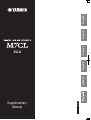
Supplementary
Manual
Français
V2.0
EN
DE
ES
FR
IT
RU
Deutsch
English
m7cl_v2_en.fm Page 2 Thursday, June 25, 2009 5:16 PM
This supplementary manual explains mainly the functionality that was changed
or added in version 2.0 of the M7CL firmware. Please read this in conjunction
with the M7CL V1.1 supplementary manual and the M7CL Owner’s manual.
You can download the most recent version of the Help file from the Yamaha
website.
http://www.yamahaproaudio.com/
■ Scene memory
Main changes
• You can now use the Global Paste function to easily
modify parameters across multiple scenes (p. 6).
■ Input channel operations
• Recall Safe for the attenuator can now be selected independently of EQ (p. 7).
• Now the top panel faders can also be used to adjust the
send levels from input channels to MATRIX buses
(p. 3).
■ Monitor/Cue
• In SENDS ON FADER mode, the send-destination
MATRIX bus can now be selected by pressing the
[MATRIX] navigation key and then pressing a [SEL]
key in the Centralogic section (p. 3).
• A monitor fader has been added to the monitor output
level control, allowing you to use the STEREO MASTER fader / MONO MASTER fader to control the level
(p. 5).
• The various channel parameters can now be saved
together in internal memory as channel library data
(p. 3).
■ User settings
• M7CL V2 Editor now allows you to make the same
user-defined key settings as on the console itself (p. 7).
■ Output channel operations
• The various channel parameters can now be saved
together in internal memory as channel library data
(p. 3).
• Additional functions are now available for assignment
to the user-defined keys (p. 7).
• Regarding compatibility of data you create (p. 7).
■ Input/output patching
• You can now select POST ON (immediately after the
fader and [ON] key) as the insert or direct output position (p. 4).
• When specifying or clearing a GEQ insertion, insert
will now be turned on/off automatically (p. 4).
■ EQ and Dynamics
• The minimum level for an input channel’s GATE
threshold level is now -72 dB (p. 4).
■ Grouping and linking
• When you enable channel link, HA gain and fader operations will now be linked while maintaining the level
difference between channels (p. 5).
2
m7cl_v2_en.fm Page 3 Thursday, June 25, 2009 5:16 PM
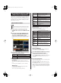
Input/output channel library support
Using the faders to adjust the
send levels to the MATRIX buses
(MATRIX ON FADER mode)
Until now, EQ and dynamics were managed as individual
libraries, but now the channel parameters (including HA
settings) can be managed together in units of channels as
channel library data, and stored, recalled, or cleared from
internal memory.
You can recall 200 different settings each from the input
channel library and the output channel library. For both
input and output libraries, only 000 (Initial Data) is a readonly preset.
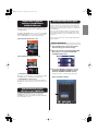
You can now use the top panel faders to adjust the send
levels from input channels not only to MIX buses but also
to MATRIX buses.
In SENDS ON FADER mode, you can now use the MIX/
MTRX ON FADER button to switch between the MIX
buses and MATRIX buses as the send destinations.
The basic operations are the same for input channels and
output channels.
[When MIX ON FADER mode is ON]
Using the channel library
1 Use the [SEL] keys to select the channel
1
whose settings you want to manage.
2
2 Press an encoder of the SELECTED CHANNEL section to access the SELECTED
CHANNEL VIEW screen.
[When MATRIX ON FADER mode is ON]
1
2
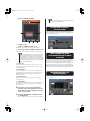
3 Press the LIBRARY tool button to access
the INPUT CHANNEL LIBRARY window /
OUTPUT CHANNEL LIBRARY window.
The library window contains the following items.
1 MIX/MTRX ON FADER select button
Each time you press this button, you’ll switch between MIX
ON FADER mode and MATRIX ON FADER mode.
[INPUT CHANNEL LIBRARY]
B MIX/MATRIX bus select button
Use these buttons to switch the send destination MIX bus or
MATRIX bus. The buttons will be joined if two buses are set
to stereo.
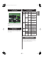
Using the Centralogic section’s
[SEL] keys to select a MATRIX bus
3
In SENDS ON FADER mode, the send-destination
MATRIX bus can now be selected by pressing the
[MATRIX] navigation key and then pressing a [SEL] key
in the Centralogic section.
4
3
5
6
m7cl_v2_en.fm Page 4 Thursday, June 25, 2009 5:16 PM
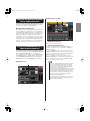
[OUTPUT CHANNEL LIBRARY]
NOTE
• If you recall to a channel that is channel-linked, linking will be
cancelled for the recalled channel.
1
POST ON added as an insert /
direct out position
You can now select POST ON (immediately after the
fader and [ON] key) as the insert or direct output position
for input/output channels.
2
3
4
5
6
1 CURRENT TYPE
(OUTPUT CHANNEL LIBRARY only)
Displays the type of channel selected by the [SEL] key.
B Library type (OUTPUT CHANNEL LIBRARY only)
Displays the type of channel for the library item in the list.
NOTE
Insert is automatically turned
on/off when GEQ insertion is enabled
or cancelled
• For the output channel library, if the type of channel selected
by the [SEL] key differs from the type of channel selected in
the list, an indication of “CONFLICT” is shown at the right of
CURRENT TYPE. Recall can be executed even if the “CONFLICT” indication is shown, but since the constituent parameters will be different, parameters that do not exist in the library
will be set to their default values.
If a rack in which a GEQ is mounted is specified as the
insert-out or insert-in, the other patch point will automatically be assigned to the same rack. At the same time,
insertion is now automatically turned on. Additionally, if
you defeat the insert-out or insert-in of a rack in which a
GEQ is mounted, the other patch point will automatically
be defeated, and insertion will automatically be turned off.
C Library list
Selects the library item that will be the object of the operation. The selected library item will move to the center, and
will be highlighted.
D STORE button
Stores the settings of the currently selected channel into the
selected location of the list. When you press this button, the
LIBRARY STORE window will appear, allowing you to
name the settings.
Changed minimum value of the
GATE threshold level
The minimum threshold level for an input channel GATE
is now -72 dB.
E RECALL button
Recalls the settings shown in the list into the currently
selected channel.
F CLEAR button
Clears (deletes) the library item selected in the list. When you
press this button, a dialog box will ask you to confirm the
Clear operation.
4 By turning any one of the multifunction
encoders, move the highlighted line in the
list to select the library number you want to
store, recall, or clear.
5 Press the STORE button, RECALL button,
or CLEAR button.
The rest of the steps are the same as for other libraries.
4
m7cl_v2_en.fm Page 5 Thursday, June 25, 2009 5:16 PM
[MONITOR popup window]
Channel link level differences maintained,
and can temporarily defeated
1
2
When you enable channel link, HA gain and fader operations will now be linked while maintaining the level difference between channels of the link group.
● Temporarily defeating link
For parameters (HA gain and fader) that preserve their relative level differences when linked, you can temporarily
defeat linking for all linked channels, for example when
you need to adjust the level balance between channels of a
link group. Hold down the [SEL] key of the channel
whose balance you want to adjust, and operate the parameter that you want to modify. While you’re holding down
the [SEL] key, the HA gain and fader will not be linked.
(However, temporary unlinking is not possible during the
fade that occurs when a scene memory is recalled.)
1 MONITOR FADER LEVEL
Indicates the current monitor fader.
B FADER ASSIGN MODE button
Using the STEREO/MONO MASTER fader to
adjust the monitor output level
Each time you press this button of the MONITOR popup
window, you will alternate between NONE → STEREO →
MONO → NONE.
If you select STEREO, you’ll be able to use the top panel
STEREO MASTER fader to control the monitor fader. You
can also use the [ON] key located above the STEREO MASTER fader to turn the monitor output on/off.
If you select MONO, you’ll be able to use the top panel
MONO MASTER fader to control the monitor fader. You can
also use the [ON] key located above the MONO MASTER
fader to turn the monitor output on/off.
A monitor fader has been added to the monitor output
level control, allowing you to use the STEREO MASTER
fader / MONO MASTER fader to control the level.
You can now also use the [ON] key of the MONO channel
and STEREO channel to turn the monitor output on/off.
A new MONITOR FADER field has been added in the
MONITOR screen and the MONITOR popup window.
NOTE
[MONITOR screen]
• The monitor fader and MONITOR LEVEL knob are located in
series. The top panel MONITOR LEVEL knob is still valid
even when you’re using this function to adjust the monitor
level. The monitor signal will not be output if the MONITOR
LEVEL knob is set to the minimum position.
1
• The [ON] key of the STEREO channel or MONO channel will
operate in tandem with the MONITOR screen’s OUTPUT button. The PHONES OUT jack will always output the monitor
signal, regardless of whether the OUTPUT button is on or off.
• You can also assign a user-definable key to switch the
FADER ASSIGN MODE setting (p. 7).
• The MONITOR button of the function access area is shown in
red for STEREO or in yellow for MONO, depending on the
FADER ASSIGN MODE setting.
5
m7cl_v2_en.fm Page 6 Thursday, June 25, 2009 5:16 PM
Using the Global Paste function to change
multiple scenes in a single operation
“Global Paste” is a function that lets you copy and paste
settings of the desired channel or parameter from the current scene to scene data in memory (multiple selections
are allowed). This is a convenient way in which changes to
the current scene can be applied to multiple scenes that
have already been stored.
Using the Global Paste function
NOTE
• The Global Paste function can be used only by users for whom
SCENE LIST STORE/SORT is turned on in their user level settings.
All input channel parameters (except
INPUT PATCH and INPUT NAME)
HA
Settings for the head amp assigned to the
corresponding input channel
ATT
Attenuator
EQ
EQ settings
DYNA1
Dynamics 1 settings (including KEY IN
SOURCE and KEY IN FILTER)
DYNA2
Dynamics 2 settings (including KEY IN
SOURCE)
MIX ON/
SEND
Send to MIX bus on/off, send level, pan,
and PRE/POST
MTRX ON/
SEND
Send to MATRIX bus on/off, send level,
pan, and PRE/POST
FADER
Fader level
CH ON
[ON] key on/off status
● OUTPUT tab
Select the output channel in the upper left, and its
parameters in the lower left.
You can select the following parameters.
1 In the function access area, press the
SCENE field to access the SCENE LIST window.
2
ALL
ALL
All output channel parameters (except
OUTPUT PATCH and OUTPUT NAME)
ATT
Attenuator
In the lower right of the SCENE LIST window, press the GLOBAL PASTE button to
access the GLOBAL PASTE window.
EQ
EQ settings
DYNA1
Dynamics 1 settings (including KEY IN
SOURCE and KEY IN FILTER)
In this screen you can select the copy-source channels/
parameters and specify the paste-destination scene
data.
MATRIX ON
Send to MATRIX bus on/off (only for MIX
and STEREO/MONO channels)
MATRIX
SEND
Send level to MATRIX bus, pan, PRE/
POST (only for MIX and STEREO/MONO
channels)
FADER
Fader level
CH ON
[ON] key on/off status
WITH MIX
SEND
Selects whether the send level sent from
input channels to the selected MIX bus
will be included in the pasted data.
WITH MATRIX
SEND
Selects whether the send level sent from
input channels to the selected MATRIX
bus will be included in the pasted data.
● RACK tab
Select RACK 1–8.
● PATCH/NAME tab
Select from INPUT PATCH, INPUT NAME, OUTPUT PATCH, and OUTPUT NAME.
5 In the DESTINATION SCENE area, select the
3 Use the tabs to select the items to be cop-
range of paste-destination scenes.
ied from the following choices.
INPUT
Input channels and parameters
OUTPUT
Output channels and parameters
RACK
RACK 1–8
PATCH/NAME
Input/output patching and channel names
The data will be pasted to all scenes in the range
between FROM and TO. Use multi-function encoder 7
to select FROM, and multi-function encoder 8 to
select TO.
6 Press the PASTE button.
4 Select the copy-source channels and
The selected items of the current scene will be pasted
to the scene(s) in memory.
A progress bar will be shown while the Paste operation is being performed.
The STOP button is shown while the Paste function is
being executed; you can stop by pressing this button.
In this case, the Paste function will have been partially
executed, and the data cannot be restored to its previous state.
parameters.
The display will depend on the tab you selected.
You cannot select different parameters for each channel.
Use the top panel [SEL] keys to select a channel.
● INPUT tab
Select the input channel in the upper left, and its
parameters in the lower left.
You can select the following parameters.
6
m7cl_v2_en.fm Page 7 Thursday, June 25, 2009 5:16 PM
Functions that can be assigned to
user-defined keys
Recall Safe settings made independently
for the attenuator
Recall Safe for the attenuator can now be selected independently of EQ.
Function
MONITOR ON
MASTER
(FADER
ASSIGN
MODE)
PARAMETER 1
STEREO
MASTER
MONO
MASTER
SENDS
ON
FADER
In addition, the stereo, LINK, RECALL SAFE, and USER
LEVEL behavior of other mixing parameters has also
been changed. For details, refer to the "Mixing parameter
operation applicability" on the back of the included block
diagram.
Assigning user-defined keys from
M7CL V2 Editor
M7CL V2 Editor now allows you to make the same userdefined key settings as on the console itself. For details on
how to make these settings, refer to the M7CL V2 Editor
Owner’s manual.
MATRIX
1-8
PARAMETER 2
Explanation
LATCH
The key will switch
whether the STEREO
MASTER fader will be
used to control the monitor level
UNLATCH
The STEREO MASTER
fader will be used to control the monitor level
while the key is held
down
LATCH
The key will switch
whether the MONO
MASTER fader will be
used to control the monitor level
UNLATCH
The MONO MASTER
fader will be used to control the monitor level
while the key is held
down
–
Switches the MATRIX
ON FADER function on/
off for the selected
MATRIX
MIX ON
FADER
–
Switches the MIX ON
FADER function on/off
MATRIX ON
FADER
–
Switches the MATRIX
ON FADER function on/
off
SENDS ON
FADER
–
Switches the SENDS ON
FADER function on/off
M7CL
EDITOR
CONTROL
LIBRARY
HOME
SELECTED
CH VIEW
OVERVIEW
INPUT CH
Opens the M7CL V2 Editor’s Library window INPUT CH tab
OUTPUT
CH
Opens the M7CL V2 Editor’s Library window OUTPUT CH tab
–
Displays the SELECTED
CHANNEL VIEW screen
–
Displays the OVERVIEW
screen
–
Each press of the key will
alternately display the
SELECTED CHANNEL
VIEW screen and the
OVERVIEW screen
MOMENTARY
Compatibility of created data
Data created with firmware 2.0 (scenes, library data, setup
data, etc.) cannot be loaded into an M7CL console that is
using firmware V1 (any version prior to V2.0). However,
data created on an M7CL with firmware V1 can be loaded
into an M7CL that is using firmware V2.0.
7
m7cl_v2_en_cover4.fm Page 1 Thursday, June 25, 2009 5:16 PM
EN
Information for Users on Collection and Disposal of Old Equipment
This symbol on the products, packaging, and/or accompanying documents means that used electrical and electronic products
should not be mixed with general household waste.
For proper treatment, recovery and recycling of old products, please take them to applicable collection points, in accordance
with your national legislation and the Directives 2002/96/EC.
By disposing of these products correctly, you will help to save valuable resources and prevent any potential negative effects on
human health and the environment which could otherwise arise from inappropriate waste handling.
For more information about collection and recycling of old products, please contact your local municipality, your waste disposal
service or the point of sale where you purchased the items.
[For business users in the European Union]
If you wish to discard electrical and electronic equipment, please contact your dealer or supplier for further information.
[Information on Disposal in other Countries outside the European Union]
This symbol is only valid in the European Union. If you wish to discard these items, please contact your local authorities or
dealer and ask for the correct method of disposal.
DE
Verbraucherinformation zur Sammlung und Entsorgung alter Elektrogeräte
Befindet sich dieses Symbol auf den Produkten, der Verpackung und/oder beiliegenden Unterlagen, so sollten benutzte elektrische Geräte nicht mit dem normalen Haushaltsabfall entsorgt werden.
In Übereinstimmung mit Ihren nationalen Bestimmungen und den Richtlinien 2002/96/EC, bringen Sie alte Geräte bitte zur
fachgerechten Entsorgung, Wiederaufbereitung und Wiederverwendung zu den entsprechenden Sammelstellen.
Durch die fachgerechte Entsorgung der Elektrogeräte helfen Sie, wertvolle Ressourcen zu schützen und verhindern mögliche
negative Auswirkungen auf die menschliche Gesundheit und die Umwelt, die andernfalls durch unsachgerechte Müllentsorgung auftreten könnten.
Für weitere Informationen zum Sammeln und Wiederaufbereiten alter Elektrogeräte, kontaktieren Sie bitte Ihre örtliche Stadtoder Gemeindeverwaltung, Ihren Abfallentsorgungsdienst oder die Verkaufsstelle der Artikel.
[Information für geschäftliche Anwender in der Europäischen Union]
Wenn Sie Elektrogeräte ausrangieren möchten, kontaktieren Sie bitte Ihren Händler oder Zulieferer für weitere Informationen.
[Entsorgungsinformation für Länder außerhalb der Europäischen Union]
Dieses Symbol gilt nur innerhalb der Europäischen Union. Wenn Sie solche Artikel ausrangieren möchten, kontaktieren Sie
bitte Ihre örtlichen Behörden oder Ihren Händler und fragen Sie nach der sachgerechten Entsorgungsmethode.
m7cl_v2_en_cover4.fm Page 2 Thursday, June 25, 2009 5:16 PM
FR
Information concernant la Collecte et le Traitement des déchets
d’équipements électriques et électroniques.
Le symbole sur les produits, l’emballage et/ou les documents joints signifie que les produits électriques ou électroniques usagés ne doivent pas être mélangés avec les déchets domestiques habituels.
Pour un traitement, une récupération et un recyclage appropriés des déchets d’équipements électriques et électroniques,
veuillez les déposer aux points de collecte prévus à cet effet, conformément à la réglementation nationale et aux Directives
2002/96/EC.
En vous débarrassant correctement des déchets d’équipements électriques et électroniques, vous contribuerez à la sauvegarde de précieuses ressources et à la prévention de potentiels effets négatifs sur la santé humaine qui pourraient advenir lors
d’un traitement inapproprié des déchets.
Pour plus d’informations à propos de la collecte et du recyclage des déchets d’équipements électriques et électroniques,
veuillez contacter votre municipalité, votre service de traitement des déchets ou le point de vente où vous avez acheté les produits.
[Pour les professionnels dans l’Union Européenne]
Si vous souhaitez vous débarrasser des déchets d’équipements électriques et électroniques veuillez contacter votre vendeur
ou fournisseur pour plus d’informations.
[Information sur le traitement dans d’autres pays en dehors de l’Union Européenne]
Ce symbole est seulement valables dans l’Union Européenne. Si vous souhaitez vous débarrasser de déchets d’équipements
électriques et électroniques, veuillez contacter les autorités locales ou votre fournisseur et demander la méthode de traitement
appropriée.
ES
Información para Usuarios sobre Recolección y Disposición de Equipamiento Viejo
Este símbolo en los productos, embalaje, y/o documentación que se acompañe significa que los productos electrónicos y eléctricos usados no deben ser mezclados con desechos hogareños corrientes.
Para el tratamiento, recuperación y reciclado apropiado de los productos viejos, por favor llévelos a puntos de recolección aplicables, de acuerdo a su legislación nacional y las directivas 2002/96/EC.
Al disponer de estos productos correctamente, ayudará a ahorrar recursos valiosos y a prevenir cualquier potencial efecto
negativo sobre la salud humana y el medio ambiente, el cual podría surgir de un inapropiado manejo de los desechos.
Para mayor información sobre recolección y reciclado de productos viejos, por favor contacte a su municipio local, su servicio
de gestión de residuos o el punto de venta en el cual usted adquirió los artículos.
[Para usuarios de negocios en la Unión Europea]
Si usted desea deshacerse de equipamiento eléctrico y electrónico, por favor contacte a su vendedor o proveedor para mayor
información.
[Información sobre la Disposición en otros países fuera de la Unión Europea]
Este símbolo sólo es válidos en la Unión Europea. Si desea deshacerse de estos artículos, por favor contacte a sus autoridades locales y pregunte por el método correcto de disposición.
IT
Informazioni per gli utenti sulla raccolta e lo smaltimento di vecchia attrezzatura
Questo simbolo sui prodotti, sull’imballaggio, e/o sui documenti che li accompagnano significa che i prodotti elettriche e elettroniche non dovrebbero essere mischiati con i rifiuti domestici generici.
Per il trattamento, recupero e riciclaggio appropriati di vecchi prodotti, li porti, prego, ai punti di raccolta appropriati, in accordo
con la Sua legislazione nazionale e le direttive 2002/96/CE.
Smaltendo correttamente questi prodotti, Lei aiuterà a salvare risorse preziose e a prevenire alcuni potenziali effetti negativi
sulla salute umana e l’ambiente, che altrimenti potrebbero sorgere dal trattamento improprio dei rifiuti.
Per ulteriori informazioni sulla raccolta e il riciclaggio di vecchi prodotti, prego contatti la Sua amministrazione comunale locale,
il Suo servizio di smaltimento dei rifiuti o il punto vendita dove Lei ha acquistato gli articoli.
[Per utenti imprenditori dell’Unione europea]
Se Lei desidera disfarsi di attrezzatura elettrica ed elettronica, prego contatti il Suo rivenditore o fornitore per ulteriori informazioni.
[Informazioni sullo smaltimento negli altri Paesi al di fuori dell’Unione europea]
Questo simbolo è validi solamente nell’Unione europea. Se Lei desidera disfarsi di questi articoli, prego contatti le Sue autorità
locali o il rivenditore e richieda la corretta modalità di smaltimento.
M
O
MIX
1 2 ··· 1516
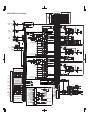
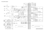
■ M7CL-48/M7CL-32 V2.0 Block Diagram
N
ST O
MATRIX CUE
L R (C) 1 2 ··· 7 8
CASCADE OUT
L R
MIX CASCADE OUT 1-16
To OUTPUT PATCH
To OUTPUT PATCH
CASCADE IN
To OUTPUT PATCH
To OUTPUT PATCH
STEREO CASCADE OUT L,R,MONO (C)
SLOT 1 1-16
SLOT 2 1-16
SLOT 3 1-16
CASCADE
IN
SELECT
+48V MASTER
ON
HA
METER
2
TALKBACK
INPUT TB
AD
3
INPUT 1-32 {48}
TALKBACK
GAIN
ON
INPUT
SELECT
MIX 1-16
OSCILLATOR
OSC
METER
LEVEL
HA
+48V
[INPUT]
[1-32 {48}]
INPUT 1
METER
2
AD
3
Sine Wave
Pink Noise
Burst Noise
INPUT
PATCH
GAIN/TRIM
CH
INSERT OUT 1-32 {48}
CH
INSERT IN 1-32 {48}
HA
+48V
[ST IN]
[1L-4R]
GAIN/TRIM
+48V
HA
METER
2
ST IN R
INSERT POINT
POST ON INSERT OUT
PRE FADER INSERT OUT
PRE EQ INSERT OUT
AD
1
3
HPF
32
{48}
INSERT
ATT
4BAND
EQ
PRE HPF
PRE EQ POST EQ
PRE EQ
INSERT OUT
Keyin
Self PRE EQ
Self POST EQ
MIX13-16 OUT
CH[1-8,9-16,17-24,25-32]POST EQ {32}
CH[1-8,9-16,17-24,25-32,33-40,41-48]POST EQ{48}
GAIN/TRIM
To CASCADE IN
SELECT
DYNA1OUT
EQ OUT
DYNA2OUT
METER
METER
METER
GR METER
GR METER
PRE EQ
METER
PRE HPF
METER
ST IN
1L-4R
To MONITOR
SELECT
GATE
COMP
DUCK
COMPAND
EXPAND
DE-ESSER
COMP
KEYIN CUE
Keyin Filter
To MIX
[SLOT]
SLOT1 1-16
16
SLOT2 1-16
To MIX
SLOT3
16
SLOT3 1-16
PRE EQ / PRE FADER / POST ON
MATRIX OUT
1-8
STEREO OUT
L,R,MONO (C)
RACK2 IN
A (L ) / B (R)
HPF
ATT
PRE HPF
4BAND
EQ
PRE EQ POST EQ
Keyin
Self PRE EQ
Self POST EQ
MIX13-16 OUT
STCH 1L-4R POST EQ
POST ON
31BandGEQ
RACK2 OUT
A (L) / B (R)
ST R
ON
LEVEL
ON
LEVEL
ON
LEVEL
PAN
MATRIX2,4...8
LEVEL
PAN
STEREO
INSERT OUT
L,R,MONO (C)
MATRIX
INSERT OUT
1-8
METER RACK OUT L
METER RACK OUT R
EFFECT
RACK5 IN
A (L) / B (R)
RACK6 IN
A (L) / B (R)
EFFECT CUE
RACK6 (same as RACK5)
RACK5 OUT
A(L) / B (R)
RACK6 OUT
A (L) / B (R)
RACK7 IN
A (L) / B (R)
RACK7 (same as RACK5)
RACK7 OUT
A (L) / B (R)
RACK8 IN
A (L) / B (R)
RACK8 (same as RACK5)
RACK8 OUT
A (L) / B (R)
VARI
PRE FADER / POST ON
To MATRIX
VARI
STEREO
PAN
LR MONO
PAN MODE TO ST TO MONO
LCR
POST ON
PRE EQ
METER
INSERT
EQ OUT
DYNA OUT
METER
METER
GR METER
ATT
COMP
COMPAND
EXPAND
4BAND
EQ
PRE EQ POST EQ
PRE EQ
INSERT OUT
CUE L
CUE R
PRE FADER
METER
LEVEL/
DCA 1-8
GATE
COMP
DUCK
COMPAND
EXPAND
DE-ESSER
COMP
KEYIN CUE
Keyin Filter
To MIX
POST PAN L
POST PAN R
LR MONO TO MONO TO ST
POSTON
METER
ON
POST ON
METER
PRE FADER
METER
LEVEL
BAL
STEREO OUT
L,R,MONO (C)
ON
INSERT
INSERT
POST ON
INSERT OUT
PRE FADER
INSERT OUT PRE FADER
Keyin
Self PRE EQ / Self POST EQ / MIX13-16 OUT /
ST (L,R,MONO (C)) POST EQ
To OUTPUT PATCH
To MONITOR SELECT
POST ON
CUE ON
MATRIX1,3...7
PAN MODE
MONO (C)
TO LCR
LCR
32 {48}
MIX INSERT IN 1-16
16
ON
ON
PRE FADER / POST ON
PAN
To MATRIX
VARI
STEREO
MATRIX 1-8
To RACKIN PATCH
To OUTPUT PATCH MATRIX
INSERT OUT 1-8
PAN LINK
ON
MIX 1,3... 15
ON
MIX 2,4... 16
MATRIX
INSERT IN 1-8
ON
POST PAN L
ON
POST PAN R
ON
LEVEL
ON
LEVEL
To MIX
ON
LEVEL
BAL
ON
LEVEL
MATRIX1,3...7
ON
LEVEL
MATRIX2,4...8
ON
LEVEL
BAL
PRE EQ / PRE FADER / POST ON
PRE EQ / PRE FADER / POST ON
ON
LEVEL
LEVEL
PRE FADER / POST ON To MATRIX
VARI
POST ON
VARI
(PRE FADER)PFL/(POST ON)AFL / POST PAN R
ON
CSR
PRE FADER
POST ON
(PRE FADER)PFL/(POST ON)AFL / POST PAN L
MATRIX2,4...8
ST L
LEVEL
ST R
FIXED
PRE EQ / PRE FADER / POST ON
INSERT POINT
POST ON INSERT OUT
PRE FADER INSERT OUT
PRE EQ INSERT OUT
PRE EQ
METER
INSERT
ATT
EQ OUT
DYNA OUT
METER
METER
GR METER
4BAND
EQ
PRE EQ POST EQ
PRE EQ
INSERT OUT
CUE ON
COMP
COMPAND
EXPAND
PRE FADER
METER
POST ON
METER
LEVEL
ON
MATRIX OUT 1-8
INSERT
INSERT
PRE FADER
PRE FADER
INSERT OUT
Keyin
Self PRE EQ / Self POST EQ / MIX13-16 OUT/
MATRIX1-8 POST EQ
POST ON
INSERT OUT
To OUTPUT PATCH
To MONITOR SELECT
POST ON
(PRE FADER) PFL / (POST ON) AFL
CUE L
CUE TRIM
(INPUT / OUTPUT / DCA)
CUE R
KEYIN CUE
KEYIN CH1-32 {48}
KEYIN ST IN1L-4R
KEYIN CUE
SELECT
ON
RACK 5-8 OUT L / R
EFFECT CUE
SELECT
ON
EFFECT CUE
To CHINSERT IN
MONO
METER CUE L
METER CUE R
CUE R
To MIX INSERT IN
STEREO INSERT IN L,R,MONO (C)
To STEREO INSERT IN
MATRIX INSERT IN 1-8
To MATRIX INSERT IN
CUE ON
CUE LOGIC
ST IN1 L,R
DIRECT OUT 1-32 {48}
MIX OUT 1-16
STEREO OUT L,R,MONO (C)
MATRIX OUT 1-8
MONITOR OUT L,R, MONO (C)
CH INSERT OUT 1-32 {48}
MIX INSERT OUT 1-16
STEREO INSERT OUT L,R,MONO (C)
MATRIX INSERT OUT 1-8
PHONES
LEVEL LINK
ST IN2 L,R
ST IN3 L,R
ST IN4 L,R
MIX CASCADE OUT 1-16
STEREO CASCADE OUT L,R,MONO (C)
MATRIX CASCADE OUT 1-8
CUE CASCADE OUT L,R
Flex15GEQ
To MATRIX
TO LCR
STEREO
INSERT IN L,R,MONO (C)
OUTPUTS
METER RACK IN L
METER RACK IN R
PRE FADER / POST ON
STEREO L,R,MONO(C)
METER RACK OUT
METER RACK OUT A
METER RACK OUT B
POST ON
To RACKIN PATCH
INSERT POIN
To OUTPUT PACH STEREO
POST ON INSERT OUT
PRE FADER INSERT OUT
INSERT OUT L,R,MONO (C)
PRE EQ INSERT OUT
31BandGEQ
METER RACK IN A
METER RACK IN B
POST ON
INSERT OUT
CSR
8
MIX
INSERT OUT
1-16
ON
CUE L
3
METER RACK IN
LEVEL
PAN
MONO (C)
LEVEL
VARI
STEREO
ON
CH INSERT IN 1-32 {48}
RACK5
CH
INSERT OUT
1-32 {48}
ON
MIX2,4...16
ON
To MATRIX
RACK1 OUT
A (L) / B (R)
RACK4 OUT
A (L) / B (R)
LEVEL
MIX1,3...15
VARI
METER RACK OUT A
METER RACK OUT B
RACK4 (same as RACK1)
MATRIX2,4...8
ON
To MATRIX PRE EQ / PRE FADER / POST ON
RACK4 IN
A (L) / B (R)
ON
ON
VARI
STEREO
RACK3 OUT
A (L) / B (R)
LEVEL
ST L
PAN LINK
ON
PRE EQ / PRE FADER / POST ON
To MIX
METER RACK OUT
RACK3 (same as RACK1)
MATRIX1,3...7
CSR
To MATRIX
DYNA1OUT
EQ OUT
DYNA 2OUT
METER
METER
METER
GR METER
GR METER
PRE EQ
METER
PRE HPF
METER
RACK1
RACK3 IN
A (L) / B (R)
PRE FADER
INSERT OUT PRE FADER
Keyin
Self PRE EQ / Self POST EQ / MIX13-16 OUT/
MIX(1-8,9-16)POST EQ
(13-16)To KEYIN
To RACKIN PATCH
To OUTPUT PATCH
To MONITOR SELECT
MIX OUT1-16
ST R
MATRIX1,3...7
To MIX
RACK2 (same as RACK1)
INSERT
(PRE FADER) PFL / (POST ON) AFL
RACK
Flex15GEQ
ON
INSERT
(PRE FADER) PFL / (POST ON) AFL
ST L
MONO (C)
LEVEL
FIXED
STEREO
RACK1 IN
A (L ) / B (R)
CUE ON
BAL
STCH 1L-4R
SLOT1 1-16
SLOT2 1-16
SLOT3 1-16
MIX OUT
1-16
PAN MODE
ON
(PRE FADER)PFL / (POST ON)AFL/POST PAN R
INSERT
IN
PATCH
METER RACK IN A
METER RACK IN B
PRE EQ POST EQ
PRE EQ
INSERT OUT
To MATRIX PRE EQ / PRE FADER / POST ON
VARI
ON
COMP
COMPAND
EXPAND
4 BAND
EQ
LEVEL
ON
PRE EQ / PRE FADER / POST ON
(PRE FADER)PFL / (POST ON)AFL/POST PAN L
ATT
POST ON
METER
PRE FADER
METER
ON
POST PAN R
VARI
STEREO
ON
DYNA OUT
EQ OUT
METER
METER
GR METER
PRE EQ
METER
To OUTPUT PATCH
TO LCR
LCR
POST ON
INSERT OUT
VARI
STEREO
8
METER RACK IN
PRE FADER
PRE FADER
INSERT OUT
VARI
RACK1 OUT
A (L) / B (R)
RACK2 OUT
A (L) / B (R)
RACK3 OUT
A (L) / B (R)
RACK4 OUT
A (L) / B (R)
RACK5 OUT
A (L) / B (R)
RACK6 OUT
A (L) / B (R)
RACK7 OUT
A (L) / B (R)
RACK8 OUT
A (L) / B (R)
RACK
IN
PATCH
ON
INSERT
POST PAN L
To MIX
SLOT2
DIRECT OUT 1-32 {48}
LEVEL
POST PAN L
POST PAN R
POST ON
METER LR MONO TO MONO TO ST
INSERT
POST ON
To MIX
16
PRE FADER
METER
LEVEL/
DCA1-8
FIXED
FIXED
STEREO
SLOTIN SLOTIN SLOTIN
METER METER METER
SLOT1
ON
PRE HPF / PRE EQ / PRE FADER / POST ON
PAN
METER
AD
3
MIX
INSERT IN 1-16
HPF LPF
INSERT
To RACKIN PATCH
To OUTPUT PATCH
2
ON
INPUT
1-32 {48}
CH 1-32 {48}
ST IN L 1
INSERT POINT
To RACKIN PATCH
POST ON INSERT OUT
To OUTPUT PATCH
MIX
PRE FADER INSERT OUT
INSERT OUT 1-16
PRE EQ INSERT OUT
Tip
PHONES OUT LR
Ring
DA
2
Sleeve
[PHONES]
ST IN1 L,R
ST IN2 L,R
ST IN3 L,R
ST IN4 L,R
PHONES LEVEL
OUTPUT
PATCH
ATT
DELAY
METER
DELAY
SLOT1
16
METER
SLOT2OUT
METER
SLOT3OUT
(MAX:600ms)
SLOT3
16
DIRECT OUT 1-32 {48}
MIX OUT 1-16
STEREO OUT L,R,MONO (C)
MATRIX OUT 1-8
MONITOR OUT L,R,MONO (C)
OUTPUT
PATCH
DELAY
(MAX:600ms)
METER OMINI OUT
MIX OUT 1-16
STEEREO OUT L,R,MONO (C)
MATRIX OUT 1-8
MONITOR OUT L,R,MONO (C)
OUTPUT
PATCH
DELAY
(MAX:600ms)
METER
ATT
[SLOT]
SLOT2
16
(MAX:600ms)
DELAY
TRIM
SLOT1OUT
(MAX:600ms)
TRIM
2
DA
1
16
ATT
3
[OMNI OUT] (1-16)
TRIM
2TR OUT
2
DIT
AES / EBU
STEREO OUT L,R
STEREO OUT MONO (C)
STEREO OUT L,C,R
[2TR OUT DIGITAL]
STEREO OUT
L,R
STEREO OUT
MONO (C)
MIX OUT1-16
MATRIX OUT1-8
DEFINE
MIX
(MAX : 8ch)
DELAY
(MAX:600ms)
DELAY
(MAX:600ms)
MONITOR SELECT
TALKBACK 1
INPUT
To OUTPUT PATCH
To OUTPUT PATCH
To OUTPUT PATCH
To OUTPUT PATCH
CUE CASCADE OUT LR
+48V
[TALKBACK
INPUT]
To OUTPUT PATCH
To OUTPUT PATCH
MONO
MONITOR L
METER MONITOR L
MONITOR R
METER MONITOR R
MONITOR MONO (C)
METER MONITOR MONO (C)
DIMMER
+48V
MATRIX CASCADE OUT1-8
To OUTPUT PATCH
To OUTPUT PATCH
To OUTPUT PATCH
ON
TALKBACK ON
MONITOR DIMM ON
MONITOR MONITOR
LEVEL
FADER
+MONO (C)
PHONES L
To PHONES OUT
PHONES R
To PHONES OUT
DELAY
(MAX:600ms)
MONITOR OUT L
DELAY
(MAX:600ms)
MONITOR OUT R
DELAY
(MAX:600ms)
MONITOR OUT MONO (C)
An output port delay becomes invalid by
assigning a monitor out to the output port
To OUTPUT PATCH
To OUTPUT PATCH
To OUTPUT PATCH
m7cl_mixing_parameter.fm Page 1 Friday, June 19, 2009 11:33 AM
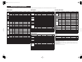
Mixing parameter operation applicability
This table indicates how the behaviors of each of the input channel and output channel parameters are affected by Stereo, Link, Recall Safe, and User Level settings.
■ Input Channels
Parameter
Gain
HA
■ Mix Channels
Stereo
*1
O
CHANNEL LINK
INPUT HA
Direct
Out
USER LEVEL
Channel
Library
OUTPUT NAME
O
MIX ALL
MIX PROCESSING
O
+48V
INPUT HA
INPUT HA
O
O
MIX ALL
MIX PROCESSING
O
INPUT NAME
INPUT NAME
O
Att
O
MIX ATT
MIX PROCESSING
O
On
INPUT ALL
INPUT PROCESSING
O
EQ
O
MIX EQ
MIX PROCESSING
O
Point
INPUT ALL
INPUT PROCESSING
O
MIX DYNA1
MIX PROCESSING
On, Level
INPUT ALL
INPUT PROCESSING
O
Point
INPUT ALL
INPUT PROCESSING
O
INPUT EQ
INPUT ATT
INPUT PROCESSING
O
INPUT EQ
INPUT PROCESSING
O
EQ
O
INPUT EQ
INPUT EQ
INPUT PROCESSING
O
INPUT DYNA1
INPUT PROCESSING
Key-In Source
Key-In Filter
O
INPUT
DYNAMICS1
INPUT DYNA1
INPUT PROCESSING
O
Others
O
INPUT
DYNAMICS1
INPUT DYNA1
INPUT PROCESSING
O
INPUT DYNA2
INPUT PROCESSING
INPUT DYNA2
INPUT PROCESSING
O
INPUT FADER/ON *4
O
Key-In Source
INPUT
DYNAMICS2
Others
O
On
O
INPUT MIX ON *2 INPUT MIX ON
Level
O
INPUT MIX SEND
Pan/Balance
O
*2
INPUT MIX SEND
INPUT FADER/ON *4
O
INPUT MIX SEND
INPUT FADER/ON *4
O
On
Insert
Point
Dynamics1
Others
O
MIX DYNA1
MIX PROCESSING
O
On
O
MIX to MATRIX ON
MIX FADER/ON *4
O
Level
O *5
MIX to MATRIX SEND
MIX FADER/ON *4
O
Pan/Balance
O
MIX to MATRIX SEND
MIX FADER/ON *4
O
Pre/Post
O
MIX to MATRIX SEND MIX PROCESSING
O
To Stereo/Mono
O
MIX ALL
MIX PROCESSING
O
Pan/Balance
O
MIX ALL
MIX FADER/ON
O
On
O
MIX ALL
MIX PROCESSING
O
CSR
O
MIX ALL
MIX PROCESSING
O
On
O
MIX ON
MIX FADER/ON
O
Fader
O
MIX FADER
MIX FADER/ON
O
On
WITH MIX SEND
WITH MIX SEND *4
Level
WITH MIX SEND
WITH MIX SEND *4
Pan
WITH MIX SEND
WITH MIX SEND *4
WITH MIX SEND
WITH MIX SEND *4
MIX ALL
MUTE ASSIGN
To Matrix
LCR
From Input
Pre/Post
INPUT PROCESSING
O
■ Matrix Channels
Parameter
INPUT ALL
INPUT PROCESSING
O
INPUT ALL
INPUT PROCESSING
O
On
O
INPUT ON
INPUT ON
INPUT FADER/ON
O
Fader
O
INPUT FADER
INPUT FADER
INPUT FADER/ON
O
Mute Assign
O
INPUT ALL
MUTE GROUP ASSIGN
O
DCA Assign
O
INPUT ALL
DCA GROUP ASSIGN
O
Cue
O
Mute Safe
O
Recall Safe
O
Fade Time, On
O
STORE
O
STEREO, MONO EQ
STEREO, MONO
PROCESSING
O
STEREO, MONO
DYNA1
STEREO, MONO PROCESSING
O
STEREO, MONO
DYNA1
STEREO, MONO PROCESSING
O
On
O
STEREO, MONO to
MATRIX ON
STEREO, MONO FADER/
ON *4
O
Level
O *5
STEREO, MONO to
MATRIX SEND
STEREO, MONO FADER/
ON *4
O
Pan/Balance
O
STEREO, MONO to
MATRIX SEND
STEREO, MONO FADER/
ON *4
O
Pre/Post
O
STEREO, MONO to
MATRIX SEND
STEREO, MONO PROCESSING
O
Balance
O
STEREO, MONO ALL
STEREO, MONO FADER/
ON
O
On
O
STEREO, MONO ON
STEREO, MONO FADER/
ON
O
O
STEREO, MONO FADER/
STEREO, MONO FADER
ON
O
STEREO, MONO ALL
MUTE ASSIGN
O
STORE
O
Key-In Source
Dynamics1
Others
To Matrix
O
INPUT MATRIX
SEND
O
O
O
O
O
EQ
Fade Time, On
INPUT FADER/ON *4
CSR
O
O
INPUT MATRIX
SEND
On
STEREO, MONO PROCESSING
Recall Safe
O
O
STEREO, MONO ATT
Mute Safe
INPUT FADER/ON *4
O
O
O
INPUT MATRIX
SEND
INPUT FADER/ON
Att
Fade Time, On
INPUT MATRIX
SEND *3
INPUT PROCESSING
O
O
O
INPUT ALL
STEREO, MONO PROCESSING
O
Level
INPUT ALL
STEREO, MONO ALL
Cue
O
O
O
Mute Assign
INPUT FADER/ON *4
O
Point
Insert
O
INPUT MATRIX
ON
To Stereo/ Mono
O
O
INPUT MATRIX
ON *3
Pan/ Balance
O
STEREO, MONO PROCESSING
Recall Safe
O
O
OUTPUT NAME
STEREO, MONO ALL
Mute Safe
On
Linked in
stereo mode
Name, Icon
Insert
On
O
Point
STORE
RECALL SAFE
USER LEVEL
O
O
Channel
Library
OUTPUT NAME
OUTPUT NAME
O
MATRIX ALL
MATRIX PROCESSING
O
O
MATRIX ALL
MATRIX PROCESSING
O
Att
O
MATRIX ATT
MATRIX PROCESSING
O
EQ
O
MATRIX EQ
MATRIX PROCESSING
O
MATRIX DYNA1
MATRIX PROCESSING
Dynamics1
Key-In Source
Others
O
MATRIX DYNA1
MATRIX PROCESSING
O
Balance
O
MATRIX ALL
MATRIX FADER/ON
O
On
O
MATRIX ON
MATRIX FADER/ON
O
O
Fader
From Input
From Mix
From Stereo/Mono
MATRIX FADER
MATRIX FADER/ON
On
O
WITH MATRIX SEND
WITH MATRIX SEND *4
Level
WITH MATRIX SEND
WITH MATRIX SEND *4
Pan
WITH MATRIX SEND
WITH MATRIX SEND *4
Pre/Post
WITH MATRIX SEND
WITH MATRIX SEND *4
MATRIX ALL
MUTE ASSIGN
O
STORE
O
Mute Assign
O
Cue
O
Mute Safe
O
Recall Safe
O
Fade Time, On
O
Channel
Library
OUTPUT NAME
Fader
O
USER LEVEL
O
O
INPUT PROCESSING
RECALL SAFE
On
Name, Icon
Cue
INPUT MIX
SEND
INPUT MATRIX
SEND *3
Linked on the
STEREO channel
O
INPUT MIX
SEND *2
O
Parameter
Mute Assign
O
Pan/Balance
O
Key-In Source
Pre/Post
Pre/Post
LCR
OUUTPUT NAME
O
O
INPUT EQ
To
Matrix
Channel
Library
INPUT HA
O
To Mix
USER LEVEL
INPUT HA
O
Name, Icon
RECALL SAFE
INPUT HA
Att
Dyna
mics2
Linked in
stereo mode
INPUT HA
HPF
Dyna
mics1
Parameter
Phase
Name, Icon
Insert
RECALL SAFE
■ STEREO, MONO Channels
■ DCA
Parameter
RECALL SAFE
USER LEVEL
Name, Icon
DCA ALL
DCA MASTER ON
On
DCA LEVEL/ON
DCA MASTER ON
Fader
DCA LEVEL/ON
Fade Time, On
DCA MASTER ON
STORE
*1Linked parameters on ST IN Channels 1-4.
*2Applies to parameters for which the MIX channel 1_16 individual Send Parameter setting and the item in the
table are both enabled.
*3Applies to parameters for which the MATRIX channel 1_8 individual Send Parameter setting and the item in
the table are both enabled.
*4User operation is allowed if the send-source channel’s “FADER/ON” is ON and the send-destination channel’s
“WITH SEND” is ON.
*5Linked if the send-destination channel is Stereo.
Yamaha Pro Audio global web site:
http://www.yamahaproaudio.com/
Yamaha Manual Library
http://www.yamaha.co.jp/manual/
U.R.G., Pro Audio & Digital Musical Instrument Division, Yamaha Corporation
© 2009 Yamaha Corporation
WS66170 906POCP1.3-01A0
Printed in Japan