1
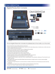
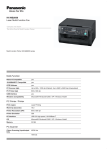
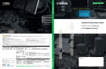
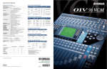
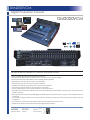
DM2000VCM
Digital Production Console
DM2000VCM
Rear Panel
*Peak Meter Bridge MB2000 & Wood Side Pad SP2000 are options.
96 Inputs and 22 Buses For Glorious Surround Sound.
• Precise 24-bit/96-kHz audio and high-performance head amps.
• 96-input 22 buses (8 group buses, 12 auxiliary buses, and a stereo bus) mix capacity at 96kHz.
• Powerful channel functions with flexible control and digital patching capability.
• Eight advanced multi-effect processors plus six 31-band GEQs.
• Scene memory and auto-mix functions for efficient workflow.
• Versatile channel pairing and grouping functions enhance mixing efficiency.
• Comprehensive interface with touch-sensitive 100-mm motor faders.
• Six mini-YGDAI expansion slots for easy I/O expansion in a variety of formats.
• Compatible with both Windows or Macintosh versions of Studio Manager version2 Software, allowing your PC and Console to work
together seamlessly.
• Easy integration with computer-based DAWs (Digital Audio Workstations) or digital recorders to create an advanced digital production
environment.
• A comprehensive range of features for surround production, including an enhanced surround monitoring environment with bass
management.
• A new dimension of production power with the addition of Yamaha VCM effects and processing.
• Included in the THX pm3™ Studio Certification Program Approved Equipment List.
OPTIONS
MB2000
SP2000
LA1L
Peak Meter Bridge
Side Pad
Gooseneck Lamp
DM2000VCM
GENERAL SPECIFICATIONS
ANALOG INPUT SPECIFICATIONS
Internal processing
32bit (Accumulator=58bit)
Number of scene memories
Sampling frequency rate
99
Internal : 44.1kHz, 48kHz, 88.2kHz, 96kHz
Input terminal
External: Normal rate 44.1kHz (-10%) to 48kHz (+6%)
Total harmonic distortion*1
CH INPUT to STEREO OUT
Input Gain=Min.
Frequency response
CH INPUT to STEREO OUT
Dynamic range
(maximum level to noise level)
Hum & noise level*
2
(20Hz to 20kHz)
Rs=150ohms
Input Gain=Max
Input Pad=0dB
Input Sensitivity=-60dB
Crosstalk (@1kHz)
Input Gain=Min.
Phantom Power
Power requirements
Power consumption
Dimensions (W x H x D)
Weight
0
CH INPUT
A/B 1-24
Double rate 88.2kHz (-10%) to 96kHz (+6%)
Signal Delay
Actual
source
GAIN impedance
PAD
Less than 2.3 ms CH INPUT to STEREO OUT (@fs=48 kHz)
Less than 1.2 ms CH INPUT to STEREO OUT (@fs=96 kHz)
Less than 0.05%, 20Hz to 20kHz @+14dBu into 600Ω
Less than 0.01%, 1kHz @+18dBu into 600Ω
(@fs=48kHz)
Less than 0.05%, 20Hz to 40kHz @+14dBu into 600Ω
Less than 0.01%, 1kHz @+18dBu into 600Ω
(@fs=96kHz)
20Hz - 20kHz, 0.5, -1.5dB, @+4dBu into 600Ω (@fs=48kHz)
20Hz - 40kHz, 0.5, -1.5dB, @+4dBu into 600Ω (@fs=96kHz)
110dB typ, DA Converter (STEREO OUT)
108dB typ, AD+DA (to STEREO OUT) (@fs=48kHz)
106dB typ, AD+DA (to STEREO OUT) (@fs=96kHz)
-128dBu Equivalent Input Noise
-92dBu residual output noise. STEREO OUT(STEREO OUT off)
-92dBu(96dB S/N) STEREO OUT(STEREO fader at nominal
level and all CH INPUT faders at minimum level)
-64dBu(68dB S/N) STEREO OUT(STEREO fader at nominal level
and one CH INPUT fader at nominal level)
80dB adjacent input channels (CH1-24)
80dB input to output
+48V
Japan: AC100V 50/60Hz
North America: AC120V, 60Hz
Other Areas: AC220-240V, 50/60Hz
300W
DM2000: 906 x 257 x 821mm (35.7" x 10.2" x 32.3")
With MB & SP: 968 x 371 x 883mm (38.1" x 14.6" x 34.8")
DM2000: 43.0kg (94.8lbs)
With MB & SP: 51.6kg (113.8lbs)
*1 Total harmonic distortion is measured with a 18dB/Oct filter @80kHz.
*2 Hum & noise level is measured with a 6dB/oct filter @12.7kHz; equivalent to 20kHz filter with
infinite dB/Oct attenuation.
-60dB
26
3kΩ
-16dB
Sensitivity
Nominal
-70dBu
-60dBu
Max.
before clip
-46dBu
50-600Ω Mics
& 600Ω Lines
-26dBu
-16dBu
-2dBu
0dBu
+10dBu
+24dBu
Connector
A:XLR3-31 type*
B:TRS Phone
Jack*
INSERT IN 1-24
10kΩ
600Ω Lines
-6dBu
+4dBu
+18dBu
TRS Phone Jack*
2TR IN ANALOG 1[L,R]
10kΩ
600Ω Lines
+4dBu
+4dBu
+18dBu
TRS Phone Jack*
2TR IN ANALOG 2[L,R]
10kΩ
600Ω Lines
-10dBu
-10dBV
+4dBV
RCA Pin Jack**
ANALOG OUTPUT SPECIFICATIONS
For use with
nominal
GAIN SW
600Ω
10kΩ Lines
—
Output terminals
Connector
Max.
before clip
-10dBV
+4dBV RCA Pin Jack**
75Ω
600Ω Lines
—
+4dBu
+18dBu
XLR3-32 type*
STUDIO MONITOR
OUT[L,R]
75Ω
10kΩ Lines
—
+4dBu
+18dBu
TRS Phone Jack*
C-R MONITOR OUT
LARGE[L,R]
75Ω
600Ω Lines
—
+4dBu
+18dBu
XLR3-32 type*
C-R MONITOR OUT
SMALL[L,R]
75Ω
600Ω Lines
—
+4dBu
+18dBu
XLR3-32 type*
10kΩ Lines
+18dB
(default)
+4dB
+4dBu
+18dBu
-10dBu
+4dBu
10kΩ Lines
—
+4dBu
+18dBu
8Ω Phones
—
4mW
25mW
40Ω Phones
—
12mW
75mW
Actual source
impedance
Output terminal
STEREO OUT[L,R]
OMNI OUT 1-8
75Ω
INSERT OUT 1-24
75Ω
PHONES
100Ω
Nominal
TRS Phone Jack*
TRS Phone Jack*
ST Phone Jack**
DIGITAL INPUT SPECIFICATIONS
Terminal
DIMENSIONS
unit : mm
2TR IN DIGITAL
Format
Data length
Level
1
AES/EBU
24bit
RS422
XLR3-31 type
2
AES/EBU
24bit
RS422
XLR3-31 type
3
IEC-60958
24bit
0.5Vpp/75Ω
RCA Pin Jack
—
—
RS422
CASCADE IN
371
247
Input level
For use with
nominal
Connector
D-sub Half Pitch Connector
68Pin (Female)
906 (Screw heads included)
DIGITAL OUTPUT SPECIFICATIONS
883
821
Terminal
2TR OUT DIGITAL
Format
Data length
Level
1
AES/EBU
(Professional use)
24bit
RS422
XLR3-32 type
2
AES/EBU
(Professional use)
24bit
RS422
XLR3-32 type
3
IEC-60958
(Consumer Use)
24bit
—
—
CASCADE OUT
900 (Screw heads NOT included)
968
Connector
0.5Vpp/75Ω RCA Pin Jack
RS422
D-sub Half Pitch Connector
68Pin (Female)
CONTROL I/O SPECIFICATIONS
Terminal
TO HOST
MIDI
TIME CODE IN
Serial
Format
—
Level
RS422
Connector
Mini DIN Connector 8P
USB
B Type USB Connector
USB1.1
0 V~3.3 V
IN
MIDI
—
DIN Connector 5P
OUT
MIDI
—
DIN Connector 5P
THRU
MIDI
—
DIN Connector 5P
MTC
MIDI
—
SMPTE
Nominal –10dB/10kΩ
XLR3-31 Type*
SMPTE
DIN Connector 5P
IN
—
TTL/75Ω (ON/OFF)*1
BNC Connector
OUT 1, 2
—
Nominal –10dB/10kΩ
BNC Connector
CONTROL
—
Open collector
REMOTE
—
RS422
PS/2
—
DIN Connector 6P
SmartMedia slot
WORD CLOCK
KEYBOARD
D-Sub Connector 25P (Female)
D-Sub Connector 9P (Male)
STORAGE CARD
—
—
METER
—
RS422
D-SUB Connector 15P (Female)
LAMP (with MB2000)
—
0-12V
XLR4-31 Type
*1. This switch is on the rear panel.
DM2000VCM
BLOCK DIAGRAM