1
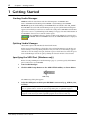
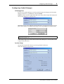
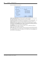
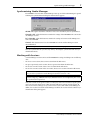
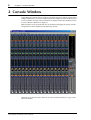
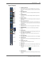
Studio Manager
for
Owner’s Manual
E
2
Important Information
Special Notices
•
•
•
•
•
•
•
The software and this owner’s manual are the exclusive copyrights of Yamaha Corporation.
Copying of the software or reproduction of this manual in whole or in part by any means is
expressly forbidden without the written consent of the manufacturer.
Yamaha makes no representations or warranties with regard to the use of the software and
documentation and cannot be held responsible for the results of the use of this manual and
the software.
This disc is a CD-ROM. Do not attempt to play the disc on an audio CD player. Doing so
may result in irreparable damage to your audio CD player.
Copying of the commercially available music sequence data and/or digital audio files is
strictly prohibited except for your personal use.
The screen displays as illustrated in this owner’s manual are for instructional purposes, and
may appear somewhat different from the screens which appear on your computer.
Future upgrades of application and system software and any changes in specifications and
functions will be announced separately.
Trademarks
Adobe, Acrobat, and Reader are registered trademarks of Adobe Systems Incorporated.
Apple, AppleTalk, and Macintosh are registered trademarks of Apple Computer, Inc.
Microsoft and Windows are registered trademarks of Microsoft Corporation. OMS is a registered trademark of Opcode Systems, Inc. PowerPC is a registered trademark of International Business Machines Corporation. All other trademarks are the property of their
respective holders and are hereby acknowledged.
Copyright
No part of the Studio Manager software or its documentation may be reproduced or distributed in any form or by any means without the prior written authorization of Yamaha
Corporation.
© 2003 Yamaha Corporation. All rights reserved.
Yamaha Web Site
Information about Studio Manager, related products, and other Yamaha professional audio
equipment is available on the Yamaha Professional Audio Web site at:
http://www.yamahaproaudio.com/
Specifications and external appearance subject to change without notice.
Studio Manager for DM1000—Owner’s Manual
3
Contents
1
Getting Started . . . . . . . . . . . . . . . . . . . . . . . . . . . . 4
Starting Studio Manager . . . . . . . . . . . . . . . . . . . . . . . . . . . . . . . . . . . . . . . . . . . . . . . 4
Quitting Studio Manager . . . . . . . . . . . . . . . . . . . . . . . . . . . . . . . . . . . . . . . . . . . . . . 4
Specifying the MIDI Port (Windows only) . . . . . . . . . . . . . . . . . . . . . . . . . . . . . . . . 4
Configuring Studio Manager . . . . . . . . . . . . . . . . . . . . . . . . . . . . . . . . . . . . . . . . . . . 5
Synchronizing Studio Manager . . . . . . . . . . . . . . . . . . . . . . . . . . . . . . . . . . . . . . . . . 7
Working with Sessions . . . . . . . . . . . . . . . . . . . . . . . . . . . . . . . . . . . . . . . . . . . . . . . . 7
2
Console Window . . . . . . . . . . . . . . . . . . . . . . . . . . . 8
Input Channels . . . . . . . . . . . . . . . . . . . . . . . . . . . . . . . . . . . . . . . . . . . . . . . . . . . . . . 9
Master Section . . . . . . . . . . . . . . . . . . . . . . . . . . . . . . . . . . . . . . . . . . . . . . . . . . . . . . 11
Output Channels . . . . . . . . . . . . . . . . . . . . . . . . . . . . . . . . . . . . . . . . . . . . . . . . . . . . 12
Remote Channels . . . . . . . . . . . . . . . . . . . . . . . . . . . . . . . . . . . . . . . . . . . . . . . . . . . 13
3
Selected Channel Window . . . . . . . . . . . . . . . . . . 14
Input Channels . . . . . . . . . . . . . . . . . . . . . . . . . . . . . . . . . . . . . . . . . . . . . . . . . . . . .
Bus Outs . . . . . . . . . . . . . . . . . . . . . . . . . . . . . . . . . . . . . . . . . . . . . . . . . . . . . . . . . . .
Aux Sends . . . . . . . . . . . . . . . . . . . . . . . . . . . . . . . . . . . . . . . . . . . . . . . . . . . . . . . . . .
Stereo Out . . . . . . . . . . . . . . . . . . . . . . . . . . . . . . . . . . . . . . . . . . . . . . . . . . . . . . . . .
Remote Channels . . . . . . . . . . . . . . . . . . . . . . . . . . . . . . . . . . . . . . . . . . . . . . . . . . .
14
16
18
19
20
4
Library Window . . . . . . . . . . . . . . . . . . . . . . . . . . . 21
5
Patch Editor Window . . . . . . . . . . . . . . . . . . . . . . 23
INPUT PATCH Page . . . . . . . . . . . . . . . . . . . . . . . . . . . . . . . . . . . . . . . . . . . . . . . .
OUTPUT PATCH Page . . . . . . . . . . . . . . . . . . . . . . . . . . . . . . . . . . . . . . . . . . . . . .
INSERT PATCH Page . . . . . . . . . . . . . . . . . . . . . . . . . . . . . . . . . . . . . . . . . . . . . . . .
EFFECT PATCH Page . . . . . . . . . . . . . . . . . . . . . . . . . . . . . . . . . . . . . . . . . . . . . . .
DIRECT OUT PATCH Page . . . . . . . . . . . . . . . . . . . . . . . . . . . . . . . . . . . . . . . . . .
23
24
25
26
27
6
Surround Editor Window . . . . . . . . . . . . . . . . . . . 28
7
Timecode Counter Window . . . . . . . . . . . . . . . . . 29
8
Effect Editor Window . . . . . . . . . . . . . . . . . . . . . . 30
9
Keyboard Shortcuts . . . . . . . . . . . . . . . . . . . . . . . . 31
File Menu . . . . . . . . . . . . . . . . . . . . . . . . . . . . . . . . . . . . . . . . . . . . . . . . . . . . . . . . . . 31
Windows Menu . . . . . . . . . . . . . . . . . . . . . . . . . . . . . . . . . . . . . . . . . . . . . . . . . . . . . 31
Index . . . . . . . . . . . . . . . . . . . . . . . . . . . . . . . . . . . . . . 32
Studio Manager for DM1000—Owner’s Manual
4
Chapter 1—Getting Started
1 Getting Started
Starting Studio Manager
Windows: Click the Start button and then click Programs–>YAMAHA OPT
Tools–>YAMAHA Studio Manager for DM1000–>Studio Manager for DM1000.
Macintosh: Open the Studio Manager for DM1000 folder and double-click “SM_DM1K.”
If a DM1000 is detected while Studio Manager starts up, the Synchronization dialog box
appears, from which you can choose to transfer the settings of the DM1000 to Studio Manager or vice versa. See “Synchronizing Studio Manager” on page 7 for more information. If
no DM1000 is detected, a new Console window opens.
The ONLINE indicator is displayed while Studio Manager is connected to a
DM1000. When no DM1000 is detected, the OFFLINE indicator is displayed.
Quitting Studio Manager
Choose Exit (Quit on the Macintosh) from the File menu.
If there are no unsaved changes, all windows close and Studio Manager quits. If there are
unsaved changes, a message asking whether or not you want to save the changes appears.
Click Yes to save the changes and quit, click No to quit, or click Cancel to cancel the operation. Studio Manager can also be quit by clicking the Console window’s Close button.
Specifying the MIDI Port (Windows only)
1
Before selecting a MIDI port in Studio Manager (page 5), you must specify which MIDI
port is connected to your DM1000.
Start Studio Manager.
2
Click the MIDI Setup button on the MIDI SETUP toolbar, as shown below.
MIDI Setup
The MIDI Setup dialog box appears.
3
Select the MIDI port to which your DM1000 is connected (e.g., MIDI In, Out,
or Thru).
Note: To use a MIDI port with Studio Manager, you must select it on the MIDI Setup dialog
box (as explained above) and on the System Setup dialog box, as explained on page 5.
Warning: Studio Manager does not yet support OPT (Open Plug-in Technology), so even if
it appears in the menu of an OPT compatible program, do not start it in this way.
Studio Manager for DM1000—Owner’s Manual
Configuring Studio Manager
5
Configuring Studio Manager
Selecting Ports
In order to use Studio Manager, you must specify the input and output ports that Studio
Manager should use to communicate with the DM1000.
Windows: Choose System Setup from the File menu, and specify the input and output ports
on the Setup dialog box, as shown below.
Macintosh: Choose Select OMS Ports from the File menu, and specify the input and output
ports (device names set in OMS Studio Setup) on the Setup dialog box, as shown below.
Note: Choose OMS MIDI Setup from the File menu, and make sure that the “Run MIDI in
Background” option is on.
OMS Studio Setup can be opened directly from Studio Manager by selecting OMS Studio
Setup from the File menu.
System Setup
To open the Setup window, choose System Setup from the File menu.
This is the Windows Setup window.
Studio Manager for DM1000—Owner’s Manual
6
Chapter 1—Getting Started
This is the Macintosh Setup window
Input Port/Output Port: (Windows only) These pop-up menus are used to select the
ports with which Studio Manager communicates with the DM1000.
Console Device ID: Studio Manager can control any one of up to eight DM1000s, each
with its own exclusive ID. Select the ID of the DM1000 that you want to control.
Channel Select: These options determine whether or not channel selection is linked.
When the PC–>Console option is on, selecting a channel on Studio Manager selects the
same channel on the DM1000. When the Console–>PC option is on, selecting a channel on
the DM1000 selects the same channel on Studio Manager.
Confirmation: These options determine whether or not a confirmation dialog box
appears when storing, recalling, or patching.
Layer Select: These options determine whether or not Layer selection is linked. When the
PC–>Console option is on, selecting a Layer on Studio Manager selects the same Layer on
the DM1000. When the Console–>PC option is on, selecting a Layer on the DM1000 selects
the same Layer on Studio Manager.
Studio Manager for DM1000—Owner’s Manual
Synchronizing Studio Manager
7
Synchronizing Studio Manager
If a DM1000 is detected while Studio Manager starts up, or while Studio Manager is up and
running, the Synchronization dialog box shown below appears.
All Lib: This option determines whether or not Scene and Library data is synchronized.
Console–>PC: Click this button to transfer the settings of the DM1000 to the current Studio Manager Session.
PC–>Console: Click this button to transfer the settings of current Studio Manager Session to the DM1000.
Cancel: Click this button to leave the DM1000 and current Studio Manager Session
unsynchronized.
Note: Do not operate the DM1000 while synchronization is in progress.
You can resynchronize the system at any time by choosing Re-synchronize from the Synchronization menu.
Working with Sessions
•
•
•
A Studio Manager Session consists of all DM1000 mix settings, including Scene and library
data.
To create a new Session, choose New Session from the File menu.
To open a previously saved Session, choose Open Session from the File menu.
To save the current Session, choose Save Session from the File menu.
•
To save the current Session with a new name, choose Save Session as from the File menu.
Note: In order to save the current Automix, or the settings of an optional Y56K card, in a Session, you must resynchronize Studio Manager beforehand (Console–>PC).
Note: In order to protect the communication port used by Studio Manager, DM1000 communication settings (e.g., MIDI, Remote Layer, Machine Control) are not affected by PC–>Console synchronization operations.
Only one Session can be open at a time, so when you create a new Session, or open a previously saved Session, the message “This operation will purge current session” appears. If
there are no unsaved changes, or you do not want to save, click OK. If Studio Manager is
offline, the Session is loaded. If Studio Manager is online, the Session is loaded and the synchronization dialog box appears.
Studio Manager for DM1000—Owner’s Manual
8
Chapter 2—Console Window
2 Console Window
Studio Manager’s Console window displays 16 channel strips and a master section. When
an Input Channel Layer is selected, 16 Input Channels are displayed. When the Master Layer
is selected, the Bus Out and Aux Send channels are displayed. And when the Remote layer
is selected, Remote Channels are displayed.
Many functions can be operated from here by clicking and dragging the various controls
and parameters. This is explained in the following sections.
Channels can be viewed in more detail on the Selected Channel window. See page 14 for
more information.
Studio Manager for DM1000—Owner’s Manual
Input Channels
9
Input Channels
1
B
C
D
5
6
7
8
9
J
K
L
M
N
O
P
Q
A SOURCE parameter
This parameter is used to select an Input source. To select an
Input source, click the parameter and choose from the list that
appears.
B Routing buttons
These buttons are used to route the Input Channel to the Bus
Outs.
C STEREO button
This button is used to route the Input Channel’s signal to the
Stereo Out.
D DIRECT button
This button turns on and off the Input Channel’s routing to its
Direct Out.
E Direct Out parameter
This parameter is used to select the Direct Out destination. To
select a destination, click the parameter and choose from the list
that appears.
F PHASE button
R
This button is used to reverse the signal phase of the channel.
G INSERT button
S
T
This button is used to turn on and off the Input Channel’s
Insert.
H GATE button
V
U
W
X
Y
Z
This button is used to turn on and off the Input Channel’s Gate.
I Gate open/close indicators
These indicators display whether the Gate is open (green) or
closed (red).
J Gate threshold
This displays the Gate Threshold, which can be set by dragging.
a
K COMP button
This button is used to turn on and off the Input Channel’s Compressor.
L Compressor curve
b
This display shows the Compressor’s curve.
M EQ button
This button is used to turn on and off the Input Channel’s EQ.
N EQ curve
This display shows the Equalizer’s curve, which can be set by
dragging.
O DELAY button
This button is used to turn on and off the Input Channel’s Delay
function.
Studio Manager for DM1000—Owner’s Manual
10
Chapter 2—Console Window
P Delay parameter
This parameter is used to set the delay time of the Delay function. Delay times can be set by
dragging.
Q Channel number
This is the channel number.
R AUX section
These controls are used to set the levels of the Aux Sends. To set an Aux Send level,
drag its bar or click a point along the length of the bar. To turn an Aux Send on or
off, click its number.
The following table shows how the Aux Send controls appear depending on the
Aux Send On/Off and Pre/Post settings. Aux Sends can be set to pre-fader or
post-fader on the Selected Channel window (see “AUX SEND section” on
page 15).
Aux Send status
Appearance
On or off but no level set
Dark blue bar
Off, pre-fader
Green bar outline displays level
On, pre-fader
Green bar displays level
Off, post-fader
Orange bar outline displays level
On, post-fader
Orange bar displays level
S Pan/Aux Send display
This display shows the stereo or surround pan position or, while setting an Aux Send, the
Aux Send level in dB.
T PAN control
This control is used to set the Input Channel’s stereo or surround pan position. When the
PAN CONTROL in the Master Section is set to “STEREO,” the Pan control appears as a
rotary control, and when set to “SURR,” the control appears as dot on a pan graph. The surround pan position can be set by dragging the dot. If you click on the pan graph while holding down the Shift key, the pan immediately jumps to the new position.
U LFE control
When 5.1 or 6.1 Surround mode is selected, this control is used to set the surround LFE Channel level. It appears when the PAN CONTROL in the Master
Section is set to “SURR.” To set the LFE level, drag the end of its bar or click a
point along the length of the bar.
V AUTO button
This button displays the Automix status of the Input Channel.
W SELECT button
This button is used to select the Input Channel.
X SOLO button
This button solos the Input Channel. It appears orange while the channel is soloed.
Y ON button
This button turns the Input Channel on and off. It appears orange while the channel is on.
Z Short channel name
This is the channel’s short name. To edit the name, click it and type.
a Channel fader
This is the Input Channel’s fader.
b Channel meter
This meter displays the signal level of the Input Channel.
Studio Manager for DM1000—Owner’s Manual
11
Master Section
Master Section
1
A ONLINE/OFFLINE status indicator
This indicator shows whether Studio Manager is online or
offline.
B Meters
2
These meters display the output level of the Stereo Out when
PAN CONTROL is set to “STEREO,” or the Bus Outs used for
surround processing when PAN CONTROL is set to “SURR.”
The Meters in 3-1, 5.1 and 6.1 Surround modes are shown
below.
3
3-1
4
5
6
7
5.1
6.1
C LAYER buttons
These buttons are used to select the Layers.
D PAN CONTROL
These buttons are used to select either “STEREO” (Stereo mode)
or “SURR” (Surround mode). The Pan control on the Input
Channels is a rotary control when “STEREO” is selected, and a
dot on a pan graph when “SURR” is selected.
E AUTO button
This button displays the Automix status of the Stereo Out.
F SELECT button
8
This button is used to select the Stereo Out. If it’s clicked while
the Remote Layer is selected, it will light up, but the Stereo Out
will not appear in the Selected Channel window.
G ON button
This button turns the Stereo Out on and off. It appears orange
while the Stereo Out is on.
H Channel fader
This is the Stereo Out fader.
Studio Manager for DM1000—Owner’s Manual
12
Chapter 2—Console Window
Output Channels
When the Master Layer is selected, the Bus Out and Aux Send channels are displayed. A Bus
Out channel is shown here. Aux Send channels appear the same except that they do not have
a STEREO button.
A STEREO button (Bus Out only)
This button is used to route the Bus Out to the Stereo Out.
B INSERT button
1
This button is used to turn on and off the Bus Out’s Insert.
C COMP button
This button is used to turn on and off the Bus Out’s Compressor.
2
D Compressor curve
This display shows the Compressor’s curve.
C
D
5
6
7
8
I
E EQ button
This button is used to turn on and off the Bus Out’s EQ.
F EQ curve
This display shows the Equalizer’s curve, which can be set by
dragging.
G DELAY button
This button is used to turn on and off the Bus Out’s Delay function.
H Delay parameter
This parameter is used to set the delay time of the Delay function. Delay times can be set by dragging.
I Channel number
This is the channel number.
J AUTO button
J
K
L
M
N
O
This button displays the Automix status of the Bus Out.
K SELECT button
This button is used to select the Bus Out.
L SOLO button
This button solos the Bus Out. It appears orange while the Bus
Out is soloed.
M ON button
This button turns the Bus Out on and off. It appears orange
while the Bus Out is on.
P
N Short channel name
This is the channel’s short name. To edit the name, click it and
type.
O Channel fader
This is the Bus Out’s fader.
P Channel meter
This meter displays the signal level of the Bus Out.
Studio Manager for DM1000—Owner’s Manual
Remote Channels
13
Remote Channels
When the Remote Layer is selected, Remote Channels are displayed.
A Channel number
This is the channel number.
B SELECT button
This button is used to select the Remote Channel.
C ON button
This button turns the Remote Channel on and off. It appears
orange while the channel is on.
D Short channel name
This is the Remote Channel’s short name. To edit the name, click
it and type.
E Channel fader
This is the Remote Channel’s fader.
1
Note: When the remote target setting on the DM1000 is set to
User Defined, you can use the ON buttons and channel faders
to control the functions specified on the Remote pages. When the
remote target is set to anything other than User Defined, the ON
buttons and channel faders have no effect, and the name of the
specified target is displayed in the channel’s short name.
2
C
D
5
Studio Manager for DM1000—Owner’s Manual
14
Chapter 3—Selected Channel Window
3 Selected Channel Window
•
•
•
•
•
The Selected Channel window allows detailed editing of the currently selected channel. To
open the Selected Channel window, choose Selected Channel from the Windows menu.
The layout of the Selected Channel window depends on the currently selected channel.
There are five variations, as follows:
Input Channels (see below)
Bus Outs (see page 16)
Aux Sends (see page 18)
Stereo Outs (see page 19)
Remote Channels (see page 20)
Input Channels
This is the Selected Channel window for Input Channels.
1 2
7
8
34
5
6
9
A CHANNEL SELECT, INPUT PATCH & LIBRARY section
Channels can be selected by clicking the Channel ID and selecting from the list that appears,
or by clicking the left and right Channel Select buttons. The long channel name is displayed
below the Channel ID. To edit the name, click it and type. The INPUT PATCH parameter
is used to select an input source. To select an input, click the parameter and choose from the
list that appears. The LIBRARY button opens the Channel Library window.
Studio Manager for DM1000—Owner’s Manual
Input Channels
15
B GATE section
This section contains the Gate controls and display graph for the currently selected Input
Channel. The rotary controls are used to set the threshold, range, attack, decay, and hold.
The GR meter indicates the amount of gain reduction being applied by the Gate. The ON
button turns the Gate on and off. The LINK button links the Gate of the currently selected
Input Channel with the Gate of its partner channel. The KEY IN parameter is used to select
a Gate trigger source. The LIBRARY button opens the Gate Library window.
C EQUALIZER section
This section contains the EQ controls and display graph for the currently selected Input
Channel. The rotary controls are used to set the gain, center frequency, and Q of each band,
and the pre-EQ attenuation level. EQ can also be set by dragging the EQ curve on the
EQUALIZER graph. The ON button turns the EQ on and off. The TYPE buttons select the
EQ type. The LIBRARY button opens the EQ Library window.
D DELAY & PHASE section
This section contains the delay and phase controls for the currently selected Input Channel.
The rotary controls are used to set the delay time, feedback gain, and feedback mix. The ON
button turns the Delay on and off. The PHASE button reverses the channel’s signal phase.
E ROUTING, PAN & level section
This section contains the routing, pan, and level controls and the AUTO, SOLO, and ON
buttons for the currently selected Input Channel. ROUTING buttons 1–8 are used to route
the channel to the Bus Outs. The STEREO button routes the channel to the Stereo Out. The
DIRECT button routes the channel to its Direct Out, and the Direct Out parameter below
it selects a Direct Out destination. The F.PAN button turns on and off the Bus Out Follow
Pan function. The PAN control is used to pan the channel. The AUTO button displays the
Automix status. The SOLO button is used to solo the channel, the ON button, to turn on
and off the channel, and the channel fader, to set the channel level.
F AUX SEND section
This section contains the Aux Send controls for the currently selected Input Channel. Use
the rotary controls to set the Aux Send levels, and click them to turn Aux Sends on and off.
Use the button below each Aux Send control to select pre-fader or post-fader. In Fixed
mode, this button is used to turn Aux Sends on and off (the level is fixed at nominal).
When Aux Sends are paired, a heart icon is displayed between them, and the odd-numbered
Aux Send control sets the level, while the even-numbered control works as a pan control.
G COMPRESSOR section
This section contains the Compressor controls and display graph for the currently selected
Input Channel. The rotary controls are used to set the threshold, ratio, attack, release, gain,
and knee. The GR meter indicates the amount of gain reduction being applied by the Compressor. The OUT meter indicates its output level. The ON button turns the Compressor
on and off. The LINK button links the Compressor of the currently selected Input Channel
with the Compressor of its partner channel. The POSITION parameter is used to specify
the position of the Compressor in the signal path. The ORDER parameter is used to specify
the order of the Compressor and Insert when both are inserted at the same position. The
LIBRARY button opens the Compressor Library window.
H INSERT section
This section contains the Insert parameters for the currently selected Input Channel. The
INSERT button turns the Insert on and off. The OUT and IN parameters are used to specify
the insert out destination and insert in source respectively. The POSITION parameter is
used to specify the position of the Insert in the signal path.
Studio Manager for DM1000—Owner’s Manual
16
Chapter 3—Selected Channel Window
I PAIR, FADER GROUP & MUTE GROUP section
This section contains the Pair, Fader and Mute group functions for the currently
selected Input Channel. Click the heart icon to pair and unpair the channel with its
partner channel. Use the FADER GROUP buttons to add the channel to Fader
groups, and use the MUTE GROUP buttons to add it to Mute groups.
Bus Outs
This is the Selected Channel window for Bus Outs.
2
1
5
6
3
4
7
A CHANNEL SELECT section
Channels can be selected by clicking the Channel ID and selecting from the list that appears,
or by clicking the left and right Channel Select buttons. The long channel name is displayed
below the Channel ID. The LIBRARY button opens the Channel Library window.
B EQUALIZER section
This section contains the EQ controls and display graph for the currently selected Bus Out.
It’s layout is identical to the EQUALIZER section for Input Channels. See “EQUALIZER
section” on page 15 for more information.
C DELAY section
This section contains the delay controls for the currently selected Bus Out. The rotary control is used to set the delay time, and the ON button turns the Delay function on and off.
Studio Manager for DM1000—Owner’s Manual
Bus Outs
17
D TO STEREO & level section
This section contains the TO STEREO and level controls and the AUTO, SOLO, and ON
buttons for the currently selected Bus Out. The TO STEREO button routes the Bus Out to
the Stereo Out, and the rotary controls are used to set the Bus to Stereo level and pan. The
AUTO button displays the Automix status. The SOLO button is used to solo the Bus Out,
the ON button, to turn the Bus Out on and off, and the channel fader, to set the Bus Out
level.
E COMPRESSOR section
This section contains the Compressor controls and display graph for the currently selected
Bus Out. Its layout is identical to the COMPRESSOR section for Input Channels. See
“COMPRESSOR section” on page 15 for more information.
F INSERT section
This section contains the Insert parameters for the currently selected Bus Out. The INSERT
button turns the Insert on and off. The OUT and IN parameters are used to select the insert
out destination and insert in source respectively. The POSITION parameter is used to specify the position of the Insert in the signal path.
G PAIR, FADER GROUP & MUTE GROUP section
This section contains the Pair, Fader and Mute group functions for the currently selected
Bus Out. Click the heart icon to pair and unpair the channel with its partner channel. Use
the FADER GROUP buttons to add the channel to Fader groups, and use the MUTE
GROUP buttons to add it to Mute groups.
Studio Manager for DM1000—Owner’s Manual
18
Chapter 3—Selected Channel Window
Aux Sends
This is the Selected Channel window for Aux Sends.
2
1
5
6
3
4
7
A CHANNEL SELECT section
Channels can be selected by clicking the Channel ID and choosing from the list that
appears, or by clicking the left and right Channel Select buttons. The long channel name is
displayed below the Channel ID. The LIBRARY button opens the Channel Library window.
B EQUALIZER section
This section contains the EQ controls and display graph for the currently selected Aux Send.
It’s layout is identical to the EQUALIZER section for Input Channels. See “EQUALIZER
section” on page 15 for more information.
C DELAY section
This section contains the delay controls for the currently selected Aux Send. The rotary control is used to set the delay time, and the ON button turns the Delay function on and off.
D Aux Send level section
This section contains the AUTO, SOLO, and ON buttons and the channel fader for the currently selected Aux Send.
E COMPRESSOR section
This section contains the Compressor controls and display graph for the currently selected
Aux Send. Its layout is identical to the COMPRESSOR section for Input Channels. See
“COMPRESSOR section” on page 15 for more information.
Studio Manager for DM1000—Owner’s Manual
Stereo Out
19
F INSERT section
This section contains the Insert parameters for the currently selected Aux Send. The
INSERT button turns the Insert on and off. The OUT and IN parameters are used to specify
the insert out destination and insert in source respectively. The POSITION parameter is
used to specify the position of the Insert in the signal path.
G PAIR, FADER GROUP & MUTE GROUP section
This section contains the Pair, Fader and Mute group functions for the currently selected
Aux Send. Click the heart icon to pair and unpair the channel with its partner channel. Use
the FADER GROUP buttons to add the channel to Fader groups, and use the MUTE
GROUP buttons to add it to Mute groups.
Stereo Out
This is the Selected Channel window for the Stereo Out.
1
5
2
6
3
4
7
A CHANNEL SELECT section
Channels can be selected by clicking the Channel ID and choosing from the list that
appears, or by clicking the left and right Channel Select buttons. The long channel name is
displayed below the Channel ID. The LIBRARY button opens the Channel Library window.
B EQUALIZER section
This section contains the EQ controls and display graph for the Stereo Out. It’s layout is
identical to the EQUALIZER section for Input Channels. See “EQUALIZER section” on
page 15 for more information.
Studio Manager for DM1000—Owner’s Manual
20
Chapter 3—Selected Channel Window
C DELAY section
This section contains the delay controls for the Stereo Out. The rotary control is used to set
the delay time, and the ON button turns the Delay function on and off.
D Balance & level section
This section contains the balance control, AUTO and ON buttons, and channel fader for the
Stereo Out.
E COMPRESSOR section
This section contains the Compressor controls and display graph for the currently selected
Stereo Out. Its layout is identical to the COMPRESSOR section for Input Channels except
there is no LINK button. See “COMPRESSOR section” on page 15 for more information.
F INSERT section
This section contains the Insert parameters for the Stereo Out. The INSERT button turns
the Insert on and off. The OUT and IN parameters are used to specify the insert out destination and insert in source respectively. The POSITION parameter is used to specify the
position of the Insert in the signal path.
G FADER GROUP & MUTE GROUP section
This section contains the Fader and Mute group functions for the Stereo Out. Use the
FADER GROUP buttons to add the Stereo Out to Fader groups, and use the MUTE
GROUP buttons to add it to Mute groups.
Remote Channels
This is the Selected Channel window for the
Remote Channels.
A CHANNEL SELECT section
Channels can be selected by clicking the
Channel ID and choosing from the list that
appears, or by clicking the left and right
Channel Select buttons. The long channel
name is displayed below the Channel ID.
1
B Remote Channel Level section
This section contains the ON button and the
channel fader for the currently selected
Remote Channel.
Note: When the remote target setting on the
DM1000 is set to anything other than User
Defined, the ON buttons and channel faders
have no effect, and the name of the specified
target is displayed below the channel ID.
Studio Manager for DM1000—Owner’s Manual
2
Library Window
21
4 Library Window
The Library window allows you to control and manage DM1000 Scenes and libraries. In
addition, Scenes and libraries can be saved to disk on your computer.
The Library window provides access to the following libraries:
Library
How to Open
Scene
Choose Library from the Windows menu
Channel
Equalizer
LIBRARY buttons on the Selected Channel window
Gate
Compressor
Effects
LIBRARY button on the Effects Editor window
Input Patch
LIBRARY buttons on the Patch Editor window
Output Patch
The layout of the Library window is the same regardless of which library is selected (the
Scene Library is shown below). The Library window consists of two panes. The pane on the
left displays a list of memories in the currently open Library file. The pane on the right displays a list of memories in the DM1000.
Memories can be copied between the DM1000 and Library file by dragging them between
the panes. Memories can be copied or sorted within the DM1000 or Library file by dragging
them within the same pane. When a memory is dropped on top of another memory, it’s
copied. When a memory is dropped between two memories, it’s moved (i.e., sorted). Memory contents can be swapped by holding down the Shift key while dragging. In all cases, the
contents of the destination memory are overwritten. To edit a memory title, click and then
type.
12
3
6
4
K J
5
L7 8 9
M
NO
P
A File name
This is the file name of the currently open Library file.
B OPEN button
This button is used to open Library files.
C CLOSE button
This button is used to close the currently open Library file.
Studio Manager for DM1000—Owner’s Manual
22
Chapter 4—Library Window
D SAVE button
This button is used to save the currently open Library file.
E SAVE AS button
This button is used to save the currently open Library file with a different name.
F TITLE pane
This pane displays the memory list.
G PROTECT pane
This pane displays a padlock icon for protected memories.
H INPUT PATCH LINK pane
This pane displays the number of the linked input patch memory.
I OUTPUT PATCH LINK pane
This pane displays the number of the linked output patch memory.
J STORE button
This button is used to store to the selected memory.
K RECALL button
This button is used to recall the selected memory.
L FILE pane
This pane displays the memories in the currently open Library file.
M DM1000 INTERNAL DATA pane
This pane displays the DM1000 memories in the currently selected Library.
N CLEAR button
This button clears the contents of the selected memory.
O UNDO button
This button undoes the last recall, store, copy, clear, swap, or titling operation.
P PROTECT button
This button is used to protect or unprotect the selected memory.
Studio Manager for DM1000—Owner’s Manual
Patch Editor Window
23
5 Patch Editor Window
The Patch Editor window is used to patch Inputs, Outputs, Inserts, Effects, and Direct Outs.
It consists of five pages, which are selected by clicking the tabs along the top of the window.
To open the Patch Editor window, choose Patch Editor from the Windows menu.
INPUT PATCH Page
1
2
3
4
5
6
A Channel IDs
These are the Channel IDs.
B Long channel names
These are the Channel long names. To edit a name, click it and type.
C AUTO SETUP button
Clicking this button sets the patches on this page to their initial values.
D ALL CLEAR button
This button clears all patches on this page.
E LIBRARY button
This button opens the Input Patch Library window.
F Patchbay
The patchbay is used to patch input ports to Input Channels. Active patches are indicated
by a blue dot. To make a patch, click a square. To unpatch, click a blue dot.
Studio Manager for DM1000—Owner’s Manual
24
Chapter 5—Patch Editor Window
OUTPUT PATCH Page
1
2
3
4
5
6
A Channel IDs
These are the Channel IDs.
B Long channel names
These are the Channel long names. To edit a name, click it and type.
C AUTO SETUP button
Clicking this button sets the patches on this page to their initial values.
D ALL CLEAR button
This button clears all patches on this page.
E LIBRARY button
This button opens the Output Patch Library window.
F Patchbay
The patchbay is used to patch output ports to Output Channels. Active patches are indicated by a red dot. To make a patch, click a square. To unpatch, click a red dot.
Studio Manager for DM1000—Owner’s Manual
INSERT PATCH Page
25
INSERT PATCH Page
1
3
2
5
4
A Channel IDs
These are the Channel IDs.
B Long channel names
These are the Channel long names. To edit a name, click it and type.
C LIBRARY buttons
These buttons open the Input and Output Patch Library windows.
D Insert Out Patchbay
This patchbay is used to patch output ports to the Insert Outs of Input Channels, Bus Outs,
Aux Sends, and the Stereo Out. Active patches are indicated by a red dot. To make a patch,
click a square. To unpatch, click a red dot.
E Insert In Patchbay
This patchbay is used to patch input ports to the Insert Ins of Input Channels, Bus Outs,
Aux Sends, and the Stereo Out. Active patches are indicated by a blue dot. To make a patch,
click a square. To unpatch, click a blue dot.
Studio Manager for DM1000—Owner’s Manual
26
Chapter 5—Patch Editor Window
EFFECT PATCH Page
1
2
3
A Effects processor #1 inputs
These parameters are used to select input sources for internal effects processors #1.
B LIBRARY button
This button opens the Input Patch Library window.
C Effects processors 2–4 inputs
These parameters are used to select input sources for internal effects processors 2–4.
Studio Manager for DM1000—Owner’s Manual
DIRECT OUT PATCH Page
27
DIRECT OUT PATCH Page
1
2
3
4
A Channel IDs
These are the Channel IDs.
B Long channel names
These are the Channel long names. To edit a name, click it and type.
C LIBRARY button
This button opens the Output Patch Library window.
D Patchbay
The patchbay is used to patch output ports to the Direct Outs. Active patches are indicated
by a red dot. To make a patch, click a square. To unpatch, click a red dot.
Studio Manager for DM1000—Owner’s Manual
28
Chapter 6—Surround Editor Window
6 Surround Editor Window
The Surround Editor window allows you to edit the surround pan position of the currently
selected Input Channel. To open the Surround Editor window, choose Surround Editor
from the Windows menu.
1
3
2
5
4
6 87
A CHANNEL SELECT section
Channels can be selected by clicking the Channel ID and selecting from the list that appears,
or by clicking the left and right Channel Select buttons. The long channel name is displayed
below the Channel ID. To edit the name, click it and type.
B Surround pan graph
The green dot on this graph indicates the surround pan position for the currently selected
Input Channel. The surround pan can be set by dragging the dot.
C SURROUND MODE indicator
This indicates the currently selected Surround mode: STEREO, 3-1, 5.1 or 6.1.
D Surround pan position
This is the current surround pan position.
E LFE control
This rotary control sets the level of the LFE channel.
F DIV.F control (6.1)/DIV control (3-1, 5.1)
This rotary control sets the amount of divergence (i.e., how the Center signal is fed to the
Left, Right, and Center channels). With 6.1 surround, you can set the divergence for both
the front and rear. The DIV.F control sets the amount of divergence for the front signal.
G DIV.R control (6.1 only)
This rotary control sets the amount of divergence for the rear signal.
H LINK button (6.1 only)
This button is used to link the DIV.F and DIV.R controls.
Studio Manager for DM1000—Owner’s Manual
Timecode Counter Window
29
7 Timecode Counter Window
The Timecode Counter window displays the current timecode position in hours, minutes,
seconds, and frames, or measures, beats, and MIDI clocks, depending on the specified timecode source. It works in unison with the timecode counters on the DM1000 Automix Main
page.
Studio Manager for DM1000—Owner’s Manual
30
Chapter 8—Effect Editor Window
8 Effect Editor Window
The Effect Editor window allows you to edit the internal effects processors. To open the
Effect Editor window, choose Effect Editor from the Windows menu.
1
6
C 4 5
2
7 8
A Effects processor select
These buttons are used to select the internal effects processors.
B Effect select section
The EFFECT NAME, TYPE, and IN/OUT are the name, type and I/O configuration of the
effect recalled to the currently selected effects processor. To edit the EFFECT NAME, click
it and type. The LIBRARY button opens the Effects Library window.
C Meters
These are output meters for the currently selected effects processor.
D IN button
This button is used to set the metering position to the effects processor’s inputs.
E OUT button
This button is used to set the metering position to the effects processor’s outputs.
F Effect parameter section
This section contains the various effects controls, buttons, and displays. Its layout depends
on the selected effect type.
G MIX BALANCE control
This control is used to adjust the balance between the wet and dry signals. When set to 0,
only the dry signal is heard. When set to 100, only the wet signal is heard.
H BYPASS button
This button is used to bypass the currently selected effects processor.
Studio Manager for DM1000—Owner’s Manual
Keyboard Shortcuts
31
9 Keyboard Shortcuts
File Menu
Windows
CTRL+N
Macintosh
-N
Action
Creates a new Session
CTRL+O
-O
Opens a previously saved Session
CTRL+S
-S
Saves the current Session
Windows Menu
Windows
Macintosh
Action
CTRL+W
-W
Closes the foremost window except the Console window
CTRL+ALT+W
-Option-W
Closes all windows except the Console window
CTRL+1
-1
Opens the Selected Channel window
CTRL+2
-2
Opens the Library window
CTRL+3
-3
Opens the Patch Editor window
CTRL+4
-4
Opens the Surround Editor window
CTRL+5
-5
Opens the Timecode Counter window
CTRL+6
-6
Opens the Effect Editor window
Studio Manager for DM1000—Owner’s Manual
32
Index
DIV.R control (6.1 only) 28
DM1000 INTERNAL DATA pane 22
A
E
ALL CLEAR button 23, 24
All Lib, synchronization 7
AUTO button 10, 11, 12, 15, 17
AUTO SETUP button 23, 24
Aux Section 10
Aux Send masters
console window 12
selected channel window 18
AUX SEND section 15
B
Bus Outs
console window 12
selected channel window 16
BYPASS button 30
C
Cancel 7
Channel fader 10, 11, 12, 13, 15, 17
Channel IDs 23, 24, 25, 27
Channel library 21
Channel meter 10, 12
Channel number 10, 12, 13
CHANNEL SELECT section 14, 16, 18, 19, 20, 28
Channel Select, preference 6
CLEAR button 22
CLOSE button 21
COMP button 9, 12
Compressor curve 9, 12
Compressor library 21
COMPRESSOR section 15, 17, 18, 20
Configuring Studio Manager 5
Confirmation, preference 6
Console Device ID, preference 6
Console window 8
Console–>PC, channel select 6
Console–>PC, layer select 6
Console–>PC, synchronization 7
Creating new sessions 7
D
DELAY button 9, 12
Delay parameter 10, 12
DELAY section 15, 16, 18, 20
DIRECT button 9, 15
Direct Out parameter 9, 15
Direct out patch page 27
DIV.F control/DIV control 28
Studio Manager for DM1000—Owner’s Manual
Effect editor window 30
EFFECT NAME 30
Effect parameter section 30
Effect patch page 26
EFFECT TYPE 30
Effects library 21
Effects processor #1 inputs 26
Effects processors 2–4 inputs 26
EQ button 9, 12
EQ curve 9, 12, 15
EQ library 21
EQUALIZER section 15, 16, 18, 19
Exiting Studio Manager 4
F
F.PAN button 15
FADER GROUP buttons 16, 17, 19, 20
FADER GROUP section 16, 17, 19, 20
File name 21
FILE pane 22
G
GATE button 9
Gate library 21
Gate open/close indicators 9
GATE section 15
Gate threshold 9
I
IN button 30
Input Channels
console window 9
selected channel window 14
Input Patch library 21
INPUT PATCH LINK pane 22
Input patch page 23
INPUT PATCH section 14
Input port 5
Input/Output Port 6
INSERT button 9, 12, 15, 17, 19, 20
Insert In Patchbay 25
Insert Out Patchbay 25
Insert patch page 25
INSERT section 15, 17, 19, 20
K
Keyboard shortcuts 31
33
L
Q
Launching Studio Manager 4
LAYER buttons 11
Layer Select, preference 6
LFE control 10, 28
LIBRARY button 14, 15, 16, 18, 19, 23, 24, 25, 26, 27, 30
Library window 21
LINK button (6.1 only) 28
Long channel names 23, 24, 25, 27
Quitting Studio Manager 4
M
Master section 11
Meters 11, 30
MIX BALANCE control 30
MUTE GROUP buttons 16, 17, 19, 20
MUTE GROUP section 16, 17, 19, 20
O
Offline indicator 4
OMS MIDI Setup 5
OMS Studio Setup 5
ON button 10, 11, 12, 13, 15, 16, 17, 18, 20
Online indicator 4
ONLINE/OFFLINE status indicator 11
OPEN button 21
Opening sessions 7
OUT button 30
Output channels 12
Output Patch library 21
OUTPUT PATCH LINK pane 22
Output patch page 24
Output port 5
P
Pair icon 16, 17, 19
PAN CONTROL 11
PAN control 10, 15
Pan/Aux Send display 10
Patch confirmation 6
Patch editor window 23
Patchbay 23, 24, 25, 27
Patching 23
PC–>Console, channel select 6
PC–>Console, layer select 6
PC–>Console, synchronization 7
PHASE button 9, 15
Ports, selecting 5
Pre/post buttons 15
PROTECT button 22
Protect pane 22
R
RECALL button 22
Recall confirmation 6
Remote Channels
console window 13
selected channel window 20
Resynchronizing Studio Manager 7
ROUTING buttons 9, 15
Run MIDI in background 5
S
SAVE AS button 22
SAVE button 22
Saving sessions 7
Scene library 21
SELECT button 10, 11, 12, 13
Setup window 5
Short channel name 10, 12, 13
Shortcuts, keyboard 31
SOLO button 10, 12, 15, 17
SOURCE parameter 9
Specifying the MIDI Port 4
Starting Studio Manager 4
STEREO button 9, 11, 12, 15, 17
Stereo Out
console window 11
selected channel window 19
STORE button 22
Store confirmation 6
SURR button 11
Surround editor window 28
SURROUND MODE indicator 28
Surround pan graph 28
Surround pan position 28
Synchronizing Studio Manager 7
T
Timecode counter window 29
Title pane 22
TO STEREO section 17
TYPE I button 15
TYPE II button 15
U
UNDO button 22
Y
Yamaha Web Site 2
Studio Manager for DM1000—Owner’s Manual
Yamaha Manual Library
http://www2.yamaha.co.jp/manual/english/
M.D.G., Pro Audio & Digital Musical Instrument Division, Yamaha Corporation
© 2003 Yamaha Corporation
IP01A0