1
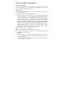
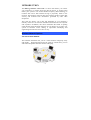
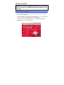
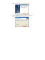
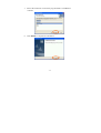
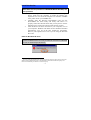
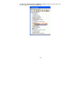
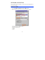
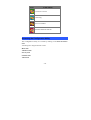
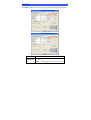
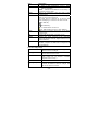
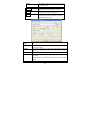
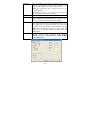
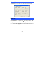
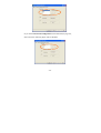
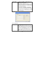
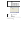
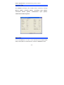
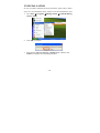
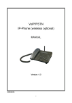
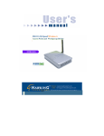
802.11g
Wireless LAN Card
User’s Manual
Doc. No.:120903-01
REGULATORY STATEMENTS
FCC Certification
The United States Federal Communication Commission (FCC) and the
Canadian Department of Communications have established certain rules
governing the use of electronic equipment.
Part15, Class B
This device complies with Part 15 of FCC rules. Operation is subject to the
following two conditions:
1) This device may not cause harmful interface, and
2) This device must accept any interface received, including interface that may
cause undesired operation. This equipment has been tested and found to
comply with the limits for a Class B digital device, pursuant to Part 15 of the
FCC Rules. These limits are designed to provide reasonable protection
against harmful interference in a residential installation. This equipment
generates, uses and can radiate radio frequency energy, and if not installed
and used in accordance with the instructions, may cause harmful interference
to radio communications. However, there is no guarantee that interference
will not occur in a particular installation. If this equipment does cause
harmful interference to radio or television reception, which can be
determined by turning off and on, the user is encouraged to try to correct the
interference by one or more of the following measures:
◗Reorient or relocate the receiving antenna.
◗Increase the distance between the equipment and receiver.
◗ Connect the equipment into an outlet on a circuit different from that to
which the receiver is connected.
CAUTION:
1) To comply with FCC RF exposure compliance requirements, a separation
distance of at least 20 cm must be maintained between the antenna of this
device and all persons.
2)
This transmitter must not be co-located or operating in conjunction with
any other antenna or transmitter.
Table of Contents
INTRODUCTION...................................................................................... 1
WIRELESS NETWORK OPTIONS ................................................................. 1
The Peer-to-Peer Network............................................................ 1
The Access Point Network........................................................... 2
LED INDICATORS FOR WIRELESS CARDBUS CARD .................................. 3
Power Indicator: (Orange LED) ................................................... 3
Act Indicator: (Green LED) ......................................................... 3
INSTALLATION ....................................................................................... 4
INSTALL THE DRIVER & UTILITY .............................................................. 4
INSTALL THE DEVICE................................................................................. 7
Note for Windows 98 users:......................................................... 7
Note for Windows 2000 users:..................................................... 8
Note for Windows XP users:........................................................ 8
Verify Device Installation ............................................................ 9
NETWORK CONNECTION.................................................................. 11
IN WINDOWS 98/ME............................................................................... 11
IN WINDOWS 2000/XP............................................................................ 14
CONFIGURATION................................................................................. 17
THE NETWORK STATUS ICON.................................................................. 17
ACCESSING THE CONFIGURATION UTILITY ............................................. 18
MAIN TAB ............................................................................................... 19
ADVANCED TAB ..................................................................................... 24
PRIVACY TAB ......................................................................................... 24
STATISTICS TAB ...................................................................................... 28
ABOUT TAB ............................................................................................ 28
UNINSTALLATION ............................................................................... 30
INTRODUCTION
The 802.11g Wireless LAN Card is a device that allows you connect
your computer to a wireless local area network (LAN). A wireless LAN
allows your system to use wireless Radio Frequency (RF) technology to
transmit and receive data without having to physically attach to the
network. The Wireless protocols that come with this product ensure data
security and isolation from interference generated by other radio
frequencies.
This card also allows you to take full advantage of your computer’s
mobility with access to real-time information and online services anytime
and anywhere. In addition, this device eliminates the bother of pulling
cable through walls and under furniture. It even allows you to place your
system in locations where cabling is impossible. Modifying and
augmenting networks has never been so easy.
Wireless Network Options
The Peer-to-Peer Network
This network installation lets you set a small wireless workgroup easily
and quickly. Equipped with wireless PC Cards or wireless PCI, you can
share files and printers between each PC and laptop.
-1-
You can also use one computer as an Internet Server to connect to a wired
global network and share files and information with other computers via a
wireless LAN.
The Access Point Network
The network installation allows you to share files, printers, and Internet
access much more conveniently. With Wireless LAN Cards, you can
connect wireless LAN to a wired global network via an Access Point.
-2-
LED Indicators For Wireless CardBus Card
Power Indicator: (Orange LED)
This LED will illuminate when the driver is well-installed.
Act Indicator: (Green LED)
This LED flickers when transmitting/receiving wireless data.
-3-
INSTALLATION
Caution: Do not insert the Wireless LAN Card into your computer
until the procedures in “Install the Driver & Utility” has been
performed.
Install the Driver & Utility
3.
4.
Exit all Windows programs. Insert the CD-ROM into the CD-ROM
drive of your computer.
If the CD-ROM is not launched automatically, go to your CD-ROM
drive (e.g. drive D) and double-click on Setup.exe.
The main screen of the CD-ROM opens. Click Driver & Utility
Installation to start the installation.
-4-
5. When the Welcome screen appears, click Next to continue.
6. The Choose Destination Location screen will show you the default
destination chosen by the utility. Click Next to continue.
-5-
7. Follow the instruction to select the program folder. Click Next to
continue.
8. Click Finish to complete the installation
-6-
Install the device1
Note: Make sure the procedures in “Install the Driver & Utility” has
been performed.
1.
2.
3.
If you are using the Wireless PCI Card, before installing the
device, make sure the computer is turned off. Remove the
expansion slot cover from the computer. For Wireless CardBus
users, please locate your CardBus slot.
Carefully slide the Wireless PCI/CardBus Card into the
PCI/CardBus slot. Push evenly and slowly and ensure it is
properly seated. For Wireless PCI Card, you may have to use the
mounting screw to have the card screwed securely in place.
After the device has been connected to your computer, turn on
your computer. Windows will detect the new hardware and then
automatically copy all of the files needed for networking.
Recover your expansion slot cover if you are using the Wireless
PCI Card.
Note for Windows 98 users:
Before installation of the device, make sure you have your operating
system CD-ROM at hand. You may be asked to insert the OS CD-ROM
in order to download specific drivers.
1
If you are using the Wireless PCI Card, the product descriptions shown on the screen will
differ from the illustrations shown in this document. Please discard the discrepancy and
follow the installation procedures to continue anyway.
-7-
Note for Windows 2000 users:
During the installation, when the “Digital Signature Not Found”
screen appears, click “Yes” to continue.
Note for Windows XP users:
1. Select Install the software automatically (Recommended) and click
Next.
-8-
3. Click Continue Anyway.
4. Click Finish to complete the installation.
Verify Device Installation
To verify that the device has been properly installed in your computer and
is enabled, go to Start ! Settings ! Control Panel ! System (!
Hardware) ! Device Manager. Expand the Network adapters item. If
-9-
the 802.11g Wireless PCI/CardBus PC Card is listed, it means that your
device is properly installed and enabled.
- 10 -
NETWORK CONNECTION
Once the driver has been installed, you will need to make adjustments to
your network settings.
In Windows 98/ME
1.
2.
Go to Start ! Settings ! Control Panel ! Network.
Make sure that you have all the following components installed.
" 802.11g Wireless PCI / CardBus PC Card
" IPX/SPX-compatible Protocol
" NetBEUI
" TCP/IP
- 11 -
If any components are missing, click on the Add button to install them.
All of the protocols and clients required (listed above) are provided by
Microsoft.
3. Next, highlight the specific network component you need, click Add.
4. Highlight Microsoft, and then double click on the item you want to
add. Click OK.
After returning to the Network screen, you can make your computer is
visible on the network by enabling the File and Print Sharing.
5. Click the Identification tab. Enter a name that is unique on the
network. Type the name of your workgroup, which should be the
same name used by all of the other PCs on the network.
- 12 -
6. Click the Access Control tab. Make sure that “Share-level access
control” is selected. If connecting to a Netware server, share level
can be set to “User-level access control.”
- 13 -
7. When finished, restart your computer to activate the new device.
8. Once the computer has been rebooted, a Logon window will appear
and will require you to enter a username and password. Enter a
username and password and click OK. Do not click the Cancel
button, or you won’t be able to log onto the network.
9. Double-click the Network Neighborhood icon on the windows
desktop, and you should see the names of the other PCs on the
network.
In Windows 2000/XP
1. (In Windows 2000)
Go to Start! Settings ! Control Panel ! Network and Dial-up
Connections ! Local Area Connection ! Properties.
(In Windows XP)
Go to Start ! Control Panel ! Network Connections ! Wireless
Network Connection Enabled 802.11g Wireless PCI/CardBus PC
Card ! Properties.
- 14 -
2. Make sure that you have all the following components installed.
" Client for Microsoft Networks
" NWLink NetBIOS
" NWLink IPX/SPX/NetBIOS Compatible Transport Protocol
" Internet Protocol (TCP/IP)
If any components are missing, click on the Install… button to select
the Client/Service/Protocol required.
3. After selecting the component you need, click Add… to install.
- 15 -
4. Select the network protocol you wish to add and click OK. This will
return you to the Local Area Connections Properties window.
5. To allow your computer to be visible on the network, make sure you
have checked off the File and Printer Sharing for Microsoft
Networks.
6. When finished, you must restart your computer to complete the
installation.
- 16 -
CONFIGURATION
After successful installation of the Wireless LAN Card’s driver, a
Network Status icon will display in the task bar. You will be able to
access the Configuration Utility through the Network Status icon.
If the icon doesn’t appear automatically, go to Start ! Programs !
802.11g WLAN ! 802.11g WLAN Utility, it will appear in the task bar.
The Network Status Icon
The Network Status Icon will display on the task bar of your desktop and
show the current network connection status of your system.
- 17 -
Icon
Link Status
Connected to network
Connecting
Driver not loaded
Disconnected from network
Accessing the Configuration Utility
The Configuration Utility is accessed by clicking on the Network Status
Icon.
All settings are categorized into 5 Tabs:
Main Tab
Advanced Tab
Privacy Tab
Statistics Tab
About Tab
- 18 -
Main Tab
The Main tab displays the current status of the Wireless Network Adapter.
Item
Description
External
To Enable or Disable the manufacturer’s configuration
Configuration
utility:
Enable : Check this item to use Windows XP build-in
- 19 -
Item
Status
SSID
Description
utility or other manufacturers’, such as Funk,
Odyssey client utility.
Disable :Left this item unchecked to use the utility we
provide.XP’s built-in utility
Displays the information about the status of the
communication.
The SSID is the unique name shared among all
points in your wireless network.
The name must be identical for all devices and
points attempting to connect to the same network.
No WEP key
With WEP key
For TI-Based WLAN devices
Mode
Ch
Signal
BBS ID
For TI-Based WLAN devices with WEP key
Displays the type of Basic Service Set, Access Point
or Peer to Peer.
Displays the channel that is currently in use.
Displays the signal strength of the connection
between the Wireless Network Adapter and the Access
Point it connects to.
A set of wireless stations is referred to as a Basic Service
Set (BSS). Computers in a BSS must be configured with
the same BSS ID.
Current Configuration
Pref. SSID
It shows the current SSID setting of the
Wireless Network Adapter.
BSS Type
Displays the type of Basic Service Set,
Access Point or Peer to Peer.
Channel
Shows the selected channel that is currently
used. (There are 14 channels available,
depends on the country.)
Tx Rate
Shows the current transfer rate.
Signal Quality
Displays the signal strength of the connection
between the Wireless Network Adapter and
the Access Point it connects.
- 20 -
BSSID
the BSSID of the Access Point to which the
card is associated
Connect
Highlight one of the device from the list area
and press the Connect button to access it.
There will be three tabs for you to modify, see
the detailed information on page 21.
Searches for all available networks. Clicking
on the button, the device will start to rescan
and list all available sites.
Modify
Rescan
Preferred
SSID
BSS Type
Tx Rate
Channel
Power Mode
IBSS
Type in the SSID name of the device you want to connect.
You can select Peer-to-Peer, Access Point or Auto Mode of the
device you to connect.
You can select the data rate or set to auto mode from the pull-down
menu.
Select the channel depends on your country.
No Power Save:Select this function , the adapter will be in full
active mode.
Max Power Save:Select this function, the power save mode will be
enabled.
The 802.11g standard includes a protection mechanism to
- 21 -
protection
4x Config
Mode
Profile
Tx Power Level
ensure mixed 802.11b and 802.11g operation. If there is no
such kind of mechanism exists, the two kinds of standards may
mutually interfere and decrease network’s performance.
NONE:if you select this item , then there will be no any
protection provided.
CTS only : Used only in the co-existing environment of
802.11b and 802.11g protection mechanism.
Select to disable or enable the TI-Based 4x function.
You can select IEEE 802.11b(B-Only), 802.11b +(B-Plus) ,
802.11g (G-Only)standard or B&G Mode (If you choose this option
the device will automatically convert the suitable standard ).
Enter the profile name and click the Save button to save
your configuration, To open the profiles you saved, select
the profile from the pull-down menu and then click the
Load button. To delete the profiles you saved, select the
profile from the pull-down menu and then click the
Delete button.
Transmit power level, includes Low Power,
Medium-Low Power, Medium Power, Medium-High
Power, High Power
- 22 -
Fragment Threshold
RTS Threshold
Preamble
Authentication
Retry limits
Antennas
802.11g version
To fragment MSDU or MMPDU into small sizes of
frames for increasing the reliability of frame (The
maximum value of 4096 means no fragmentation is
needed) transmission. The performance will be
decreased as well, thus a noisy environment is
recommended.
This value should remain at its default setting of
4096. Should you encounter inconsistent data
flow, only minor modifications of this value are
recommended.
A preamble is a signal used in wireless environment
to synchronize the transmitting timing including
Synchronization and Start frame delimiter. (Note: If
you want to change the Preamble type into Long or
Short, please check the setting of AP.)
The authentication type defines configuration
options for the sharing of wireless networks to
verify identity and access privileges of roaming
wireless network cards.
You may choose between Open System, Shared
Key, and Auto Switch.
Open System: If the Access Point is using "Open
System" authentication, then the wireless adapter
will need to be set to the same authentication type.
Shared Key: Shared Key is when both the sender
and the recipient share a secret key.
Auto Switch: Select Auto Switch for the adapter to
select the Authentication type automatically
depending on the Access Point Authentication type.
You can set the number of retries if no
acknowledgement appears from the receiving
station.
To set the type of the antenna
Tx Antenna:Antenna2 (Use the factory default)
RX Antenna:Both (Use the factory default)
This section is enabled only with G-Only
Mode
- 23 -
Advanced Tab
The Advanced tab displays the current status of the Wireless Network
Adapter.
Privacy Tab
Use the Privacy Tab to configure your WEP and CCX settings. WEP
(Wired Equivalent Privacy) and CCX(Cisco Compatible Extension)
encryption can be used to ensure the security of your wireless network.
If you left External Configuration unchecked in the Main tab(see page 9),
functions in the following figure will be enabled.
- 24 -
If you checked External Configuration in the Main tab(see page 10),
functions in the following figure will be disabled.
- 25 -
Privacy Mode
Configure your NONE 、WEP or CCX settings:
NONE:No security defined.
WEP (Wired Equivalent Privacy) is a data
security mechanism based on a 40 Bit/128 Bit/256
Bit shared key algorithm. Press the Select button to
change WEP configuration. A new dialog window
will be opened(see page 26)
CCX ( Cisco Compatible Extension ) . It
provides user-based, centralized authentication, as
well as per-user wired equivalent privacy (WEP)
session keys. Press the Select button to change
CCX configuration. A new dialog window will be
opened. (see page 27)
WEP Configuration
Encryption 1-4
To configure your WEP settings. WEP (Wired
Equivalent Privacy) encryption can be used to
ensure the security of your wireless network. Select
one Key and Key Size then fill in the appropriate
value/phrase in Encryption field. Note: You must
use the same Key and Encryption settings for the
both sides of the wireless network to connect
KEY1 ~ KEY 4:You can specify up to 4 different
keys to decrypt wireless data. Select the Default
- 26 -
Key size
key setting from the radio button.
Encryption:This setting is the configuration key
used in accessing the wireless network via WEP
encryption.
A key of 10 hexadecimal characters (0-9, A-F) is
required if a 64-bit Key Length was selected.
A key of 26 hexadecimal characters (0-9, A-F) is
required if a 128-bit Key Length was selected.
A key of 58 hexadecimal characters (0-9, A-F) is
required if a 256-bit Key Length was selected.
40 Bit, 128 Bit or 256 Bit.
CCX Configuration
Network Security None – Choosing it will enable the WEP Select
Type
button. As described in Page 26.
LEAP – Choosing it will enable the LEAP
security.
External – Select this item to use the external CCX
configuration utility.
LEAP User
Network administers have been taking advantage of the simplified user and
security administration that LEAP provides.
Before the security authentication is started, you should enter the user
- 27 -
name and password or the authentication process will fail.
Statistics Tab
The Statistics Tab displays the available statistic information including
Receive packets, Transmit packets, Association reject packets,
Association
timeout
packets,
Authentication
reject
packets,
Authentication timeout packets.
About Tab
Click on the About tab to view basic version information about the OS Version,
Utility Version, Driver Version, Firmware Version and EEPROM Version.
- 28 -
- 29 -
UNINSTALLATION
In case you need to uninstall the Utility and driver, please refer to below
steps. (As you uninstall the utility, the driver will be uninstalled as well.)
1. Go to Start ! Programs ! 802.11g WLAN ! Uninstall 802.11g
WLAN Utility.
2. Click OK to continue.
3. Select Yes, I want to restart my computer now, and then click
Finish to complete the uninstalled procedure.
- 30 -
- 31 -