1
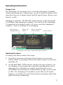
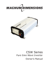
TC10
Owner’s Manual
Xantrex
Truecharge 10
Battery Charger
TM
2
Table of Contents
Introduction
Truecharge 10 Features
Theory of Operation
Important Safety Instructions
Permanent Installation
Battery Charging Safety
Grounding and AC Power Cord Connection Instructions
Operating Instructions
Care and Maintenance
Troubleshooting
Warranty Terms
Specifications
5
5
7
10
13
15
16
17
19
20
21
25
3
Xantrex Truecharge 10 Battery Charger © November 2002
Xantrex International. All rights reserved.
Truecharge is a registered trademark of Xantrex International.
Xantrex is a registered trademark of Xantrex International.
Disclaimer
UNLESS SPECIFICALLY AGREED TO IN WRITING, XANTREX TECHNOLOGY INC. (“XANTREX”)
(a) MAKES NO WARRANTY AS TO THE ACCURACY, SUFFICIENCY
OR SUITABILITY OF ANY TECHNICAL OR OTHER INFORMATION
PROVIDED IN ITS MANUALS OR OTHER DOCUMENTATION.
(b) ASSUMES NO RESPONSIBILITY OR LIABILITY FOR LOSS OR
DAMAGE, WHETHER DIRECT, INDIRECT, CONSEQUENTIAL OR
INCIDENTAL, WHICH MIGHT ARISE OUT OF THE USE OF SUCH
INFORMATION. THE USE OF ANY SUCH INFORMATION WILL BE
ENTIRELY AT THE USER’S RISK.
Date and Revision
November 2002, Revision 3
Part Number
445-0071-01-01 rev. 3
Contact Information
Web: www.xantrex.com
Email: [email protected]
Phone: 1 800 670 0707 (toll free)
1 604 422 2777 (direct)
Fax:
1 604 420 2145
4
Introduction
Your Xantrex Truecharge 10 is an advanced battery charger designed
specifically for today’s high performance deep-cycle lead-acid batteries.
It provides charging performance that simple marine and automotive
chargers are unable to provide.
The Truecharge 10 is designed to recharge 12 volt lead-acid batteries
with capacities from 25 amp hours to 200 amp hours. If you wish to
charge batteries with capacities greater than 200 amp hours, Xantrex’s
Truecharge 20 or Truecharge 40 chargers will be better choices.
To get the full benefit of the Truecharge 10’s capabilities, please read
and follow the instructions in this manual. This manual covers both the
TC10 115 VAC model and the international TC10i 230 VAC model.
TC10i input specifications are shown in parentheses. Pay special
attention to the Important Safety Instructions in this manual and to the
CAUTION and WARNING statements in this manual and on the
Truecharge 10.
Truecharge 10 Features
The Truecharge 10 is a true “smart charger” that automatically provides
the correct charge cycle for modern sealed (“gel”) or flooded (“wet”)
lead-acid batteries.
Microprocessor Controlled Three-Step Charging
Experts and battery manufacturers recommend that lead-acid batteries be
charged with a three-step charge cycle to provide a fast, complete charge.
The microprocessor in the Truecharge 10 precisely regulates the voltage
and current delivered to the battery, accurately charging without risk of
overcharging and battery damage.
Proprietary software algorithms compensate for a variety of conditions
which “fool” less sophisticated chargers into delivering an improper
charge.
Truecharge 10 10-Amp Continuous Rating
The Truecharge 10 will deliver its rated 10 ampere charging current for
most of the charging cycle. The charger only reduces the charging
current below this continuous rating level when the battery is
approaching full charge. Many other chargers only deliver their rated
5
charging current for a short initial part of the charge cycle. Charging
current decreases rapidly (“tapers off”) as the battery charges.
Because it delivers rated current over most of the charge cycle, your
Truecharge 10 will charge your batteries faster than many other chargers
rated at 20 amperes or more.
Wide Voltage Range Operation
Now you can give your battery a top-quality charge even when your AC
power isn’t top quality. The Truecharge 10 precisely maintains the
correct charging voltage for your battery when the AC line voltage drops
as low as 90 VAC, or rises as high as 135 VAC (200 to 260 VAC for the
international 230 VAC model). A surge protector in the Truecharge 10
protects it, and your 12-volt circuits, from surges and spikes on the AC
power line.
Selector Switch for Battery Type
The Truecharge 10 has a selector switch that allows you to set the
charger for the charging characteristics of the new sealed lead-acid “gel”
batteries, or for the charging characteristics of conventional flooded
batteries. By setting the switch correctly before you begin charging your
battery, you will be ensuring that it receives the best possible charge.
Extensive Protection Features
The Truecharge 10 will not begin delivering current until it detects that it
has been properly connected to a battery. You will have fewer worries
about accidental sparks as you make your connections to the battery. The
Truecharge 10 will not deliver current if it detects a reverse polarity
connection, a short circuit, or connection to a battery with incorrect
voltage. The Truecharge 10 will also shut down if it becomes overheated
because of inadequate ventilation.
Isolated Design
The DC battery charging circuits of the Truecharge 10 are electrically
isolated by a transformer from the AC power source circuits. This
improves your personal safety and ensures that there will be no
electrolysis problems when charging batteries on a boat.
6
Theory of Operation
High Frequency Power Converter
The Truecharge 10 uses modern high frequency switching power circuits
to convert the alternating current from the utility line to the low voltage
direct current required to charge the battery. The circuits are similar to
those used in power supplies for computers and other modern electronic
equipment.
The alternating current from the utility line is first rectified by diodes to
produce a high voltage direct current.
This direct current is switched at a very high frequency (approximately
75 kHz) to produce pulses of current which are stepped down to a lower
voltage by a small high frequency transformer. The low voltage pulses of
current from the secondary side of the transformer are rectified and
smoothed to create a continuous direct current which is sent to the
battery.
The power switching is performed by power MOSFET transistors. These
transistors also control the charging current and voltage through a
process called pulse width modulation (PWM). The average value of the
voltage or current is controlled by varying the lengths of the pulses of
current. Shorter duration pulses result in lower voltage and current while
longer duration pulses result in higher voltage or current.
The advanced power conversion technology in the Truecharge 10 gives
you several benefits:
• A charger that is smaller and lighter than most other chargers
with similar capabilities. The Truecharge 10 is easy to carry with
you and can be stored or installed in small compartments.
• A totally silent charger. There is none of the “hum” or “buzz”
commonly associated with chargers based on older technology.
• Non-pulsing charging current. While the Truecharge 10 uses
current pulses internally, the output current is filtered so that it is
very smooth. This is the ideal current for charging lead-acid
batteries. Many other chargers produce a pulsating charging
current that does not recharge the battery to its maximum
potential.
7
Three-Step Charging Process
Modern lead-acid batteries will last longer and charge faster if they are
charged in a particular sequence known as a three-step charge. The
Truecharge 10 implements the three-step charging process.
In the first step, known as the bulk charge, the Truecharge 10 delivers its
rated current (10 A) until the battery voltage approaches its gassing
voltage—typically around 14.4 volts. The bulk charge step restores about
75% of the battery's charge.
The gassing voltage is the voltage at which the electrolyte in the battery
begins to break down into hydrogen and oxygen gases. Under normal
circumstances, a battery should not be charged at a voltage above its
gassing voltage since this will cause the battery to lose electrolyte and
dry out over time. Therefore the Truecharge 10 transfers to the next step,
known as the absorption charge.
During the absorption charge, the charging voltage is held constant near
the gassing voltage and the charging current is steadily decreased. When
the charging current has decreased to approximately one ampere, the
battery is fully charged. At this point, the Truecharge 10 transfers to its
final step, known as the float charge.
The float charge is a maintenance mode in which the Truecharge 10
output voltage is reduced to a lower level, typically about 13.5 volts, to
maintain the battery's charge without losing electrolyte through gassing.
Unlike many other chargers, the Truecharge 10 can be left connected to
your battery indefinitely without risk of overcharging.
The voltage levels mentioned in the paragraphs above are dependent on
the type of battery (sealed vs. flooded) and on the temperature of the
battery. The Truecharge 10 is equipped with selector switches to allow
you to set it for your battery type and temperature.
Charger Operating Sequence
The microprocessor in the Truecharge 10 is constantly checking to
ensure that the charger is working properly.
Once AC power is connected to the Truecharge 10, the microprocessor
begins by checking whether a battery is connected properly to the
charger. The Truecharge 10 will only start charging if the following
8
conditions are met:
•
A battery is connected
•
The battery is connected with proper polarity
•
The battery voltage is between 5 volts and 13 volts
The Truecharge 10 will not act as a battery eliminator or power supply. It
must be connected to a battery to operate.
Once the Truecharge 10 detects proper connection to a battery, it begins
the three-step charging cycle. The Truecharge 10 will stop charging if it
detects the following conditions:
• Battery voltage less than 10 volts or greater than the gassing voltage
•
Internal charger temperature greater than 70 °C
The Truecharge 10 will automatically start charging again if it detects
that the battery voltage or charger temperature have returned to safe levels.
The Truecharge 10 completes the absorption charge and goes to float
mode when one of the following two conditions are met:
• Charger output current has dropped below one ampere (flooded
type batteries remain at absorption voltage for an additional hour
after current has dropped to one ampere)
• The charger has been in absorption charge mode for more than
5 hours.
This “time out” feature protects against situations where a load
connected to the battery prevents the charger current from dropping
below one ampere.
The Truecharge 10 will leave float mode and start another three-step
charging cycle under any one of the following conditions:
•
Battery voltage drops below 12.5 volts for more than 15 minutes
•
21 days have passed since the last charging cycle occurred
•
•
The battery has been disconnected for more than 30 seconds and is
then reconnected
AC power has been disconnected for more than 30 seconds.
9
The first two conditions ensure that the Truecharge 10 keeps your battery
“topped up” if it is left permanently connected. The last two conditions
ensure that the Truecharge 10 starts in a predictable fashion after you
disconnect the battery or the AC power.
WARNING! To reduce the risk of sparking and damage to your
Truecharge 10, always disconnect AC power from your Truecharge 10
before connecting or disconnecting the battery or batteries.
Important Safety Instructions
SAVE THESE INSTRUCTIONS. This manual contains important safety
and operating instructions for the Truecharge 10 battery charger.
•
Do not expose charger to rain, snow, or spray.
•
Use of attachments not recommended or sold by the battery charger
manufacturer may result in a risk of fire, electric shock, or injury to
persons.
•
To reduce risk of damage to electric plug and cord, pull by plug
rather than cord when disconnecting charger.
•
An extension cord should not be used unless absolutely necessary.
Use of improper extension cord could result in a risk of fire and
electric shock. If an extension cord must be used, make sure:
a) That pins on plug of extension cord are the same number, size
and shape as those of plug on charger.
b) That extension cord is properly wired and in good electrical
condition, and
c) That wire size is 18 AWG (0.8 mm2) or larger and cord is less
than 100 feet (30 m) long.
•
Do not operate charger with damaged cord or plug. Replace the cord
or plug immediately.
•
Do not operate the charger if it has received a sharp blow, been
dropped, or otherwise damaged in any way. If the charger is damaged, take it to a qualified service person.
•
Do not disassemble the charger. Take it to a qualified service person
when service or repair is required. Incorrect reassembly may result in
a risk of electrical shock or fire.
•
To reduce risk of electrical shock, disconnect power from the charger
10
before attempting any maintenance or cleaning.
WARNING! RISK OF EXPLOSIVE GASES.
WORKING IN THE VICINITY OF A LEAD-ACID BATTERY IS
DANGEROUS. BATTERIES GENERATE EXPLOSIVE GASES
DURING NORMAL BATTERY OPERATION. FOR THIS REASON IT IS OF UTMOST IMPORTANCE THAT YOU READ THIS
MANUAL AND FOLLOW THE INSTRUCTIONS EXACTLY.
•
To reduce the risk of battery explosion, follow these instructions and
those published by the battery manufacturer and the manufacturer of
the equipment in which the battery is installed.
•
Do not use this charger in a compartment in which ignition-protected
equipment is required.
Personal Precautions
•
Someone should be within range of your voice and close enough to
come to your aid when you work near a lead-acid battery.
•
Have plenty of fresh water and soap nearby in case battery acid
contacts skin, clothing, or eyes.
•
Wear complete eye protection and clothing protection. Avoid touching eyes while working near the battery.
•
If battery acid contacts skin or clothing, wash immediately with soap
and water. If acid enters eye, immediately flood eye with running
cold water for at least 20 minutes and get medical attention immediately.
•
NEVER smoke or allow a spark or flame in the vicinity of the
battery or engine.
•
Be extra cautious to reduce the risk of dropping a metal tool on the
battery. It might spark or short-circuit the battery or other electrical
part that may cause an explosion.
•
Before working with a lead-acid battery, remove personal metal
items such as rings, bracelets, necklaces, and watches. A lead-acid
battery produces a short-circuit current high enough to weld a ring or
the like to metal, causing a severe burn.
•
Use the charger for charging a LEAD-ACID battery only. Do not use
11
this battery charger to charge nickel-cadmium (Ni-Cd), nickel-metal
hydride (Ni-MH), lithium (Li) and dry cell batteries commonly used
with home appliances and electronic equipment. These batteries may
burst and cause injury to persons and damage to property. The
charger is not intended to supply power to an extra-low voltage
electrical system without a battery.
•
NEVER charge a frozen battery. Charging a battery when its temperature is below 32 °F (0 °C) is inefficient and ineffective. If
possible, warm the battery above 32 °F (0 °C) before charging.
Preparing to Charge
1) If it is necessary to remove the battery from its installed position to
charge, always remove the grounded terminal from the battery first.
Make sure all loads connected to the battery are off, so as not to
cause an arc.
2) Be sure the area around the battery is well ventilated while the
battery is being charged. Gas can be forcefully blown away by using
a piece of cardboard or other non-metallic material as a fan.
3) Clean the battery terminals and ensure that connections are secure.
Be careful to keep corrosion from coming in contact with eyes.
4) If you are charging a flooded battery, add distilled water to each cell
until battery acid reaches level specified by battery manufacturer.
This helps purge excessive gas from cells. Do not overfill. Never
allow battery acid to drip on charger when reading specific gravity or
filling battery. For a battery without cell caps, carefully follow the
manufacturer's recharging instructions.
5) Study and follow all battery manufacturer's specific precautions such
as removing or not removing cell caps while charging, and recommended rates of charge.
6) Ensure that battery voltage is 12 volts (nominal) by referring to
battery manufacturer's information, or manual for equipment in
which battery is installed. Do not attempt to charge a battery which
is not rated at 12 volts.
12
DC Connection Precautions
•
Connect DC output clips only after the AC cord is connected to the
electrical outlet and the charger indicator lights turn on. The charger
has an anti-sparking feature that only functions properly if the
charger is on.
•
Attach clips to battery posts and twist or rock back and forth several
times to make a good connection. This tends to keep the clips from
slipping off the terminals and helps to reduce risk of sparking.
•
Disconnect DC output clips only after the AC cord is disconnected
from the AC outlet.
Permanent Installation
Location
The Truecharge 10 should be installed in a location that meets the
following requirements:
1) Dry—Do not allow water or other fluids to drip or splash onto the
Truecharge 10. Do not mount the charger in an area subject to
splashing bilge water.
2) Cool—Ambient air temperature should be between 32 °F (0 °C) and
104 °F (40 °C)—the cooler the better.
3) Ventilated—Do not operate the charger in a closed-in area or restrict
ventilation in any way. Allow at least 4 inches (10 cm) of clearance
around the Truecharge 10 for air flow. If mounting in a compartment,
ventilate the compartment with louvers or cut-outs.
4) Safe—Do not install the Truecharge 10 in the same compartment as
batteries or in any compartment capable of storing flammable liquids
such as gasoline. Do not use the Truecharge 10 in an engine compartment or other location where ignition protected equipment is required.
5) Locate the charger as far away from the battery as the DC cables
permit.
6) Never place the charger on or directly above the battery being
charged. Gases from the battery will corrode and damage the charger.
7) Never allow battery acid to drip on the charger when reading specific
gravity or filling the battery.
8) Do not set a battery on top of the charger.
13
CAUTION! To reduce risk of fire, do not cover or obstruct the
ventilation openings. Do not install the Truecharge 10 in a zeroclearance compartment. Overheating may result.
WARNING: This equipment contains components that may produce
arcs or sparks. To prevent fire or explosion, do not install in
compartments containing batteries or flammable materials or in
locations that require ignition-protected equipment.
Temporary Mounting
The Truecharge 10 may be temporarily mounted during charging, using
the keyholes and holes provided. Mounting hardware should be
corrosion resistant #8 (4mm) screws.
The Truecharge 10 may be mounted on a flat, horizontal or vertical
surface. If mounting on a vertical surface such as a wall, the orientation
should be horizontal, with the keyholes at the top.
14
Battery Charging Safety
Charging a battery when it is installed in an engine compartment
To reduce the risk of a spark near the battery:
1) Position AC and DC cords to reduce risk of damage by access doors,
hood, or moving engine parts.
2) Stay clear of fan blades, belts, pulleys, and other parts that can cause
injury to persons.
3) Ensure that the compartment has been ventilated to remove flammable or explosive gasses such as battery gasses and fuel vapor. Fuel
vapor is heavier than air, so forced ventilation is required.
4) Check the polarity of the battery posts. The POSITIVE (POS, P, +)
battery post usually has a larger diameter than the NEGATIVE
(NEG, N, –) post.
5) Determine which post of the battery is grounded (connected) to
chassis or engine block. If negative post is grounded (as in most
systems) see the next item. If the positive post is grounded, see item 7.
6) For a negative grounded system, connect POSITIVE (RED) clip
from the battery charger to the POSITIVE (POS, P, +) ungrounded
post of the battery. Connect the NEGATIVE (BLACK) clip to the
engine block away from the battery. Do not connect the clip to the
carburetor, fuel lines, or sheet metal body parts. Connect to an
unpainted, clean, heavy-gauge metal part of the frame or engine
block.
7) For a positive grounded system, connect the NEGATIVE (BLACK)
clip from the battery charger to the ungrounded NEGATIVE (NEG,
N, –) post of the battery. Connect the POSITIVE (RED) clip to the
engine block away from the battery. Do not connect the clip to the
carburetor, fuel lines, or sheet metal body parts. Connect to an
unpainted, clean, heavy-gauge metal part of the frame or engine
block.
8) See the operating instructions for the length of charge information.
15
Charging a battery when it is installed outside the engine
compartment
To reduce the risk of a spark near the battery:
1) Check the polarity of the battery posts. The POSITIVE (POS, P, +)
battery post usually has a larger diameter than the NEGATIVE
(NEG, N, –) post.
2) Connect the charger to AC power. When the lights on the charger
begin to blink, connect the POSITIVE (RED) charger clip to the
positive (POS, P, +) post of the battery.
3) Connect the negative (BLACK) charger clip to the negative (NEG,
N, -) post of the battery.
4) As a precaution, do not face the battery when making the final connection.
5) When disconnecting, disconnect the AC power to the charger first,
then disconnect the negative (BLACK) charger clip while you are as
far away from the battery as possible. Disconnect the positive (RED)
charger clip last.
6) See the operating instructions for the length of charge information.
Grounding and AC Power Cord Connection Instructions
The charger should be grounded to reduce the risk of electrical shock.
The charger is supplied with an electric cord having an equipment
grounding conductor and a grounding plug. The plug must be plugged
into an outlet that is properly installed and grounded in accordance with
all local codes and ordinances.
Danger: Never alter the supplied AC cord or plug if it will not fit the
outlet. Have a proper outlet installed by a qualified electrician. Improper
connection can result in risk of an electric shock.
16
Operating Instructions
Charge Cycle
The Truecharge 10 can charge all 12 volt lead-acid batteries including
sealed, maintenance-free, and gel types. It is best suited for batteries with
capacities between 25 ampere hours and 200 ampere hours. (battery sizes
from U1 to 4D).
Charging is automatic. The READY status indicator on the Truecharge
10 will light when charging is complete. You can leave the Truecharge
10 connected to the batteries and to AC power even after charging is
complete—there is no danger of overcharging.
Battery Ready/
Charging Indicators
Battery Type
Switch
Battery Temperature
Output Ammeter
Selector Switch
Truecharge 10 Top Label—Switch and LED Descriptions
Operating Procedure
To charge your battery follow these steps:
1) If possible, disconnect all loads from the battery, by removing
battery cables, by opening a battery disconnect switch, or by switching loads off.
2) Set the BATTERY TYPE selector switch to the type of battery you
are charging. If your battery has removable caps that allow you to
add water, it is a flooded type, and the switch should be set to
FLOODED. If your battery is sealed and has no caps, set the switch
to GEL. The Truecharge 10 should be set for GEL for all sealed
batteries, even if they use starved-electrolyte technology rather than
gelled electrolyte technology.
17
3) Set the BATTERY TEMPERATURE selector switch for the temperature of your battery. If your battery temperature is below 50 °F,
(10 °C), set the switch to COLD. If your battery temperature is
between 50 °F (10 °C) and 80 °F (27 °C), set the switch to HOT.
4) Attach the supplied AC power cord and connect the Truecharge 10 to
AC power (90 VAC to 130 VAC 50/60 Hz. The indicator lights on
the Truecharge 10 will begin blinking in sequence. The Truecharge
10 may take up to one minute to begin charging.
IMPORTANT: Connect the Truecharge 10 to AC power before connecting the battery. This will prevent arcing when connecting the battery.
5) Ventilate the area around the battery thoroughly. Connect the
Truecharge 10 to the battery. Ensure proper polarity: RED clip to the
positive (+) terminal and the BLACK clip to the negative (–) terminal. The Truecharge 10 is protected against reverse connection. It
will not begin charging if the battery is incorrectly connected.
6) The Truecharge 10 will now start charging the battery, as indicated
by the yellow CHARGING indicator lighting.
7) During charging, the charging current will be indicated by the
CHARGE CURRENT lights. When charging a discharged battery,
the 10 A indicator will be on for most of the charging cycle. Near the
end of the cycle, the charging current will decrease and the 8 A, 6 A,
and 2 A indicators will come on in sequence.
8) When the green READY indicator lights, the battery is fully charged
and ready for use. While the READY indicator is on, the Truecharge
10 is in its float charge mode, and will maintain the battery’s charge
if it is not disconnected.
9) IMPORTANT: To disconnect the Truecharge 10 from the battery,
first disconnect the AC power, then disconnect the battery clips. This
will prevent arcing. Also be sure to ventilate the area around the
battery thoroughly before disconnecting.
18
Charging Times
Charging time will depend on the capacity of your battery and on how
deeply it is discharged. The following equation gives an approximate
charging time:
Charging time = CAP × DOD
850
where:
Charging Time = Battery recharge time in hours
CAP = Battery capacity in ampere hours
DOD = Battery depth of discharge in % (A fully discharged battery
has 100% DOD)
Example:
The battery is a Group 27 size with a rated capacity of 80 ampere-hours.
It is 80% discharged (i.e. DOD = 80). Charging time with a Truecharge
10 will be:
80 × 80 = 7.5 hours
850
Care and Maintenance
Your Truecharge 10 contains solid-state electronic components that
require no maintenance. The best care you can give your Truecharge 10
is to protect it from contact with liquids, spray, or fumes that may cause
corrosion. Clean the case and cords with a damp cloth if you suspect
contact with battery fluid, salt water, gasoline or oil, or other corrosive
material. Corrosion on the clips may be removed with a solution of water
and baking soda.
CAUTION! RISK OF ELECTRICAL SHOCK. The Truecharge 10
contains no user-serviceable components. Do not open the unit or
attempt to service the unit. Contact your dealer or the manufacturer for
service information.
19
Troubleshooting
Problem
Possible Cause
Solution
Indicator lights are all
off when charger is
connected to an AC
receptacle.
No power at AC
receptacle.
Defective cord.
Open fuse in charger.
Indicator lights
continue to scroll
when the charger is
connected to a battery
and AC
Check polarity and quality of battery
Charger does not detect
battery for one of following connection.
reasons:
If leads are damaged or internal fuse
- poor or no connection
- reverse polarity connection open, have charger serviced by qualified
- damaged leads
person.
- open fuse in charger.
or “Charging”
indicator does not turn
Battery voltage too low.
on continuously
or “Ready” indicator
blinks continuously.
“Charging” light blinks
but does not come on
steadily. Other
indicator lights are off.
Ensure that power is available at
receptacle.
Replace wiring.
Have charger serviced by qualified
person.
Check battery voltage rating. Do not
attempt to charge a battery rated 6 volts.
If battery is rated for 12 volts, leave
connected for 8 hours to see if it will
recover. If battery doesn’t start charging
after 8 hours, it is probably damaged and
will not accept a charge.
Battery voltage is too high.
Check battery. Do not charge a battery
rated at more than 12 volts nominal.
Battery is connected to
another charging source.
Disconnect or turn off other charging
source (e.g. an alternator).
“10A” indicator light
Charger has shut down due
blinks. Other indicator to internal overheating.
lights are off.
Allow charger to cool. Improve
ventilation or install in cooler location.
Charger appears to be
taking too long to
charge battery. Ready
indicator does not light
after 24 hours of
charging.
Use a higher capacity charger.
Battery capacity is greater
than 200 amp hours.
Load connected to battery is Disconnect load or switch load off.
draining charge current so
that battery does not
recharge.
Battery has a damaged cell.
20
Replace battery.
Warranty Terms
What does this warranty cover?
This Limited Warranty is provided by Xantrex Technology, Inc. ("Xantrex") and covers defects in
workmanship and materials in your Xantrex Truecharge 10. This warranty lasts for a Warranty
Period of 12 months from the date of purchase at point of sale to you, the original end user
customer.
This Limited Warranty is transferable to subsequent owners but only for the unexpired portion of
the Warranty Period.
What will Xantrex do?
Xantrex will, at its option, repair or replace the defective product free of charge, provided that you
notify Xantrex of the product defect within the Warranty Period, and provided that Xantrex through
inspection establishes the existence of such a defect and that it is covered by this Limited Warranty.
Xantrex will, at its option, use new and/or reconditioned parts in performing warranty repair and
building replacement products. Xantrex reserves the right to use parts or products of original or
improved design in the repair or replacement. If Xantrex repairs or replaces a product, its warranty
continues for the remaining portion of the original Warranty Period or 90 days from the date of the
return shipment to the customer, whichever is greater. All replaced products and all parts removed
from repaired products become the property of Xantrex.
Xantrex covers both parts and labor necessary to repair the product, and return shipment to the
customer via a Xantrex-selected non-expedited surface freight within the contiguous United States
and Canada. Alaska and Hawaii are excluded. Contact Xantrex Customer Service for details on
freight policy for return shipments outside of the contiguous United States and Canada.
How do you get service?
If your product requires troubleshooting or warranty service, contact your merchant. If you are
unable to contact your merchant, or the merchant is unable to provide service, contact Xantrex
directly at:
Phone: 1 800 670 0707 (toll free in North America) 1 604 422 2777 (direct)
Fax: 1 604 420 2145
Email: [email protected]
Direct returns may be performed according to the Xantrex Return Material Authorization Policy
described in your product manual. For some products, Xantrex maintains a network of regional
Authorized Service Centers. Call Xantrex or check our website to see if your product can be
repaired at one of these facilities.
In any warranty claim, dated proof of purchase must accompany the product and the product must
not have been disassembled or modified without prior written authorization by Xantrex.
Proof of purchase may be in any one of the following forms:
•
The dated purchase receipt from the original purchase of the product at point of sale to the end
user, or
•
The dated dealer invoice or purchase receipt showing original equipment manufacturer (OEM)
status, or
•
The dated invoice or purchase receipt showing the product exchanged under warranty
What does this warranty not cover?
This Limited Warranty does not cover normal wear and tear of the product or costs related to the
removal, installation, or troubleshooting of the customer's electrical systems. This warranty does not
apply to and Xantrex will not be responsible for any defect in or damage to:
a) the product if it has been misused, neglected, improperly installed, physically damaged or
21
b)
c)
d)
e)
altered, either internally or externally, or damaged from improper use or use in an unsuitable
environment;
the product if it has been subjected to fire, water, generalized corrosion, biological
infestations, or input voltage that creates operating conditions beyond the maximum or
minimum limits listed in the Xantrex product specifications including high input voltage from
generators and lightning strikes;
the product if repairs have been done to it other than by Xantrex or its authorized service
centers (hereafter "ASCs");
the product if it is used as a component part of a product expressly warranted by another
manufacturer;
the product if its original identification (trade-mark, serial number) markings have been
defaced, altered, or removed.
Disclaimer
Product
THIS LIMITED WARRANTY IS THE SOLE AND EXCLUSIVE WARRANTY PROVIDED BY
XANTREX IN CONNECTION WITH YOUR XANTREX PRODUCT AND IS, WHERE
PERMITTED BY LAW, IN LIEU OF ALL OTHER WARRANTIES, CONDITIONS,
GUARANTEES, REPRESENTATIONS, OBLIGATIONS AND LIABILITIES, EXPRESS OR
IMPLIED, STATUTORY OR OTHERWISE IN CONNECTION WITH THE PRODUCT,
HOWEVER ARISING (WHETHER BY CONTRACT, TORT, NEGLIGENCE, PRINCIPLES OF
MANUFACTURER'S LIABILITY, OPERATION OF LAW, CONDUCT, STATEMENT OR
OTHERWISE), INCLUDING WITHOUT RESTRICTION ANY IMPLIED WARRANTY OR
CONDITION OF QUALITY, MERCHANTABILITY OR FITNESS FOR A PARTICULAR
PURPOSE. ANY IMPLIED WARRANTY OF MERCHANTABILITY OR FITNESS FOR A
PARTICULAR PURPOSE TO THE EXTENT REQUIRED UNDER APPLICABLE LAW TO
APPLY TO THE PRODUCT SHALL BE LIMITED IN DURATION TO THE PERIOD
STIPULATED UNDER THIS LIMITED WARRANTY.
IN NO EVENT WILL XANTREX BE LIABLE FOR ANY SPECIAL, DIRECT, INDIRECT,
INCIDENTAL OR CONSEQUENTIAL DAMAGES, LOSSES, COSTS OR EXPENSES HOWEVER ARISING WHETHER IN CONTRACT OR TORT INCLUDING WITHOUT RESTRICTION ANY ECONOMIC LOSSES OF ANY KIND, ANY LOSS OR DAMAGE TO PROPERTY,
ANY PERSONAL INJURY, ANY DAMAGE OR INJURY ARISING FROM OR AS A RESULT
OF MISUSE OR ABUSE, OR THE INCORRECT INSTALLATION, INTEGRATION OR
OPERATION OF THE PRODUCT.
Exclusions
If this product is a consumer product, federal law does not allow an exclusion of implied warranties.
To the extent you are entitled to implied warranties under federal law, to the extent permitted by
applicable law they are limited to the duration of this Limited Warranty. Some states and provinces
do not allow limitations or exclusions on implied warranties or on the duration of an implied
warranty or on the limitation or exclusion of incidental or consequential damages, so the above
limitation(s) or exclusion(s) may not apply to you. This Limited Warranty gives you specific legal
rights. You may have other rights which may vary from state to state or province to province.
Warning: Limitations On Use
Please refer to your product user manual for limitations on uses of the product. Specifically, please
note that the Xantrex Truecharge 10 is not intended for use in connection with life support systems
and Xantrex makes no warranty or representation in connection with any use of the product for such
purposes.
22
Return Material Authorization Policy
Before returning a product directly to Xantrex you must obtain a Return Material Authorization
(RMA) number and the correct factory "Ship To" address. Products must also be shipped prepaid.
Product shipments will be refused and returned at your expense if they are unauthorized, returned
without an RMA number clearly marked on the outside of the shipping box, if they are shipped
collect, or if they are shipped to the wrong location.
When you contact Xantrex to obtain service, please have your instruction manual ready for
reference and be prepared to supply:
•
The serial number of your product
•
Information about the installation and use of the unit
•
Information about the failure and/or reason for the return
•
A copy of your dated proof of purchase
Return Procedure
1.
Package the unit safely, preferably using the original box and packing materials. Please ensure
that your product is shipped fully insured in the original packaging or equivalent. This
warranty will not apply where the product is damaged due to improper packaging.
2.
Include the following:
•
The RMA number supplied by Xantrex Technology Inc clearly marked on the outside of the
box.
•
A return address where the unit can be shipped. Post office boxes are not acceptable.
•
A contact telephone number where you can be reached during work hours
•
A brief description of the problem
3.
Ship the unit prepaid to the address provided by your Xantrex customer service representative.
If you are returning a product from outside of the USA or Canada
In addition to the above, you MUST include return freight funds and are fully responsible for all
documents, duties, tariffs, and deposits.
If you are returning a product to a Xantrex Authorized Service Center (ASC)
A Xantrex return material authorization (RMA) number is not required. However, you must contact
the ASC prior to returning the product or presenting the unit to verify any return procedures that
may apply to that particular facility.
23
24
Specifications
Output current:
10 amps continuous duty
Output voltage
Charge:
Float:
14.2–14.4 VDC (depending on setting)
13.5–13.8 VDC (depending on setting)
Input voltage:
120 VAC nominal (90–135 VAC)
50/60 Hz
Efficiency:
85%
Weight:
3 lbs. / 1.4 kg
Dimensions (L x W x H): 9" x 6.5" x 2.75"
23 cm x 16.5 cm x 7 cm
Output Fuse:
15 A, 32 V, automotive blade type
IMPORTANT! Disconnect all power to charger, including batteries,
before replacing fuses.
Specifications subject to change without notice.
25
Xantrex Technology Inc.
Toll free 1 800 670 0707
Direct 1 604 422 2777
Fax 1 604 420 2145
[email protected]
www.xantrex.com
445-0071-01-01 Rev. 3
Printed in China