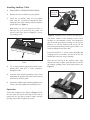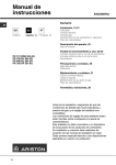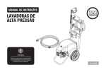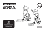
1
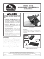
MODEL D3978
ACCU-SHARP® GRINDING JIG
INSTRUCTIONS
To reduce the risk of serious injury when using
this grinding jig, take the following precautions:
1. GRINDER OWNER'S MANUAL. Read
and understand the owner's manual for your
grinder and always follow all of the safety
precautions and instructions for your grinder.
2. EYE/FACE PROTECTION. Always wear
safety glasses or a face shield to protect yourself from flying material.
3. HAND PLACEMENT. Always keep your
hands and fingers away from the spinning
grinding wheel, and protect yourself from the
sharp edges of the tool.
4. SECURE CLAMPING. Make sure the tool is
securely clamped in the jig and that the table is
firmly locked in the proper position.
Introduction
The Model D3978 Accu-Sharp® Grinding Jig works
with the tool rest table of your grinder to properly position chisels and plane irons up to 2 3⁄4" wide, as shown
in Figure 1. The tool clamping jig uses a special
plastic rod and pads to slide the tool from side-to-side
across the auxiliary table and the grinding wheel.
Figure 1. Using the Accu-Sharp Jig to grind the bevel
of a flat chisel.
Inventory
After removing the contents of the shipping package,
lay them out and refer to Figure 2 to inventory the
components.
Tool
Clamping
Jig
Mounting
Screws
Auxiliary
Table
If you need help with your new grinding jig, call
Woodstock Tech Support at: (360) 734-3482.
Figure 2. Model D3978 inventory.
COPYRIGHT © NOVEMBER, 2008 BY WOODSTOCK INTERNATIONAL, INC.
#11386TS
WARNING: NO PORTION OF THIS MANUAL MAY BE REPRODUCED IN ANY SHAPE OR FORM WITHOUT
THE WRITTEN APPROVAL OF WOODSTOCK INTERNATIONAL, INC.
Printed in China
Installing Auxiliary Table
1. DISCONNECT GRINDER FROM POWER!
2. Remove the tool rest table from your grinder.
3. Center the jig auxiliary table over the grinder
table, then use a scratch awl through the three
mounting holes of the auxiliary table to mark the
grinder table (see Figure 3).
Note: Make sure that you position the tables so
that when the jig is mounted on the grinder, the
auxiliary table edge shown in Figure 3 is facing
the grinding wheel.
Mounting Holes
Auxilar
y Table
Edge F
aces Gr
inder
Figure 3. The mounting holes of the jig auxiliary
table.
4. Use a center punch to indent these marks on the
grinder table, then drill 7⁄32" holes completely
through the table.
Clamping
Screws &
Washers
90° Stop
Pins
Figure 4. Clamping screws, washers, and stop pins.
The plastic washers of the clamping screws can be
arranged to accommodate various tool thicknesses
and to provide good thread bearing for the screws.
However, be sure the bottom of the screws do not
protrude beyond the bottom of the jig more than 1 ⁄ 8" to
avoid scratching the auxiliary table.
If your tool width is 1 1 ⁄ 8" or less, remove the right-hand
clamping screw and washers and thread it into the
middle hole to provide secure clamping.
Place the tool and jig on the auxiliary table, align
and lock the table in place, then slide the tool across
the rotating grinding wheel with light pressure (see
Figure 5).
5. Insert the three included mounting screws from
underneath the grinder table, then loosely thread
them into the auxiliary table.
6. Square the auxiliary table with the grinding wheel
surface, then fully tighten the mounting screws.
Operation
Loosen the clamping screws shown in Figure 4, slide
the tool under the top bar and align its left side up
against the 90° stop pins to make it square with the
grinding wheel, then re-tighten the screws.
Figure 5. Plane iron clamped in the jig.