1
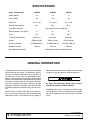
Rev. 3/09/2010 MAN0101 STR48S-2 STR60S-2 STR72S-2 Tested. Proven. Unbeatable. OPERATOR'S MANUAL Super Turf Renovator & Seedbox TO THE DEALER: Assembly and proper installation of this product is the responsibility of the Woods® dealer. Read manual instructions and safety rules. Make sure all items on the Dealer’s Pre-Delivery and Delivery Check Lists in the Operator’s Manual are completed before releasing equipment to the owner. The dealer must complete the online Product Registration form at the Woods Dealer Website which certifies that all Dealer Check List items have been completed. Please contact your dealer to complete this form. Dealers can register all Woods product at dealer.WoodsEquipment.com under Product Registration. Failure to register the product does not diminish customer’s warranty rights. TO THE OWNER: Read this manual before operating your Woods equipment. The information presented will prepare you to do a better and safer job. Keep this manual handy for ready reference. Require all operators to read this manual carefully and become acquainted with all adjustment and operating procedures before attempting to operate. Replacement manuals can be obtained from your dealer. To locate your nearest dealer, check the Dealer Locator at www.WoodsEquipment.com, or in the United States and Canada call 1-800-319-6637. The equipment you have purchased has been carefully engineered and manufactured to provide dependable and satisfactory use. Like all mechanical products, it will require cleaning and upkeep. Lubricate the unit as specified. Observe all safety information in this manual and safety decals on the equipment. For service, your authorized Woods dealer has trained mechanics, genuine Woods service parts, and the necessary tools and equipment to handle all your needs. Use only genuine Woods service parts. Substitute parts will void the warranty and may not meet standards required for safe and satisfactory operation. Record the model number and serial number of your equipment in the spaces provided: Model: _______________________________ Date of Purchase: _____________________ Serial Number: (see Safety Decal section for location) ____________________________________ Provide this information to your dealer to obtain correct repair parts. Throughout this manual, the term NOTICE is used to indicate that failure to observe can cause damage to equipment. The terms CAUTION, WARNING, and DANGER are used in conjunction with the Safety-Alert Symbol (a triangle with an exclamation mark) to indicate the degree of hazard for items of personal safety. 2 Introduction Gen’l (Rev. 3/5/2010) TABLE OF CONTENTS INTRODUCTION . . . . . . . . . . . . . . . . . . . . . . . . . . . . . . . . . . . . . . . . . . . . . . .2 SPECIFICATIONS. . . . . . . . . . . . . . . . . . . . . . . . . . . . . . . . . . . . . . . . . . . . . .4 GENERAL INFORMATION . . . . . . . . . . . . . . . . . . . . . . . . . . . . . . . . . . . . . . .4 SAFETY RULES . . . . . . . . . . . . . . . . . . . . . . . . . . . . . . . . . . . . . . . . . . . . . . .5 SAFETY DECALS . . . . . . . . . . . . . . . . . . . . . . . . . . . . . . . . . . . . . . . . . . . . . .7 OPERATION . . . . . . . . . . . . . . . . . . . . . . . . . . . . . . . . . . . . . . . . . . . . . . . . . .9 OWNER SERVICE . . . . . . . . . . . . . . . . . . . . . . . . . . . . . . . . . . . . . . . . . . . .14 ASSEMBLY INSTRUCTIONS . . . . . . . . . . . . . . . . . . . . . . . . . . . . . . . . . . . .15 PARTS INDEX . . . . . . . . . . . . . . . . . . . . . . . . . . . . . . . . . . . . . . . . . . . . . . . .17 BOLT TORQUE CHART . . . . . . . . . . . . . . . . . . . . . . . . . . . . . . . . . . . . . . . .24 BOLT SIZE CHART & ABBREVIATIONS . . . . . . . . . . . . . . . . . . . . . . . . . . .25 REPLACEMENT PARTS WARRANTY . . . . . . . . . . . . . . . . . . . . . . . . . . . . .26 PRODUCT WARRANTY . . . . . . . . . . . . . . . . . . . . . . . INSIDE BACK COVER ! LEA EL INSTRUCTIVO! Si no lee Ingles, pida ayuda a alguien que si lo lea para que le traduzca las medidas de seguridad. MAN0101 (Rev. 9/15/2006 Introduction 3 SPECIFICATIONS Super Turf Renovator STR48S STR60S STR72S Working Width 47" 59" 71" Overall Width 58" 70" 82" 1/2" x 1-3/4" 1/2" x 1-3/4" 1/2" x 1-3/4" Six 1" Six 1" Six 1" Roller Pins Bearing (Self-Aligning) Front Roller Positions Adjustable for Increased Agitation Roller Diameter: Front & Rear 8" 8" 8" Cat. I Cat. I Cat. I 65 HP Max. 65 HP Max. 65 HP Max. STR48: 565 lbs. STR60: 710 lbs. STR72: 855 lbs. Weight w/Seedbox STR48S: 820 lbs. STR60S: 920 lbs. STR72S: 1050 lbs. Seedbox Capacity 3 Bushel 4 Bushel 5 Bushel Hitch Tractor HP Requirement Weight Seed Distribution Method Metered gear with flow adjustment lever GENERAL INFORMATION The purpose of this manual is to assist you in operating and maintaining your Super Turf Renovator. Read it carefully. It furnishes information and instructions that will help you achieve years of dependable performance. These instructions have been compiled from extensive field experience and engineering data. Some information may be general in nature due to unknown and varying operating conditions. However, through experience and these instructions, you should be able to develop procedures suitable to your particular situation. The illustrations and data used in this manual were current at the time of printing but, due to possible inline production changes, your machine may vary slightly in 4 Introduction detail. We reserve the right to redesign and change the machines as may be necessary without notification. WARNING ■ Super Turf Renovator should never be operated with any safety shielding removed. Throughout this manual, references are made to right and left direction. These are determined by standing behind the equipment facing the direction of forward travel. (Rev 3/09/2010) MAN0101 (Rev. 9/15/2006) SAFETY RULES ATTENTION! BECOME ALERT! YOUR SAFETY IS INVOLVED! Safety is a primary concern in the design and manufacture of our products. Unfortunately, our efforts to provide safe equipment can be wiped out by an operator’s single careless act. In addition to the design and configuration of equipment, hazard control and accident prevention are dependent upon the awareness, concern, judgement, and proper training of personnel involved in the operation, transport, maintenance, and storage of equipment. It has been said, “The best safety device is an informed, careful operator.” We ask you to be that kind of operator. fastened. Falling off power unit can result in death from being run over or crushed. Keep foldable ROPS system in “locked up” position at all times. Make sure all safety decals are installed. Replace if damaged. (See Safety Decals section for location.) A minimum 20% of tractor and equipment weight must be on the tractor front wheels when attachments are in transport position. Without this weight, tractor could tip over, causing personal injury or death. The weight may be attained with a loader, front wheel weights, ballast in tires or front tractor weights. Weigh the tractor and equipment. Do not estimate. TRAINING OPERATION Safety instructions are important! Read all attachment and power unit manuals; follow all safety rules and safety decal information. (Replacement manuals and safety decals are available from your dealer. To locate your nearest dealer, check the Dealer Locator at www.WoodsEquipment.com, or in the United States and Canada call 1-800-3196637.) Failure to follow instructions or safety rules can result in serious injury or death. Keep bystanders away from equipment. If you do not understand any part of this manual and need assistance, see your dealer. Always comply with all state and local lighting and marking requirements. Know your controls and how to stop engine and attachment quickly in an emergency. Never allow riders on power unit or attachment. Operators must be instructed in and be capable of the safe operation of the equipment, its attachments, and all controls. Do not allow anyone to operate this equipment without proper instructions. Never allow children or untrained persons to operate equipment. PREPARATION Check that all hardware is properly installed. Always tighten to torque chart specifications unless instructed otherwise in this manual. Always wear relatively tight and belted clothing to avoid getting caught in moving parts. Wear sturdy, rough-soled work shoes and protective equipment for eyes, hair, hands, hearing, and head; and respirator or filter mask where appropriate. Make sure attachment is properly secured, adjusted, and in good operating condition. Power unit must be equipped with ROPS or ROPS cab and seat belt. Keep seat belt securely STR48-72 Safety Rules (Rev. 7/28/2005) Do not operate or transport equipment while under the influence of alcohol or drugs. Operate only in daylight or good artificial light. Keep hands, feet, hair, and clothing away from equipment while engine is running. Stay clear of all moving parts. Power unit must be equipped with ROPS or ROPS cab and seat belt. Keep seat belt securely fastened. Falling off power unit can result in death from being run over or crushed. Keep foldable ROPS system in “locked up” position at all times. Always sit in power unit seat when operating controls or starting engine. Securely fasten seat belt, place transmission in neutral, engage brake, and ensure all other controls are disengaged before starting power unit engine. Look down and to the rear and make sure area is clear before operating in reverse. Use extreme care when working close to fences, ditches, other obstructions, or on hillsides. Do not operate or transport on steep slopes. Do not stop, start, or change directions suddenly on slopes. Use extreme care and reduce ground speed on slopes and rough terrain. (Safety Rules continued on next page) Safety 5 SAFETY RULES ATTENTION! BECOME ALERT! YOUR SAFETY IS INVOLVED! (Safety Rules continued from previous page) Watch for hidden hazards on the terrain during operation. Stop power unit and equipment immediately upon striking an obstruction. Turn off engine, remove key, inspect, and repair any damage before resuming operation. MAINTENANCE Before dismounting power unit or performing any service or maintenance, follow these steps: disengage power to equipment, lower the 3-point hitch and all raised components to the ground, operate valve levers to release any hydraulic pressure, set parking brake, stop engine, remove key, and unfasten seat belt. NEVER GO UNDERNEATH EQUIPMENT. Never place any part of the body underneath equipment or between moveable parts even when the engine has been turned off. Hydraulic system leak-down, hydraulic system failures, mechanical failures, or movement of control levers can cause equipment to drop or rotate unexpectedly and cause severe injury or death. • Service work does not require going underneath. • Read Operator's Manual for service instructions or have service performed by a qualified dealer. 6 Safety Always wear relatively tight and belted clothing to avoid getting caught in moving parts. Wear sturdy, rough-soled work shoes and protective equipment for eyes, hair, hands, hearing, and head; and respirator or filter mask where appropriate. Make sure attachment is properly secured, adjusted, and in good operating condition. Keep all persons away from operator control area while performing adjustments, service, or maintenance. Tighten all bolts, nuts, and screws to torque chart specifications. Check that all cotter pins are installed securely to ensure equipment is in a safe condition before putting unit into service. Make sure all safety decals are installed. Replace if damaged. (See Safety Decals section for location.) STORAGE Block equipment securely for storage. Keep children and bystanders away from storage area. STR48-72 Safety Rules (Rev. 7/28/2005) SAFETY & INSTRUCTIONAL DECALS ATTENTION! BECOME ALERT! YOUR SAFETY IS INVOLVED! Replace Immediately If Damaged! MODEL NO. SERIAL NO. Woods Equipment Company Oregon, Illinois, U.S.A. 3 - Serial Number Plate 6 - PN 20106 Red Reflector 9 - PN 24611 Slow Moving Vehicle 4 - PN 15502 WARNING ROTATING COMPONENTS 5 - PN 18868 Do not operate without cover in place. Look and listen for rotation. Do not open cover until all components have stopped. SHIELD MISSING CONTACT WITH ROTATING PARTS CAN CAUSE SERIOUS INJURY. Do not operate. Put shield on. DANGER 15502--B 18868-B BE CAREFUL! Use a clean, damp cloth to clean safety decals. Avoid spraying too close to decals when using a pressure washer; high-pressure water can enter through very small scratches or under edges of decals causing them to peel or come off. Replacement safety decals can be ordered free from your Woods dealer. To locate your nearest dealer, check the Dealer Locator at www.WoodsEquipment.com, or in the United States and Canada call 1-800-319-6637. (Safety Decals continued on next page) MAN0101 (Rev.9/15/2006) Safety 7 SAFETY & INSTRUCTIONAL DECALS ATTENTION! BECOME ALERT! YOUR SAFETY IS INVOLVED! Replace Immediately If Damaged! (Safety Decals continued from previous page) WARNING FALLING OFF CAN RESULT IN BEING RUN OVER. Tractor must be equipped with ROPS (or ROPS CAB) and seat belt. Keep foldable ROPS systems in “locked up” position at all times. Buckle Up! Keep seat belt securely fastened. Allow no riders. RAISED IMPLEMENT CAN DROP AND CRUSH. Never go underneath raised implement which can drop from equipment or tractor 3-point hitch hydraulic leak down, hydraulic system failures, movement of control levers or mechanical linkage failures. Service work does not require going underneath implement. Read manual instructions. FALLING OFF OR GOING UNDERNEATH IMPLEMENT CAN RESULT IN SERIOUS INJURY OR DEATH. 55121--C 1 - PN 55121 7 - PN 1003751 2 - PN 55122 WARNING WARNING TO AVOID SERIOUS INJURY OR DEATH: Read Operator's Manual before operating, servicing or repairing equipment. Follow all safety rules and instructions. (Manuals are available from dealer or call 1-800-319-6637.) Operate from tractor seat only. Lower equipment to ground, stop engine, remove key and set brake before dismounting tractor. Never allow children or untrained persons to operate equipment. Never allow riders. Keep bystanders away from equipment during operation. Keep all shields in place and in good condition. Do not transport towed or semi-mounted units over 20 mph. CRUSHING AND PINCHING HAZARD Be extremely careful handling various parts of FAILURE TO FOLLOW THESE INSTRUCTIONS CAN RESULT IN INJURY OR DEATH. 55122-D the machine. They are heavy and hands, fingers, feet, and other body parts could be crushed or pinched between tractor and implement. Operate tractor controls from tractor seat only. Do not stand between tractor and implement when tractor is in gear. Make sure parking brake is engaged before going between tractor and implement. Stand clear of machine while in operation or when it is being raised or lowered. FAILURE TO FOLLOW THESE INSTRUCTIONS COULD RESULT IN SERIOUS INJURY OR DEATH. 1003751-A WARNING ENTANGLEMENT AND FALLING HAZARD Do not stand on rollers while machine is in operation or parked. 8 - PN 1003750 8 Safety Failure to follow these instructions could result in serious injury or death. 1003750 MAN0101 (Rev. 9/15/2006) OPERATION The operator is responsible for the safe operation of this renovator. The operator must be properly trained. Operators should be familiar with the equipment, the tractor, and all safety practices before starting operation. Read the safety rules and safety decals on page 5 through page 8. Recommended tractor ground speed is from 2 to 5 mph. WARNING Power unit must be equipped with ROPS or ROPS cab and seat belt. Keep seat belt securely fastened. Falling off power unit can result in death from being run over or crushed. Keep foldable ROPS system in “locked up” position at all times. Never allow children or untrained persons to operate equipment. Keep bystanders away from equipment. Keep hands, feet, hair, and clothing away from equipment while engine is running. Stay clear of all moving parts. DP6 Figure 1. Front Roller in Straight Position The front rollers can be angled to promote a more aggressive tearing action of the turf. The more the angle, the more tearing action is applied by the front roller pins. For severe turf conditions, the maximum angle position may be desired (Figure 2). CAUTION Stop power unit and equipment immediately upon striking an obstruction. Turn off engine, remove key, inspect, and repair any damage before resuming operation. Always wear relatively tight and belted clothing to avoid getting caught in moving parts. Wear sturdy, rough-soled work shoes and protective equipment for eyes, hair, hands, hearing, and head; and respirator or filter mask where appropriate. Super Turf Renovator Roller Operation The Super Turf Renovator is an excellent turf reconditioning tool. Its ground penetration promotes a healthy root system by allowing water, air, and sunlight to enter the roots. For best results, adjust the renovator level front to back so that the front and rear rollers work together. Control forward and backward pitch by adjusting the tractor's top link length. DP7 Figure 2. Maximum Front Roller Position Front Rollers Rear Rollers When the front rollers are straight (Figure 1) and the renovator is pulled forward, the large front pins will penetrate the soil in a straight pushing action, and little disturbance is caused to the turf. The rear roller firms and presses soil kicked up by the front roller. This creates a uniform seedbed with the loose soil necessary for ensuring proper seed germination. The spring tension on the rear roller can be MAN0101 (Rev. 9/15/2006) Operation 9 adjusted to deliver the desired down pressure and roller action and achieve the desired seedbed appearance. 1. Attach the tractor’s lower lift arms to the renovator and secure with mounting pins (11) and klik pins. See Figure 4. When the situation permits, making a second pass 90degrees to the first is an effective way for the roller pins to penetrate areas where uneven soil conditions exist. In extremely compacted soil conditions, add extra weight to the renovator to help the roller pins penetrate the turf and soil sufficiently. 11 Operation The power for operating the renovator comes from contact between the renovator rollers and the turf. Know how to stop the tractor and renovator quickly in an emergency. Survey the area to be worked and remove any obstructions that may affect the performance of the equipment. Tractor Stability WARNING A minimum 20% of tractor and equipment weight must be on the tractor front wheels when attachments are in transport position. Without this weight, front tractor wheels could raise up resulting in loss of steering. The weight may be attained with front wheel weights, ballast in tires or front tractor weights. Weigh the tractor and equipment. Do not estimate. DP1 Figure 4. Lift Arms Attached to Renovator 2. Attach the tractor’s top link to the upper mast of the renovator. Secure with high-strength top link pin and retaining pin provided with the tractor. See Figure 5. Top Link Pin DP2 Figure 5. Top Link Attached to Renovator Figure 3. Tractor Stability Attach Super Turf Renovator to Tractor NOTE: Super Turf Renovator is designed for use on Category I, 3-point tractors. See page 4 for specifications. 10 Operation 3. Adjust top link as needed to level the renovator forward and backwards. 4. Adjust the lower lift arm anti-sway device to prevent the renovator from excessive side-to-side movement. NOTE: An optional Quick Hitch Mounting Kit is available. MAN0101 (Rev. 9/15/2006) Adjust Front Roller Angle 1. Position tractor and renovator on a level surface. 6. Install lock assembly (5), lock pin (15), and klik pin (21) to secure front roller into position. 7. Reverse this procedure to move front roller back into normal position. 2. Raise renovator slightly off the ground. 3. Stop engine and set parking brake. 4. Remove klik pin (21), lock pin (15), and lock assembly (5) from front of renovator. See Figure 6. 15 Seeding Operation Tractor speed and seed flow settings are critical for proper seed population. Check the seed control chart, on the inside of the seedbox lid (see page 11). Adjust the flow control handle (Figure 8) as needed for the seed being used and the population desired. Tractor speed (normally 2-5 mph) should be established so that uniform seed incorporation occurs with the action of the rollers. The seed chart is based on a standard sprocket configuration. Any adjustments to this ratio will result in a change to the flow rate, as described in the chart. 5 NOTE: The seed control chart should be used as a general guide only. DP3 21 Figure 6. Lock Pin and Lock Assembly 5. Raise the adjustment handle (16) and pivot it to the next adjustment hole. Move handle rearward, front roller will start to angle. Continue this process until front roller has the desired angle. Before seeding an area, check the attitude of the seeder and adjust the top link so that the front and rear rollers are level. Adjust the 3-point lower lift stop so that the roller spikes penetrate the ground at 3/4" or enough to remove the tracks left by the tractor tires. OPEN CLOSED 16 DP4 Figure 7. Adjustment Handle MAN0101 (Rev. 9/15/2006) DP7 Figure 8. Flow Control Handle Operation 11 Operating Tips Pre-Operation Check List (OWNER’S RESPONSIBILITY) IMPORTANT ■ Before closing down the cup (reducing rates), the operator should make certain that the cups are not full of seed. If cups are full of seed (especially small, round, hard seed), it may be necessary to cover the meter holes and run seeder a short distance to reduce level of seeds in meter. Failure to do so could result in damage to seed cup. 1. Do not allow dirt to build up on the roller sprockets. Clean sprockets and chain as needed. Excessive buildup of material can cause damage to the roller and idler shafts. 2. Always run the drive chain with some slack in the chain. An extremely tight chain can damage the roller shaft, the roller bearings, and the idler shaft and bearing. 3. When properly torqued, the hex lock nut (1) drives the seedbox roller chain. Disengage the seedbox chain, when not in use, by backing off a 1/4 turn on the lock nut. ___ Review and follow all safety rules and safety decal instructions on page 5 through page 8. ___ Check that equipment is properly and securely attached to tractor. ___ Check that all safety decals are installed and in good condition. Replace if damaged. ___ Do not allow riders. ___ Check that all hardware is properly installed and secured. ___ Check that shields and guards are properly installed and in good condition. Replace if damaged. ___ Check all lubrication points and grease as instructed in Lubrication Information, page 12. ___ Make sure tractor ROPS or ROPS cab and seat belt are in good condition. Keep seat belt securely fastened during operation. 1 1 DP8DP8 Figure 9. Drive Chains 12 Operation MAN0101 (Rev. 9/15/2006) MAN0101 (Rev. 9/15/2006) Operation 13 1-1/4 3-1/4 5 6-3/4 1/4 Open* 1/2 Open 3/4 Open Full Open 291 216 142 52 Lbs per Acre 7 5-1/4 3-1/2 1-1/4 Lbs per 1000 Sq Ft 298 224 149 52 Lbs per Acre Bermuda (hulled) 2-1/2 2 1-1/4 1/2 Lbs per 1000 Sq Ft 104 82 52 22 Lbs per Acre Blue Grass (Kentucky) 6-1/2 5-1/4 3-1/4 1-1/2 Lbs per 1000 Sq Ft 298 224 142 67 Lbs per Acre Clover (sweet, red) 74 99 2-1/4 50 18 Lbs per Acre 1-3/4 1-1/4 1/2 Lbs per 1000 Sq Ft Fescue (creeping red) 3-3/4 2-3/4 2 1-1/4 Lbs per 1000 Sq Ft 1001998 Lbs per Acre 5. Turn rear roller in the direction of travel the number of revolutions as indicated in the Formula section. 4. Open seed cups half way and lock into position. 3. Place a canvas or trap under STR to collect seed. 2. Raise STR just enough to lift rear roller spikes off the ground and securely block the rear corners of the frame with jack stands. Blocking up prevents hydraulic leak down or mechanical component failure. 1. Evenly distribute seed in the bottom of seed box. Procedure 4. One scale capable of measuring ounces or tenths of a pound. 3. One tarp or canvas approximately 48" x 84". 2. One to two pound sample of seed. 1. Two jack stands. STR48 rear roller was rotated 87 complete revolutions in the direction of travel as specified above. Collected seed weighed 10 ounces or .63 pounds (10 oz. x .0625 = .63 lbs). Seed rate was calibrated at .63 lbs. x 43.56 = 27.4 lbs. of seed per acre. Example Seed per acre (___ lbs. x 43.56 = ___ lbs. per acre) Weight of collected seed (___oz. x .0625 = ___ lbs.) Revolutions per 1000 sq. ft. STR48 - 87 STR60 - 69 STR72 - 58 Formula 7. If seed rate is not correct, repeat steps 1 through 6, after adjusting the seed cup opening. Lbs per 1000 Sq Ft You will need the following equipment to calibrate your seeder. 268 194 119 45 Lbs per Acre 6. Weigh the collected seed and calibrate. 6-1/4 4-1/2 2-3/4 1 Lbs per 1000 Sq Ft Timothy Equipment 165 116 83 50 Lbs per Acre Italian Rye Calibrating the STR for unlisted seed or seed blends Rates are intended as a guide only. Variation in seed size and cleanliness will affect rates. Check acreage and pounds of seed used and calibrate seeding rate per manual instructions for best results. *Seed cups will crack some seeds at this setting. Not recommended: Lentils, Sorghum, Sudan Grass Lbs per 1000 Sq Ft Setting Alfalfa (uncoated) SEEDING RATE CHART OWNER SERVICE The information in this section is written for operators who possess basic mechanical skills. If you need help, your dealer has trained service technicians available. For your protection, read and follow the safety information in this manual. WARNING NEVER GO UNDERNEATH EQUIPMENT. Never place any part of the body underneath equipment or between moveable parts even when the engine has been turned off. Hydraulic system leak-down, hydraulic system failures, mechanical failures, or movement of control levers can cause equipment to drop or rotate unexpectedly and cause severe injury or death. • Service work does not require going underneath. • Read Operator's Manual for service instructions or have service performed by a qualified dealer. Keep all persons away from operator control area while performing adjustments, service, or maintenance. Before dismounting power unit or performing any service or maintenance, follow these steps: disengage power to equipment, lower the 3-point hitch and all raised components to the ground, operate valve levers to release any hydraulic pressure, set parking brake, stop engine, remove key, and unfasten seat belt. CAUTION Always wear relatively tight and belted clothing to avoid getting caught in moving parts. Wear sturdy, rough-soled work shoes and protective equipment for eyes, hair, hands, hearing, and head; and respirator or filter mask where appropriate. A C B Figure 10. Lubrication Points Cleaning After Each Use ● Remove large debris such as clumps of dirt, grass, crop residue, etc. from machine. ● Inspect machine and replace worn or damaged parts. ● Replace any safety decals that are missing or not readable. Periodically or Before Extended Storage ● Clean large debris such as clumps of dirt, grass, crop residue, etc. from machine. ● Remove the remainder using a low-pressure water spray. 1. Be careful when spraying near scratched or torn safety decals or near edges of decals as water spray can peel decal off surface. 2. Be careful when spraying near chipped or scratched paint as water spray can lift paint. Lubrication Information 1. Lubricate all six bearings housings every 8 hours. Bearing housing are located on each end of rollers as indicated by grease fitting (A). See Figure 10. 3. If a pressure washer is used, follow the advice of the pressure washer manufacturer. ● Inspect machine and replace worn or damaged parts. ● Sand down scratches and the edges of areas of missing paint and coat with Woods spray paint of matching color (purchase from your Woods dealer). ● Replace any safety decals that are missing or not readable (supplied free by your Woods dealer). See Safety Decals section for location drawing. 2. Lubricate grease fittings (B) & (C) every 8 hours. 3. Clean fittings prior to lubrication. Do not let excessive grease build up around lubrication points. NOTE: One pump of a good grade multi-purpose grease should be sufficient in most cases. Harsh or dry conditions may require more frequent lubrication. 14 Owner Service MAN0101 (Rev.9/15/2006) ASSEMBLY DEALER SET-UP INSTRUCTIONS Assembly of this equipment is the responsibility of the Woods dealer. It should be delivered to the owner completely assembled, lubricated, and adjusted for normal operating conditions. 12 15 In most cases the Super Turf Renovator is shipped completely assembled from the factory. The seed box is an option that can be added to the Super Turf Renovator at a later time if desired. Install Seedbox 1. Place seedbox on top of renovator mounting saddles. 2. Install four carriage bolts (18) from underneath saddles and secure with flanged lock nuts (19). See Figure 11. 3. Do not tighten until all adjustments are completed. 12 13 DP10 12. 3/4 Flat washer 13. Drive sprocket, 18T w/bearing 15. 3/4 NC Nylok Jam nut Figure 12. Drive Sprocket Installed Install Idler Bracket 1. Remove hex nuts (31) and hardened flat washers (30) from cap screws securing the spring bracket to the renovator. See Figure 13. 2. Place idler bracket assembly over cap screws and install washers (30) and hex nuts (31) previously removed. See Figure 14. 18 19 DP11 18. 5/8 NC x 1-1/2 Carriage bolt GR5 19. 5/8 NC Flange lock nut Figure 11. Seedbox Hardware Installed 30 31 Install Drive Sprocket 30 31 1. Place washers (12), sprocket (13), and lock nut (15) on the left side of rear roller drive axle (Figure 12). 2. Do not tighten nut at this time. NOTE: When properly torqued, the hex lock nut drives the seedbox roller chain. Disengage the seedbox chain when not in use by backing off a 1/4 turn on the lock nut. DP12 30. 5/8 Hardened flat washer 31. 5/8 NC Hex nut Figure 13. Spring Bracket and Hardware MAN0101 (Rev.10/15/2004) Assembly 15 5. Slide idler bracket assembly forward to apply tension to the horizontal drive chain. 6. Slide idler and spring bracket down to apply tension to the vertical drive chain. NOTE: Do not over tighten. Allow some slack in chain. Idler Bracket Assembly 7. Adjust opposite side of roller to level. 30 31 A 30 31 Idler Bracket Assembly DP14 Figure 14. Idler Bracket Assembly Installed Install Roller Chains 1. Place roller chain (A - 35 link) around the seed box sprocket and the large inner sprocket on the idler bracket assembly. Secure chain using master link. 2. Install roller chain (B - 28 link) around the rear drive sprocket and smaller outer sprocket on the idler bracket assembly. Secure chain using master link. 3. Align the seed box sprocket and large inner sprocket on the idler bracket by adjusting seed box side to side. DP13 B A. Roller chain 35-LK w/adjustable links B. Roller chain 28-LK w/adjustable links Figure 15. Sprockets and Chains Installed 4. Tighten hardware securing seed box to renovator frame. 16 Assembly MAN0101 (Rev.10/15/2004) PARTS INDEX Super Turf Renovator & Seedbox Kit STR48S-2 STR60S-2 STR72S-2 Main Assembly. . . . . . . . . . . . . . . . . . . . . . . . . . . . . . . .18 - 19 Seedbox Assembly . . . . . . . . . . . . . . . . . . . . . . . . . . . .20 - 21 Drive Assembly . . . . . . . . . . . . . . . . . . . . . . . . . . . . . . . . . . 22 Quick Hitch Kit . . . . . . . . . . . . . . . . . . . . . . . . . . . . . . . . . . . 23 MAN0101 (Rev. 9/15/2006) Parts 17 STR48S-2, STR60S-2 & STR72S-2 MAIN ASSEMBLY 18 Parts MAN0101 (Rev. 9/15/2006) STR48S-2, STR60S-2 & STR72S-2 MAIN ASSEMBLY PARTS LIST REF 1 STR 48-2 ………… STR 60-2 ………… STR72-2 ………… QTY DESCRIPTION 1 STR Frame 2 1000778 1000778 1000778 1 Rear roller arm, right 3 1000779 1000779 1000779 1 Rear roller arm, left 4 D2213 D2213 D2213 4 Bushing, 0.88 ID 5 1002912 1001716 1001716 1 Lock assembly 6 1001984 1001984 1001984 2 Spring pin, .75 x 11.8 7 20A125 20A125 20A125 2 Compression spring 8 20A920 20A920 20A920 6 Bearing w/housing 9 46483 46483 46483 2 Sleeve, .82 x 1.05 x .66 10 1002018 1002018 1002018 1 Sleeve, .81 x 1.25 x 2.06 11 SU105 SU105 SU105 2 Category 1 drawbar pin w/lynch pin 12 SU106 SU106 SU106 1 Spring bracket, left 13 SU107 SU107 SU107 1 Spring bracket, right 14 ………… ………… ………… 1 Slide plate 15 1002914 1002914 1002914 1 Lock pin 16 SU905 SU905 SU905 1 STR Handle 17 100292548 100292560 100292572 2 Roller retainer assembly 18 100290848 100290860 100290872 1 Rear roller assembly 19 100290948 100290960 100290972 2 Front roller assembly 20 13759* 13759* 13759* 2 3/4 NC x 2-1/4 Cap screw GR5 21 27542* 27542* 27542* 1 7/16 x 11/32 Klik pin HT 22 2864* 2864* 2864* 4 3/4 SAE Flat washer 23 14334* 14334* 14334* 2 3/4 NC x 3 Cap screw GR5 24 FA446 FA446 FA446 5 3/4 NC Nylok nut 25 835* 835* 835* 3 3/8 NC Hex nut 26 31207* 31207* 31207* 1 3/4 NC x 4 Cap screw GR5 27 29485* 29485* 29485* 4 3/4 Hex jam nut 28 3231* 3231* 3231* 1 3/8 NC x 2 Cap screw GR5 29 34473* 34473* 34473* 4 5/8 NC x 3 Cap screw GR5 30 57817 57817 57817 8 5/8 Hardened flat washer 31 230* 230* 230* 4 5/8 NC Hex nut 32 838* 838* 838* 29 3/8 Lock washer 33 976* 976* 976* 26 3/8 NC x 1-1/2 Cap screw GR5 34 300157* 300157* 300157* 2 3/8 NC x 2-1/4 Cap screw GR5 35 1002943 1002943 1002943 2 .82 x 1.06 x .407 Sleeve 36 1002942 1002942 1002942 4 .68 x 1.02 x .66 Sleeve 37 1003828 1003828 1003828 1 Manual tube 38 1002934 1002934 1002934 — Safety decal set 39 1002935 1002935 1002935 — Complete decal set 40 1002938 1002938 1002938 — Replacement pins (25-pin set) * Obtain Locally MAN0101 (Rev. 9/15/2006) Parts 19 STR48-2, STR60S-2 & STR72S-2 SEEDBOX ASSEMBLY 20 Parts MAN0101 (Rev. 9/15/2006) STR48-2, STR60S-2 & STR72S-2 SEEDBOX PARTS LIST REF 1 2 3 4 5 STR 48-2 1000001 100001348 ………… 1000766 100293248 STR 60-2 1000001 100001360 ………… 1000766 100293260 STR72-2 1000001 100001372 ………… 1000766 100293272 QTY 1 1 1 1 1 6 100293348 100293360 100293372 1 7 8 9 10 11 12 13 14 15 18 19 20 21 22 23 24 25 26 27 28 29 30 31 32 33 34 35 36 37 38 39 40 41 42 43 44 45 47 48 49 50 51 1000782 1000783 1000784 1000787 1000790 (8) 1001705 1001721 100172248 46490 (8) 1001986 1001987 1001988 (6) 1001993 1001992 20A653 20A654 20A656 1001997 20A663 20A664 (16) 20A687 20A765 1001714 (8) 20A635 1001978* 1002016* FA159* 70065 (36) 1001975 1001994* 12169* 14350* 3231* 70067 (22) 70068 6697* 66840 1001995 (16)* FA404* FA405* 1006607 24611 1000782 1000783 1000784 1000787 1000790 (10) 1001705 1001721 100172260 46490 (10) 1001986 1001987 1001988 (8) 1001993 1001992 20A653 20A654 20A656 1001997 20A663 20A664 (20) 20A687 20A765 1001714 (10) 20A635 1001978* 1002016* FA159* 70065 (40) 1001975 1001994* 12169* 14350* 3231* 70067 (26) 70068 6697* 66840 1001995 (20)* FA404* FA405* 1006607 24611 1000782 1000783 1000784 1000787 1000790 (12) 1001705 1001721 100172272 46490 (12) 1001986 1001987 1001988 (10) 1001993 1001992 20A653 20A654 20A656 1001997 20A663 20A664 (24) 20A687 20A765 1001714 (12) 20A635 1001978* 1002016* FA159* 70065 (44) 1001975 1001994* 12169* 14350* 3231* 70067 (30) 70068 6697* 66840 1001995 (24)* FA404* FA405* 1006607 24611 2 1 1 1 MAN0101 (Rev. 9/15/2006) 2 1 1 1 DESCRIPTION Seedbox support bracket, left Shaft, .38 square w/holes Center stiffener Seedbox support bracket, right Seedbox assembly complete (3 & Decals) Lid assembly complete (13, 32, 37, & decal) Bearing double row, 17 x 40 x .5 mm Bearing block Agitator shaft assembly Seedcup shaft assembly Compression spring Control lever Seedbox hinge, 36" Shaft, .38 square Seedcup kit Spacer, 1.22 Spacer, 2.56 Spacer, 5.88 Spool assembly Control plate Spur gear agitator (28T) Spur gear feed (30T) Sprocket (15T) Agitator bracket Bushing, .5 x .75 x .75 Agitator washer Collar Spacer, .75 Washer, .44 square hole Lid handle Blind rivet 3/16, #.63 Chain, #2 double loop 9 link Eye bolt, 1/4 - 20 x 1 1/4 NC Whiz nut Flex draw latch Blind rivet 1/8, #.43 3/8 NC x 1-1/4 Cap screw GR5 3/8 NC Flange lock nut 3/8 NC x 2 Cap screw GR5 1/4-20 x 1/2 Whiz bolt 1/4-20 x 3/4 Whiz bolt 3/8 NC x 1 Carriage bolt 3 Prong knob, 3/8 NC 1/8 x 1 Roll pin 1/8 x 1-1/2 Roll pin 1/8 x 1-3/4 Roll pin SMV Bracket Sign, (SMV) slow moving vehicle * Obtain Locally 1 1 1 1 2 1 1 1 1 1 2 2 1 1 1 18 2 4 2 6 10 11 2 6 1 1 Parts 21 STR48-2, STR60S-2 & STR72S-2 DRIVE ASSEMBLY REF 1 2 3 4 5 6 7 8 9 10 11 12 13 14 15 16 17 18 19 20 21 22 23 24 25 26 27 28 29 STR 48-2 ………… ………… 1001710 7832* 57817* 230 1000791 1001983 1002930 1002931 35139* 1257* SU613 12296* 56722 1001709 66840 5607* 19025* FA419 100293648 1002939 1001975 1001994* 12169* 14350* 1002934 1002935 1002959 STR 60-2 ………… ………… 1001710 7832* 57817* 230 1000791 1001983 1002930 1002931 35139* 1257* SU613 12296* 56722 1001709 66840 5607* 19025* FA419 100293660 1002939 1001975 1001994* 12169* 14350* 1002934 1002935 1002959 STR72-2 ………… ………… 1001710 7832* 57817* 230 1000791 1001983 1002930 1002931 35139* 1257* SU613 12296* 56722 1001709 66840 5607* 19025* FA419 100293672 1002939 1001975 1001994* 12169* 14350* 1002934 1002935 1002959 QTY 1 1 1 2 2 2 1 1 1 1 1 2 1 1 1 1 3 4 4 2 1 1 2 4 2 2 — — 1 DESCRIPTION Seedbox assembly STR Assembly Chain guard bracket 5/8 NC x 1-1/2 Cap screw GR5 5/8 Heavy lock washer 5/8 NC Hex nut Idler bracket Idler sprocket w/bearing Roller chain 35-LK with adjustment links Roller chain 28-LK with adjustment links Retainer ring, .05 x .75 3/4 Flat washer Drive sprocket w/bearing 1/4-28 x 15/32 Grease fitting 3/4 NC Nylok jam nut Chain guard 3 Prong knob, 3/8 NC 5/8 NC x 1-1/2 Carriage bolt GR5 5/8 NC Flanged lock nut Connector link Deflector assembly, (includes item #23) End support Flex draw latch Blind rivet 3/8 NC X 1-1/4 Hex head cap screw GR5 ZP 3/8 NC Flange lock nut Safety decal set Complete decal set #40 SGL Pitch offset link * Obtain Locally 22 Parts MAN0101 (Rev. 9/15/2006) STR48-2, STR60S-2 & STR72S-2 QUICK HITCH KIT REF PART 1 2 MAN0101 (Rev. 9/15/2006) ………… 1001702 QTY DESCRIPTION 1 STR Frame 2 Quick hitch sleeve Parts 23 BOLT TORQUE CHART Always tighten hardware to these values unless a different torque value or tightening procedure is listed for a specific application. Fasteners must always be replaced with the same grade as specified in the manual parts list. Always use the proper tool for tightening hardware: SAE for SAE hardware and Metric for metric hardware. Make sure fastener threads are clean and you start thread engagement properly. All torque values are given to specifications used on hardware defined by SAE J1701 MAR 99 & J1701M JUL 96. SAE Bolt Head Identification SAE SERIES TORQUE CHART A SAE Grade 2 (No Dashes) SAE Grade 8 (6 Radial Dashes) SAE Grade 5 (3 Radial Dashes) MARKING ON HEAD A Diameter (Inches) Wrench Size SAE 2 lbs-ft SAE 5 N-m SAE 8 lbs-ft N-m lbs-ft N-m 1/4" 7/16" 6 8 10 13 14 18 5/16" 3/8" 1/2" 9/16" 12 23 17 31 19 35 26 47 27 49 37 67 7/16" 1/2" 5/8" 3/4" 36 55 48 75 55 85 75 115 78 120 106 163 9/16" 5/8" 13/16" 15/16" 78 110 106 149 121 170 164 230 171 240 232 325 3/4" 7/8" 1-1/8" 1-5/16" 192 306 261 416 297 474 403 642 420 669 569 907 1" 1-1/2" 467 634 722 979 1020 1383 METRIC SERIES TORQUE CHART A A Metric Bolt Head Identification 8.8 Metric Grade 8.8 10.9 Metric Grade 10.9 COARSE THREAD FINE THREAD MARKING ON HEAD MARKING ON HEAD A Diameter & Thread Pitch (Millimeters) Wrench Size N-m lbs-ft N-m lbs-ft N-m lbs-ft N-m lbs-ft Diameter & Thread Pitch (Millimeters) 6 x 1.0 8 x 1.25 10 mm 13 mm 8 20 6 15 11 27 8 20 8 21 6 16 11 29 8 22 6 x 1.0 8 x 1.0 10 x 1.5 12 x 1.75 16 mm 18 mm 39 68 29 50 54 94 40 70 41 75 30 55 57 103 42 76 10 x 1.25 12 x 1.25 14 x 2.0 16 x 2.0 21 mm 24 mm 109 169 80 125 151 234 111 173 118 181 87 133 163 250 120 184 14 x 1.5 16 x 1.5 18 x 2.5 20 x 2.5 27 mm 30 mm 234 330 172 244 323 457 239 337 263 367 194 270 363 507 268 374 18 x 1.5 20 x 1.5 22 x 2.5 24 x 3.0 34 mm 36 mm 451 571 332 421 623 790 460 583 495 623 365 459 684 861 505 635 22 x 1.5 24 x 2.0 30 x 3.0 46 mm 1175 867 1626 1199 1258 928 1740 1283 30 x 2.0 Typical Washer Installations Bolt Metric 8.8 Lock Washer Metric 10.9 Metric 8.8 Metric 10.9 Flat Washer 8/9/00 24 Appendix Bolt Torque & Size Charts (Rev. 10/10/2005) BOLT SIZE CHART NOTE: Chart shows bolt thread sizes and corresponding head (wrench) sizes for standard SAE and metric bolts. SAE Bolt Thread Sizes 5/16 3/8 1/2 IN MM 5/8 3/4 7/8 1 2 3 4 5 6 7 25 50 75 100 125 150 175 Metric Bolt Thread Sizes 8MM 10MM 12MM 14MM 16MM 18MM ABBREVIATIONS AG ............................................................. Agriculture ATF...............................Automatic Transmission Fluid BSPP .......................... British Standard Pipe Parallel BSPTM...............British Standard Pipe Tapered Male CV .................................................. Constant Velocity CCW ............................................ Counter-Clockwise CW ............................................................. Clockwise F..................................................................... Female GA ................................................................... Gauge GR (5, etc.) ......................................... Grade (5, etc.) HHCS .......................................Hex Head Cap Screw HT ......................................................... Heat-Treated JIC............... Joint Industry Council 37° Degree Flare LH ...............................................................Left Hand LT ......................................................................... Left m ....................................................................... Meter mm ..............................................................Millimeter M ........................................................................ Male MPa........................................................Mega Pascal N .................................................................... Newton Bolt Torque & Size Charts (Rev. 10/10/2005) NC ....................................................National Coarse NF......................................................... National Fine NPSM ...................National Pipe Straight Mechanical NPT ........................................ National Pipe Tapered NPT SWF ....... National Pipe Tapered Swivel Female ORBM ......................................... O-Ring Boss - Male P .........................................................................Pitch PBY .................................................... Power-Beyond psi ........................................ Pounds per Square Inch PTO ................................................... Power Take Off QD ..................................................Quick Disconnect RH ............................................................Right Hand ROPS.......................... Roll-Over Protective Structure RPM.......................................Revolutions Per Minute RT ...................................................................... Right SAE ........................Society of Automotive Engineers UNC ....................................................Unified Coarse UNF ........................................................ Unified Fine UNS ....................................................Unified Special Appendix 25 WARRANTY (Replacement Parts For All Models Except Mow’n MachineTM Zero-Turn Mowers and Woods BoundaryTM Utility Vehicles) Woods Equipment Company (“WOODS”) warrants this product to be free from defect in material and workmanship for a period of ninety (90) days from the date of delivery of the product to the original purchaser with the exception of V-belts, which will be free of defect in material and workmanship for a period of 12 months. Under no circumstances will this Warranty apply in the event that the product, in the good faith opinion of WOODS, has been subjected to improper operation, improper maintenance, misuse, or an accident. This Warranty does not cover normal wear or tear, or normal maintenance items. This Warranty is extended solely to the original purchaser of the product. Should the original purchaser sell or otherwise transfer this product to a third party, this Warranty does not transfer to the third party purchaser in any way. There are no third party beneficiaries of this Warranty. WOODS’ obligation under this Warranty is limited to, at WOODS’ option, the repair or replacement, free of charge, of the product if WOODS, in its sole discretion, deems it to be defective or in noncompliance with this Warranty. The product must be returned to WOODS with proof of purchase within thirty (30) days after such defect or noncompliance is discovered or should have been discovered, routed through the dealer and distributor from whom the purchase was made, transportation charges prepaid. WOODS shall complete such repair or replacement within a reasonable time after WOODS receives the product. THERE ARE NO OTHER REMEDIES UNDER THIS WARRANTY. THE REMEDY OF REPAIR OR REPLACEMENT IS THE SOLE AND EXCLUSIVE REMEDY UNDER THIS WARRANTY. THERE ARE NO WARRANTIES WHICH EXTEND BEYOND THE DESCRIPTION ON THE FACE OF THIS WARRANTY. WOODS MAKES NO OTHER WARRANTY, EXPRESS OR IMPLIED, AND WOODS SPECIFICALLY DISCLAIMS ANY IMPLIED WARRANTY OF MERCHANTABILITY AND/ OR ANY IMPLIED WARRANTY OF FITNESS FOR A PARTICULAR PURPOSE. WOODS shall not be liable for any incidental or consequential losses, damages or expenses, arising directly or indirectly from the product, whether such claim is based upon breach of contract, breach of warranty, negligence, strict liability in tort or any other legal theory. Without limiting the generality of the foregoing, Woods specifically disclaims any damages relating to (i) lost profits, business, revenues or goodwill; (ii) loss of crops; (iii) loss because of delay in harvesting; (iv) any expense or loss incurred for labor, supplies, substitute machinery or rental; or (v) any other type of damage to property or economic loss. This Warranty is subject to any existing conditions of supply which may directly affect WOODS’ ability to obtain materials or manufacture replacement parts. No agent, representative, dealer, distributor, service person, salesperson, or employee of any company, including without limitation, WOODS, its authorized dealers, distributors, and service centers, is authorized to alter, modify, or enlarge this Warranty. Answers to any questions regarding warranty service and locations may be obtained by contacting: F-8494 (Rev. 6/23/2005) WARRANTY (All Models Except Mow’n MachineTM Zero-Turn Mowers and Woods BoundaryTM Utility Vehicles) Please Enter Information Below and Save for Future Reference. Date Purchased: ____________________________ From (Dealer): __________________________________________ Model Number: ____________________________ Serial Number: __________________________________________ Woods Equipment Company (“WOODS”) warrants this product to be free from defect in material and workmanship. Except as otherwise set forth below, the duration of this Warranty shall be for TWELVE (12) MONTHS COMMENCING ON THE DATE OF DELIVERY OF THE PRODUCT TO THE ORIGINAL PURCHASER. All current model loaders and backhoes are warranted for two (2) years from the date of delivery to the original purchaser. The warranty periods for specific parts or conditions are listed below: Part or Condition Warranted Gearbox components Model Number Duration (from date of delivery to the original purchaser) BW1260, BW1620, BW1800, BW2400 8 years BW240HD, BW180HD, BW180HB, BW126HB 7 years BB48X, BB60X, BB72X, BB84X, BB600X, BB720X, BB840X, BB6000X, BB7200X, 6 years BB8400X, DS1260, DSO1260, DS1440, TS1680, BW126-3, BW180-3, BW240 PHD25, PHD35, PHD65, PHD95, 2162, 3240, DS96, DS120, RCC42, RM550-2, RM660-2, RM990-3, PRD6000, PRD7200, PRD8400, 7144RD-2, 9180RD-2, 5 years 9204RD-2, S15CD, S20CD, S22CD, S25CD, S27CD, BW180LH 3 years (1 year if used in rental or RDC54, RD60, RD72, TBW150C commercial applications) Blade spindles RM550-2, RM660-2, RM990-3, PRD6000, PRD7200, PRD8400, 7144RD-2, 9180RD-2, 3 years 9204RD-2 Rust-through BB600, BB720, BB840, BB6000, BB7200, BB8400, BW126-3, BW126HB, BW180-3, BW180HB, BW180HD, BW1260, BW1800, BW240, BW240HD, 2162, 3240, DS1260, 10 years DSO1260, DS1440, TS1680 Under no circumstances will this Warranty apply in the event that the product, in the good faith opinion of WOODS, has been subjected to improper operation, improper maintenance, misuse, or an accident. This Warranty does not apply in the event that the product has been materially modified or repaired by someone other than WOODS, a WOODS authorized dealer or distributor, and/or a WOODS authorized service center. This Warranty does not cover normal wear or tear, or normal maintenance items. This Warranty also does not cover repairs made with parts other than those obtainable through WOODS. This Warranty is extended solely to the original purchaser of the product. Should the original purchaser sell or otherwise transfer this product to a third party, this Warranty does not transfer to the third party purchaser in any way. There are no third party beneficiaries of this Warranty. WOODS makes no warranty, express or implied, with respect to engines, batteries, tires or other parts or accessories not manufactured by WOODS. Warranties for these items, if any, are provided separately by their respective manufacturers. WOODS’ obligation under this Warranty is limited to, at WOODS’ option, the repair or replacement, free of charge, of the product if WOODS, in its sole discretion, deems it to be defective or in noncompliance with this Warranty. The product must be returned to WOODS with proof of purchase within thirty (30) days after such defect or noncompliance is discovered or should have been discovered, routed through the dealer and distributor from whom the purchase was made, transportation charges prepaid. WOODS shall complete such repair or replacement within a reasonable time after WOODS receives the product. THERE ARE NO OTHER REMEDIES UNDER THIS WARRANTY. THE REMEDY OF REPAIR OR REPLACEMENT IS THE SOLE AND EXCLUSIVE REMEDY UNDER THIS WARRANTY. THERE ARE NO WARRANTIES WHICH EXTEND BEYOND THE DESCRIPTION ON THE FACE OF THIS WARRANTY. WOODS MAKES NO OTHER WARRANTY, EXPRESS OR IMPLIED, AND WOODS SPECIFICALLY DISCLAIMS ANY IMPLIED WARRANTY OF MERCHANTABILITY AND/OR ANY IMPLIED WARRANTY OF FITNESS FOR A PARTICULAR PURPOSE. WOODS shall not be liable for any incidental or consequential losses, damages or expenses, arising directly or indirectly from the product, whether such claim is based upon breach of contract, breach of warranty, negligence, strict liability in tort or any other legal theory. Without limiting the generality of the foregoing, Woods specifically disclaims any damages relating to (i) lost profits, business, revenues or goodwill; (ii) loss of crops; (iii) loss because of delay in harvesting; (iv) any expense or loss incurred for labor, supplies, substitute machinery or rental; or (v) any other type of damage to property or economic loss. This Warranty is subject to any existing conditions of supply which may directly affect WOODS’ ability to obtain materials or manufacture replacement parts. No agent, representative, dealer, distributor, serviceperson, salesperson, or employee of any company, including without limitation, WOODS, its authorized dealers, distributors, and service centers, is authorized to alter, modify, or enlarge this Warranty. Answers to any questions regarding warranty service and locations may be obtained Woods Equipment Company 2606 South Illinois Route 2 Post Office Box 1000 Oregon, Illinois 61061 USA 800-319-6637 tel 800-399-6637 fax www.WoodsEquipment.com F-3079 (Rev 10/21/2009) PART NO. MAN0101 © 2001 Woods Equipment Company. All rights reserved. WOODS, the Woods logo, and "Tested. Proven. Unbeatable." are trademarks of Woods Equipment Company. All other trademarks, trade names, or service marks not owned by Woods Equipment Company that appear in this manual are the property of their respective companies or mark holders. Specifications subject to change without notice.