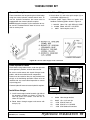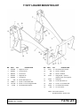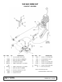
1
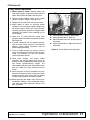
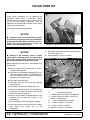
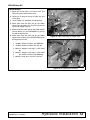
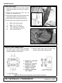
for 1020, 1027, LU126 Loaders on Ford/New Holland® 2000, 2310, 2600, 2610 2810, 2910, 3000, 3600 3610, 3910, 4000SU, 4100 4600SU, 4610SU, Tractors (Rev. 05/18/2010) MAN0064 includes Hose Kits 57923, 1001420 1023582, 1023596 HIS T E ! SAV NUAL MA e it with ual. an ud Incl ader M fety, r Lo ains sa epair u o y nt dr It co tion, an ation m r ra ope rt infor in othe pa und fo ls. not manua Tested. Proven. Unbeatable. INSTALLATION MANUAL 111877 LOADER MOUNTING KIT TO THE DEALER: Assembly and proper installation of this product is the responsibility of the Woods® dealer. Read manual instructions and safety rules. Make sure all items on the Dealer’s Pre-Delivery and Delivery Check Lists in the Loader Operator’s Manual are completed before releasing equipment to the owner. TO THE OWNER: Read this manual and Loader Operator’s Manual before operating your Woods equipment. The information presented will prepare you to do a better and safer job. Keep this manual handy for ready reference. Require all operators to read this manual carefully and become acquainted with all adjustment and operating procedures before attempting to operate. Replacement manuals can be obtained from your dealer. To locate your nearest dealer, check the Dealer Locator at www.WoodsEquipment.com, or in the United States and Canada call 1-800-319-6637. The equipment you have purchased has been carefully engineered and manufactured to provide dependable and satisfactory use. Like all mechanical products, it will require cleaning and upkeep. Lubricate the unit as specified. Observe all safety information in this manual and safety decals on the equipment. For service, your authorized Woods dealer has trained mechanics, genuine Woods service parts, and the necessary tools and equipment to handle all your needs. Use only genuine Woods service parts. Substitute parts will void the warranty and may not meet standards required for safe and satisfactory operation. Record the model number of your equipment in the space provided. Model: _______________________________ Date of Purchase: _____________________ Provide this information to your dealer to obtain correct repair parts. Throughout this manual, the term NOTICE is used to indicate that failure to observe can cause damage to equipment. The terms CAUTION, WARNING, and DANGER are used in conjunction with the Safety-Alert Symbol (a triangle with an exclamation mark) to indicate the degree of hazard for items of personal safety. 2 Introduction LMK (Rev. 7/20/2007) SAFETY RULES ATTENTION! BECOME ALERT! YOUR SAFETY IS INVOLVED! ! LEA EL INSTRUCTIVO! Si no lee Ingles, pida ayuda a alguien que si lo lea para que le traduzca las medidas de seguridad. Safety is a primary concern in the design and manufacture of our products. Unfortunately, our efforts to provide safe equipment can be wiped out by an operator’s single careless act. In addition to the design and configuration of equipment, hazard control and accident prevention are dependent upon the awareness, concern, judgement, and proper training of personnel involved in the operation, transport, maintenance, and storage of equipment. It has been said, “The best safety device is an informed, careful operator.” We ask you to be that kind of operator. INSTALLATION This Loader Mounting Kit is to be used only for the loaders and tractors specified in this manual. Any other use or modification of this mounting kit may result in serious injury or death. Hydraulics must be connected as instructed in this manual. Do not substitute parts, modify, or connect in any other way. After connecting hoses, check that all control lever positions function as instructed in the Operator's Manual. Do not put into service until control lever and equipment movements are correct. Safety instructions are important! Read all attachment and power unit manuals; follow all safety rules and safety decal information. (Replacement manuals and safety decals are available from your dealer. To locate your nearest dealer, check the Dealer Locator at www.WoodsEquipment.com, or in the United States and Canada call 1-800-3196637.) Failure to follow instructions or safety rules can result in serious injury or death. Keep hands and body away from pressurized lines. Use paper or cardboard, not hands or other body parts to check for leaks. Wear safety goggles. Hydraulic fluid under pressure can easily penetrate skin and will cause serious injury or death. Make sure that all operating and service personnel know that if hydraulic fluid penetrates skin, it Loader Mounting Kit SR3 (4/25/2003) must be surgically removed as soon as possible by a doctor familiar with this form of injury or gangrene, serious injury, or death will result. CONTACT A P HYS ICIA N IM ME DIATE LY IF FLU ID ENTERS SKIN OR EYES. DO NOT DELAY. Check that all hardware is properly installed. Always tighten to torque chart specifications unless instructed otherwise in this manual. Air in hydraulic systems can cause erratic operation and allows loads or equipment components to drop unexpectedly. When connecting equipment or hoses or performing any hydraulic maintenance, purge any air in hydraulic system by operating all hydraulic functions several times. Do this before p ut t i ng i n t o s e r v i c e o r a l l o w i n g a n y o n e t o approach the equipment. Protective hose sleeves must cover all hydraulic hoses within 20 inches of the operator and be secured onto metal hose fittings. Replace hoses or sleeves if damaged or if protective sleeve cannot be properly positioned or secured. Make sure all hydraulic hoses, fittings, and valves are in good condition and not leaking before starting power unit or using equipment. Check and route hoses carefully to prevent damage. Hoses must not be twisted, bent sharply, kinked, frayed, pinched, or come into contact with any moving parts. Operate moveable components through full operational range to check clearances. Replace any damaged hoses immediately. Always wear relatively tight and belted clothing to avoid getting caught in moving parts. Wear sturdy, rough-soled work shoes and protective equipment for eyes, hair, hands, hearing, and head; and respirator or filter mask where appropriate. Do not modify or alter or permit anyone else to modify or alter the equipment or any of its components in any way. Do not allow bystanders in the area when operating, attaching, removing, assembling, or servicing equipment. Use a suitable lifting device of sufficient capacity. Use adequate personnel to handle heavy components. Keep all persons away from operator control area while performing adjustments, service, or maintenance. Safety 3 LOADER MOUNT INSTALLATION WARNING ■ Only use 111877 Loader Mounting Kit for mounting Woods 1020, 1027, LU126 loaders on Ford New Holland 2000, 2310, 2600, 2610, 2810, 2910, 3000, 3600, 3610, 3910, 4000SU, 4100, 4600SU, and 4610SU tractors. Any other use or modification of this mounting kit may result in serious injury or death. Safety instructions are important! Read all attachment and power unit manuals; follow all safety rules and safety decal information. (Replacement manuals and safety decals are available from your dealer. To locate your nearest dealer, check the Dealer Locator at www.WoodsEquipment.com, or in the United States and Canada call 1-800-3196637.) Failure to follow instructions or safety rules can result in serious injury or death. CAUTION Always wear relatively tight and belted clothing to avoid getting caught in moving parts. Wear sturdy, rough-soled work shoes and protective equipment for eyes, hair, hands, hearing, and head; and respirator or filter mask where appropriate. NOTICE ■ This equipment must be assembled and installed on the customer’s tractor by the Woods dealer. Dealer must thoroughly inspect equipment and complete each item on the PRE-DELIVERY CHECK LIST, DELIVERY CHECK LIST, and PRODUCT REGISTRATION before equipment is released to the customer. ■ Clean threaded holes in the tractor chassis thoroughly using a tap of the proper size. Paint, rust, or debris in the threads may not permit cap screws to be installed and tightened correctly. TRACTOR PREPARATION For installing this mounting kit, references to right, left, forward, and rearward directions are determined from the operator’s position in the tractor seat. NOTE: Leave all loader mount hardware loose until mount is completely installed or otherwise instructed. 1. Shut off engine and set parking brake during installation. 2. Remove the tractor front weights and weight bracket if equipped. 3. Set tractor front wheel width to 61-1/2” (center line of thread) as instructed in tractor operator manual. 4. Remove cowl-mounted headlights if equipped. As a valued customer, Woods appreciates your comments. Once loader mount and hydraulic hoses have been installed, please take a few minutes to complete the Loader Mount Evaluation sheet that was supplied with your loader mount. Your comments will help us continue to bring you quality products. 4 Mount Installation MAN0064 (Rev. 7/20/2007) Install Right and Left Rear Mounts 1. Attach right rear mount (1) to the tractor clutch housing using two cap screws (12) and hardened flat washers (14) in the top holes and two cap screws (16) hardened flat washers (14) in the lower two holes. 1. 1026490 Right rear mount 2. 1026491 Left rear mount 12. 300517 3/4 NC x 1-3/4 HHCS GR5 14. 57798 3/4 Hardened flat washer 16. 735 3/4 NC x 2 HHCS GR5 2. Repeat to install left rear mount (2). 14 12 DP1 14 Figure 1. Rear Mount Installation (Rev. 05/18/2010) MAN0064 (Rev. 7/20/2007) 16 Figure 2. Left rear Mount Installed Mount Installation 5 Install Front Mount 1. Insert four (two per side) carriage bolts (13) into upper holes of front mount prior to attaching to tractor. Carriage bolts should be inserted from the inside pointing outward. 13 2. Attach front support (3) to tractor, using two cap screws (17) and hardened flat washers (15). 3. 1001642 Front mount 13. 301130 5/8 NC x 1-1/2 Carriage bolt GR5 15. 57817 5/8 Hardened flat washer 17. 902 5/8 NC x 2 HHCS GR5 15 DP2 17 Figure 3. Front Mount Installed Install Right and Left Side rails 1. Place front holes of right side rail (4) over carriage bolts (13) and front mount and secure with hardened flat washers (15) and hex nuts (10). 2. Attach side rail to inside of rear mount, using four carriage bolts (13), hardened flat washers (15) and hex nuts (10). Carriage bolts must be installed with heads on inside of rear mount as shown in Figure 6. 3. Repeat steps to install left side rail (5). 4. 1026492 Right side rail 5. 1026493 Left side rail 10. 230 5/8 NC Hex nut 13. 301130 5/8 NC x 1-1/2 Carriage bolt GR5 15. 57817 5/8 Hardened flat washer 10 15 Figure 4. Right Side Rail Installation 13 13 15 10 DP4 DP3 Figure 5. Side Rail to Front Mount 6 Mount Installation Figure 6. Side Rail to Rear Mount (Rev. 05/18/2010) MAN0064 (Rev. 7/20/2007) Install Grill Guard (Optional) Attach grill guard (21) to front mount (3) using four (two per side) cap screw (23), lock washers (25), hardened flat washers (24) and hex nuts (22). Torque hardware to: . . . . . . . .85 lbs-ft (115 N-m) 3. 1001642 Front mount 21. 57822 Grill guard 22. 1093 1/2 NC Hex nut 23. 3379 1/2 NC x 1-1/2 HHCS GR5 24. 57816 1/2 Hardened flat washer 25. 855 1/2 Lock washer Figure 7. Grill Guard Installation Torque Hardware Torque all hardware to specifications listed below. TORQUE SPECIFICATIONS Ref Cap Screw Qty Wrench Size Required Torque 12 3/4 NC x 1-3/4 4 1-1/8” 297 lbs.-ft. (403 N-m) 13 5/8 NC x 1-1/2 (Carriage Bolt) 12 15/16” 170 lbs.-ft. (230 N-m) 16 3/4 NC x 2 4 1-1/8” 297 lbs.-ft. (403 N-m) 17 5/8 NC x 1-1/2 2 15/16” 170 lbs.-ft. (230 N-m) MAN0064 (Rev. 7/20/2007) Mount Installation 7 NOTES 8 Mount Installation MAN0064 (Rev. 7/20/2007) HOSE KIT INSTALLATION WARNING WARNING Keep hands and body away from pressurized lines. Use paper or cardboard, not hands or other body parts to check for leaks. Wear safety goggles. Hydraulic fluid under pressure can easily penetrate skin and will cause serious injury or death. Protective hose sleeves must cover all hydraulic hoses within 20 inches of the operator and be secured onto metal hose fittings. Replace hoses or sleeves if damaged or if protective sleeve cannot be properly positioned or secured. Make sure that all operating and service personnel know that if hydraulic fluid penetrates skin, it must be surgically removed as soon as possible by a doctor familiar with this form of injury or gangrene, serious injury, or death will result. CONTACT A P HYS ICIA N IM ME DIATE LY IF FLU ID ENTERS SKIN OR EYES. DO NOT DELAY. Make sure all hydraulic hoses, fittings, and valves are in good condition and not leaking before starting power unit or using equipment. Check and route hoses carefully to prevent damage. Hoses must not be twisted, bent sharply, kinked, frayed, pinched, or come into contact with any moving parts. Operate moveable components through full operational range to check clearances. Replace any damaged hoses immediately. Air in hydraulic systems can cause erratic operation and allows loads or equipment components to drop unexpectedly. When connecting equipment or hoses or performing any hydraulic maintenance, purge any air in hydraulic system by operating all hydraulic functions several times. Do this before p ut t i ng i n t o s e r v i c e o r a l l o w i n g a n y o n e t o approach the equipment. 57923 Hose Kit Installation - - - - - - - - - - - - - - page 9 1001420 Hose Kit Installation - - - - - - - - - - - - page 12 1023582 Hose Kit Installation - - - - - - - - - - - - page 16 1023596 Hose Kit Installation - - - - - - - - - - - - page 19 57923 HOSE KIT General Description Install Hose Fittings These instructions are for operating the 1020/1027 loader using the tractor hydraulic remote control lever. To use this hydraulic connection, the tractor must be equipped with two hydraulic levers and four tractor hydraulic couplers. NOTE: Male quick couplers (3) for connection to tractor are NOT included with the hose kit but are available as service parts. 1. Attach elbow (2) and male quick coupler (3) to each loader supply hose (1). 2. Connect loader supply hoses to loader steel feedlines following pattern shown in Figure 8. 1. 2. 3. 57912 Hose, 120" x 1/2 JICM x JICM 313053 Elbow, 3/4 JICF x 1/2 NPTM 66511 Quick coupler, male 1/2 Figure 8. 1020/1027 Loader Supply Hose Connection MAN0064 (Rev. 7/20/2007) Hydraulic Installation 9 59723 Hose Kit Route Hydraulic Hoses Route hoses along loader mount, under the right side of the operator’s platform, and over the rear axle. /()7 6,'( +<'5$8/,& &21752/ ' Be sure to avoid contact with 3-point linkage, brake pedals, and other moveable tractor components. Hoses must be routed so they are not pinched, bent sharply, or chafed during operation. Hoses must not interfere with any tractor control operation or contact any moving parts. Connect hydraulic hoses to tractor hydraulic couplers as shown in Figure 9 when loader is attached to tractor. 5,*+7 6,'( +<'5$8/,& &21752/ % & $ &0D Figure 9. Hydraulic Hose Connection to Tractor Install Hose Hanger 1. Install hose hanger bracket beneath right side of the operator’s platform as shown in Figure 10. Use cap screw, flat washers, and lock nut as shown in Figure 11. 2. Route hoses through support and secure with lock pin (15). 11. 12. 13. 14. 15. 58033 6778 4378 6250 58047 Hose hanger bracket 5/16 NC Lock nut 5/16 Flat washer 5/16 NC x 1-1/4 HHCS 1/4 x 2-1/2 Lock pin +26( +$1*(5 &0$ Figure 10. Hose Hanger Installed Figure 11. Hose Hanger Assembly 10 Hydraulic Installation MAN0064 (Rev. 7/20/2007) 57923 Hose Kit Verify Control Movements 1. Mount loader to tractor: Remove mount pins from loader uprights. Align tractor with loader and slowly drive tractor into loader. Shut off tractor. &0 2. Connect loader feedline hoses to the loader control valve quick couplers. See Figure 19. 3. Comply with all safety rules and start the tractor. 4. Mount loader to tractor by activating bucket cylinders to raise or lower the loader uprights into the loader mounts. Slowly drive tractor forward, activating appropriate cylinders to engage loader completely into mounts. Insert mounting pins to secure loader. 5. Check that all tractor hydraulic control lever positions operate the loader movements correctly. See Figure 20. 6. If loader movements do not respond correctly, shut off tractor, relieve pressure, and reconnect properly. Loader control movements must be correct before proceeding. 7. Once all loader functions are correct, start the tractor and operate the loader to check for leaks. Purge any remaining air from the hydraulic system and check oil level. ● ● ● ● Control Handle 1 Forward - Boom down Control Handle 1 Back - Boom up Control Handle 2 Forward - Dump bucket or attachment Control Handle 2 Back - Roll back bucket or attachment Figure 12. Tractor Control Lever Operation 8. When hose routings and correct loader operations are verified, identify each circuit by placing a matching colored band around the male and female quick-disconnect coupler. The color-coded bands will make reinstallation easier once the loader has been removed from the tractor. 9. Attach the plastic tie straps (included in kit) every 20 inches around the hoses to keep them tightly bundled and away from contact with the ground or other moving parts on the tractor or loader. 10. Before operating the loader, make sure that the Pre-Delivery, Delivery, and Pre-Operation Check Lists from the Loader Operator’s Manual have been completed. MAN0064 (Rev. 7/20/2007) Hydraulic Installation 11 1001420 HOSE KIT General Description These set-up instructions are for operating the 1020/1027 loader using a single-lever control mounted on the right loader upright as shown Figure 13. To use this hydraulic connection, hose kit 1001420 must be connected between loader control valve and tractor hydraulics. Install control valve before proceeding. NOTICE ■ If hydraulic lines are not connected as shown in this manual, the control valve may be damaged. A blocked outlet (RETURN) or improper hose connection will cause pressurized oil to enter the return circuit and damage the valve. Figure 13. 2-Spool Control Valve Installed (Typical) Install Adapter Plate NOTICE ■ Removal of the accessory plate or remote valves with a load being held on the 3-point hitch will result in escape of high pressure oil and sudden, uncontrolled drop of 3-point hitch arms. Before attempting to install this kit, the following must be observed: ● Shut off engine, place transmission in neutral, 7. Secure with hex head cap screws and flat washer as shown in Figure 14. 8. Secure elbows (1) and (2) as shown. 15 13 11 A 14 1 and apply parking brake. ● Fully lower any equipment supported by the trac- tor remote hydraulic valves, if so equipped. Activate any remote valves to relieve all hydraulic pressure in the remote circuits. ● Fully lower the 3-point hitch. 3 1. Thoroughly clean the top front of the hydraulic accessory plate. 2 2. Install elbows (1) and (2) to adapter plate (3). 3. Remove accessory plate cover (A). Be careful not to disturb the O-rings that need to stay with the cover plate when it is removed. 4. Install O-rings to bottom of adapter plate (3). Use petroleum jelly to keep the O-rings in the counterbores. 5. Place the adapter plate over hydraulic opening. 6. Place the accessory plate cover onto the adapter plate. Make sure O-rings stay in the counterbores. 1 Figure 14. Adapter Plate Installed A. ----- Accessory plate cover 1. 316004 Elbow, 3/4 JICM x 3/4 ORBM 90° 2. 313032 Elbow, 3/4 JICM x 3/4 JICF 90° 3. 1001421 Adapter plate 11. 4378 5/16 Standard flat washer 13. 21548 5/16 NC x 3-1/4 HHCS 14. 21549 7/16 NC x 3 HHCS 15. 1001423 7/16 NC x 4-3/4 HHCS 12 Hydraulic Installation MAN0064 (Rev. 7/20/2007) 1001420 Hose Kit Install Hoses 1. Attach 90° end of hoses (7) to the IN, OUT and PBY ports of the loader control valve. 2. Locate the fill plug on the top of right rear axle and remove. 1 7 P 3. Install adapter (5) and elbow (6) into opening. N 4. Attach hose from the PBY port on the loader control valve to elbow (2) in the PBY (N) port on the front of adapter plate (3). 5. Attach hose from the IN port on the loader control valve to elbow (1) in the PRESSURE (P) port on the side of adapter plate. 6. Attach hose from the OUT port on the loader control valve to elbow (6) in the RETURN port on the top of the rear axle. 1. 316004 2. 313032 5. 1001419 or 5. 1001657 6. 60 7. 1001422 Elbow, 3/4 JICM x 3/4 ORBM 90° Elbow, 3/4 JICM x 3/4 JICF 90° Adapter, 7/8 O-ring F x 1-3/8 Trd M 2 7 Figure 15. Hose Connection at Adapter Plate 7 6 Adapter, 7/8 O-ring F x 1-5/8 Trd M Elbow, 3/4 JICM x 7/8 ORBM 90° Hose, 86" x 3/4 JICF x 3/4 JICF 5 Figure 16. RETURN Port Connection MAN0064 (Rev. 7/20/2007) Hydraulic Installation 13 1001420 Hose Kit Install Hose Hanger 1. Install hose hanger bracket (8) under platform between brake pedals and chassis as shown in Figure 17. 2. Secure with hex head cap screw (10), flat washers (11), and lock nut (12). 3. Route hoses through hose hanger bracket and up behind right platform as shown in Figure 18. 4. Secure hoses in hose hanger with lock pin (9). 5. Secure hoses every 20 inches with plastic ties. 8. 9. 10. 11. 12. 58033 58047 6250 4378 6778 Hose hanger bracket 1/4 x 2-1/2 Lock pin 5/16 NC x 1-1/4 HHCS 5/16 Standard flat washer 5/16 NC Lock nut Figure 17. Hose Hanger Installed Figure 18. Hose Routing Connect Loader Feedline Hoses 1. The control valve kit contains hoses assembled with quick couplers. Attach the hoses to loader feedlines, following the color pattern. 2. Connect loader supply hoses to control valve hydraulic couplers when attaching loader. Figure 19. Control Valve and 1020/1027 Loader Feedline Connections 14 Hydraulic Installation MAN0064 (Rev. 7/20/2007) 1001420 Hose Kit Verify Control Movements 1. Mount loader to tractor: Remove mount pins from loader uprights. Align tractor with loader and slowly drive tractor into loader. Shut off tractor. 2. Connect loader feedline hoses to the loader control valve quick couplers. See Figure 19. 3. Comply with all safety rules and start the tractor. 4. Mount loader to tractor by activating bucket cylinders to raise or lower the loader uprights into the loader mounts. Slowly drive tractor forward, activating appropriate cylinders to engage loader completely into mounts. Insert mounting pins to secure loader. 5. Check that all tractor hydraulic control lever positions operate the loader movements correctly. See Figure 20. 6. If loader movements do not respond correctly, shut off tractor, relieve pressure, and reconnect properly. Loader control movements must be correct before proceeding. 7. Once all loader functions are correct, start the tractor and operate the loader to check for leaks. Purge any remaining air from the hydraulic system and check oil level. ● ● ● ● ● ● Handle forward - Boom down Handle forward to limit - Float position Handle back - Boom up Handle right Dump bucket or attachment (slow) Handle right to limit Dump bucket or attachment (fast) Handle to left - Rollback bucket or attachment Figure 20. Single Lever Control Operation 8. When hose routings and correct loader operations are verified, identify each circuit by placing a matching colored band around the male and female quick-disconnect coupler. The color-coded bands will make reinstallation easier once the loader has been removed from the tractor. 9. Attach the plastic tie straps (included in kit) every 20 inches around the hoses to keep them tightly bundled and away from contact with the ground or other moving parts on the tractor or loader. 10. Before operating the loader, make sure that the Pre-Delivery, Delivery, and Pre-Operation Check Lists from the Loader Operator’s Manual have been completed. MAN0064 (Rev. 7/20/2007) Hydraulic Installation 15 1023582 HOSE KIT General Description These set up instructions are for operating the LU126 loader using a single lever control valve mounted to the right loader mount bracket as shown in Figure 21. To use this hydraulic connection, hose kit 1023582 must be connected between loader control valve and tractor hydraulics. Install loader control valve before proceeding. NOTICE ■ If hydraulic lines are not connected as shown in this manual, the control valve may be damaged. A blocked outlet (RETURN) or improper hose connection will cause pressurized oil to enter the return circuit and damage the valve. DP8 Figure 21. Control Valve Installed Install Adapter Plate NOTICE ■ Removal of the accessory plate or remote valves with a load being held on the 3-point hitch will result in escape of high pressure oil and sudden, uncontrolled drop of 3-point hitch arms. 6. Place the accessory plate cover onto the adapter plate. Make sure O-rings stay in the counterbores. 7. Secure with hex head cap screws and flat washer as shown in Figure 22. Before attempting to install this kit, the following must be observed: ● Shut off engine, place transmission in neutral, and apply parking brake. ● Fully lower any equipment supported by the trac- tor remote hydraulic valves, if so equipped. Activate any remote valves to relieve all hydraulic pressure in the remote circuits. ● Fully lower the 3-point hitch. 1. Thoroughly clean the top front of the hydraulic accessory plate. 2. Install elbow (12) and adapter (21) to adapter plate (2). 3. Remove accessory plate cover (A). Be careful not to disturb the O-rings that need to stay with the cover plate when it is removed. 4. Install O-rings to bottom of adapter plate (2). Use petroleum jelly to keep the O-rings in the counterbores. 5. Place the adapter plate over hydraulic opening. Figure 22. Adapter Plate Installed A. ----- Accessory plate cover 2. 1001421 Adapter plate 10. 1001423 7/16 NC X 4-3/4 HHCS 12. 316004 Elbow, 3/4 JICM x 3/4 ORBM 90° 15. 21549 7/16 NC x 3 HHCS 16. 21548 5/16 NC x 3-1/4 HHCS 19. 4378 5/16 Standard flat washer 21. 61 Adapter, 3/4 JICM x 3/4 ORBM 16 Hydraulic Installation MAN0064 (Rev. 7/20/2007) 1023582 Hose Kit Install Hoses 1. Attach straight end of hoses (1) to the IN, OUT and PBY ports of the loader control valve. 2. Locate the fill plug on the top of right rear axle and remove. 3. Install adapter (3) and adapter (11) into opening. 4. Attach hose from the PBY port on the loader control valve to elbow (12) in the PBY (N) port on the front of adapter plate (2). 5. Attach hose from the IN port on the loader control valve to adapter (21) in the PRESSURE (P) port on the side of adapter plate. 6. Attach hose from the OUT port on the loader control valve to adapter (11) in the RETURN port on the top of the rear axle. 1. 2. 3. 3. 11. 12. 21. 1001422 1001421 1001419 1001657 316016 316004 61 Hose, 86" x 3/4 JICF x 3/4 JICF Adapter plate Adapter, 7/8 O-ring F x 1-3/8 Trd M Adapter, 7/8 O-ring F x 1-5/8 Trd M Adapter, 3/4 JICM x 7/8 ORBM Elbow, 3/4 JICM x 3/4 ORBM 90° Adapter, 3/4 JICM x 7/8 ORBM 90° Figure 23. Hydraulic Fitting Installation Install Hose Hanger 1. Install hose hanger bracket (14) under platform between brake pedals and chassis as shown in Figure 24. 2. Secure with hex head cap screw (18), flat washers (19), and lock nut (17). 3. Route hoses through hose hanger bracket and up behind right platform as shown in Figure 18. 4. Secure hoses in hose hanger with lock pin (13). 5. Secure hoses every 20 inches with plastic ties. Figure 24. Hose Hanger Installed 14. 13. 17. 18. 19. 58033 58047 6778 6250 4378 Hose hanger bracket 1/4 x 2-1/2 Lock pin 5/16 NC Lock nut 5/16 NC x 1-1/4 HHCS 5/16 Standard flat washer Figure 25. Hose Routing MAN0064 (Rev. 7/20/2007) Hydraulic Installation 17 1023582 Hose Kit Connect Loader Feedline Hoses 1. The control valve kit contains hoses assembled with quick couplers. Attach the hoses to loader feedlines, following the color pattern. 2. Connect loader supply hoses to control valve hydraulic couplers when attaching loader. Figure 26. Control Valve & LU126 Loader Feedline Connections Verify Control Movements 1. Mount loader to tractor: Remove mount pins from loader uprights. Align tractor with loader and slowly drive tractor into loader. Shut off tractor. 2. Connect loader feedline hoses to the loader control valve quick couplers. See Figure 26. 3. Comply with all safety rules and start the tractor. 4. Mount loader to tractor by activating bucket cylinders to raise or lower the loader uprights into the loader mounts. Slowly drive tractor forward, activating appropriate cylinders to engage loader completely into mounts. Insert mounting pins to secure loader. 9. Attach the plastic tie straps (included in kit) every 20 inches around the hoses to keep them tightly bundled and away from contact with the ground or other moving parts on the tractor or loader. 10. Before operating the loader, make sure that the Pre-Delivery, Delivery, and Pre-Operation Check Lists from the Loader Operator’s Manual have been completed. 5. Check that all tractor hydraulic control lever positions operate the loader movements correctly. See Figure 27. 6. If loader movements do not respond correctly, shut off tractor, relieve pressure, and reconnect properly. Loader control movements must be correct before proceeding. ● 7. Once all loader functions are correct, start the tractor and operate the loader to check for leaks. Purge any remaining air from the hydraulic system and check oil level. ● 8. When hose routings and correct loader operations are verified, identify each circuit by placing a matching colored band around the male and female quick-disconnect coupler. The color-coded bands will make reinstallation easier once the loader has been removed. ● ● ● ● 18 Hydraulic Installation Handle forward - Boom down Handle forward to limit - Float position Handle back - Boom up Handle right Dump bucket or attachment (slow) Handle right to limit Dump bucket or attachment (fast) Handle to left - Rollback bucket or attachment Figure 27. Single Lever Control Operation MAN0064 (Rev. 7/20/2007) 1023596 HOSE KIT General Description Install Hose Fittings These instructions are for operating the LU126 loader using the tractor hydraulic remote control lever. To use this hydraulic connection, the tractor must be equipped with four tractor hydraulic couplers. NOTE: Male quick couplers (3) for connection to tractor are NOT included with the hose kit but are available as service parts. 1. Attach elbow (2) and male quick coupler (3) to each loader supply hose (1). 2. Connect loader supply hoses to loader steel feedlines. Following pattern shown in Figure 8. 1. 1023472 Hose, 170" x 3/4 JICM x 3/4 JICM 2. 313053 Elbow, 3/4 JICF x 1/2 NPTM 3. 66511 Quick coupler, male 1/2 Figure 28. LU126 Loader Supply Hose Connection Route Hydraulic Hoses Route hoses along loader mount, under the right side of the operator’s platform, and over the rear axle. Be sure to avoid contact with 3-point linkage, brake pedals, and other moveable tractor components. Hoses must be routed so they are not pinched, bent sharply, or chafed during operation. Hoses must not interfere with any tractor control operation or contact any moving parts. Connect hydraulic hoses to tractor hydraulic couplers. +26( +$1*(5 &0$ Install Hose Hanger 1. Install hose hanger bracket beneath right side of the operator’s platform as shown in Figure 29. Use cap screw, flat washers, and lock nut as shown in Figure 29. 2. Route hoses through support and secure with lock pin (12). MAN0064 (Rev. 7/20/2007) Figure 29. Hose Hanger Installed 4. 12. 15. 16. 17. 58033 58047 6778 6250 4378 Hose hanger bracket 1/4 x 2-1/2 Lock pin 5/16 NC Lock nut 5/16 NC x 1-1/4 HHCS 5/16 Standard flat washer Hydraulic Installation 19 1023596 Hose Kit Verify Control Movements 1. Mount loader to tractor: Remove mount pins from loader uprights. Align tractor with loader and slowly drive tractor into loader. Shut off tractor. &0 2. Connect loader feedline hoses to the loader control valve quick couplers. See Figure 19. 3. Comply with all safety rules and start the tractor. 4. Mount loader to tractor by activating bucket cylinders to raise or lower the loader uprights into the loader mounts. Slowly drive tractor forward, activating appropriate cylinders to engage loader completely into mounts. Insert mounting pins to secure loader. 5. Check that all tractor hydraulic control lever positions operate the loader movements correctly. See Figure 20. 6. If loader movements do not respond correctly, shut off tractor, relieve pressure, and reconnect properly. Loader control movements must be correct before proceeding. ● ● ● ● 7. Once all loader functions are correct, start the tractor and operate the loader to check for leaks. Purge any remaining air from the hydraulic system and check oil level. Control Handle 1 Forward - Boom down Control Handle 1 Back - Boom up Control Handle 2 Forward - Dump bucket or attachment Control Handle 2 Back - Roll back bucket or attachment Figure 30. Tractor Control Lever Operation 8. When hose routings and correct loader operations are verified, identify each circuit by placing a matching colored band around the male and female quick-disconnect coupler. The color-coded bands will make reinstallation easier once the loader has been removed from the tractor. 9. Attach the plastic tie straps (included in kit) every 20 inches around the hoses to keep them tightly bundled and away from contact with the ground or other moving parts on the tractor or loader. 10. Before operating the loader, make sure that the Pre-Delivery, Delivery, and Pre-Operation Check Lists from the Loader Operator’s Manual have been completed. 20 Hydraulic Installation MAN0064 (Rev. 7/20/2007) 111877 LOADER MOUNTING KIT REF PART QTY DESCRIPTION REF PART QTY DESCRIPTION 1 1026490 1 Right rear mount 15 2 1026491 1 Left rear mount 16 3 1001642 1 Front mount 17 2 5/8 NC x 2 HHCS 4 1026492 1 Right side rail 20 57913 1 5 1026493 1 Left side rail Grill guard kit - optional (includes items 21 through 25) 21 57822 1 Grill guard 10 12 13 14 230 * 12 5/8 NC Plated Hex nut 300517 * 4 3/4 NC x 1-3/4 HHCS GR5 301130 * 12 5/8 NC x 1-1/2 Carriage bolt GR5 57798 8 3/4 Hardened flat washer 57817 735 * 902 * 14 5/8 Hardened flat washer 8 3/4 NC x 2 HHCS 22 1093 * 4 1/2 NC Plated hex nut 23 3379 * 4 1/2 NC x 1-1/2 HHCS GR5 4 1/2 Hardened flat washer 4 1/2 Lock washer 24 25 57816 855 * HHCS Hex Head Cap Screw * Standard hardware, obtain locally (Rev. 05/18/2010) MAN0064 (Rev. 7/20/2007) Parts 21 1001420 HOSE KIT (1020/1027 LOADERS) REF PART QTY DESCRIPTION REF PART QTY DESCRIPTION A ——— 1 Accessory plate (tractor part) 10 6250 * 1 5/16 NC x 1-1/4 HHCS GR5 1 316004 2 Elbow, 3/4 JICM x 3/4 ORBM 90° 11 4378 * 3 5/16 Standard flat washer 2 313032 1 Elbow, 3/4 JICM x 3/4 JICF 90° 12 6778 * 1 5/16 NC Lock nut 3 1001421 1 Ford PBY Plate adapter 13 21548 * 1 5/16 NC x 3-1/4 HHCS GR8 5 1001419 1 Adapter, 7/8 O-ring F x 1-3/8 Trd M 14 21549 * 2 7/16 NC x 3 HHCS GR8 ZP 15 1001423 * 2 7/16 NC x 4-3/4 HHCS GR8 16 88 * 4 Plastic tie (not shown) - or 5 1001657 1 Adapter, 7/8 O-ring F x 1-5/8 Trd M 6 60 1 Elbow, 3/4 JICM x 7/8 ORBM 7 1001422 3 Hose, 86" x 3/4 JICF x 3/4 JICF 8 58033 1 Hose hanger bracket 9 58047 1 Pin lock 1/4 x 2-1/2 22 Parts HHCS Hex Head Cap Screw * Standard hardware, obtain locally MAN0064 (Rev. 7/20/2007) 1023582 HOSE KIT (LU126 LOADER) REF PART QTY DESCRIPTION A ——— 1 Accessory plate (tractor part) 1 1001422 3 Hose, 86" x 3/4 JICF x 3/4 JICF 2 1001421 1 Ford PBY Plate adapter 3 1001419 1 Adapter, 7/8 O-ring F x 1-3/8 Trd M 3 1001657 1 Adapter, 7/8 O-ring F x 1-5/8 Trd M 10 1001423 * 2 7/16 NC x 4-3/4 HHCS GR8 11 316016 1 Adapter, 3/4 JICM x 7/8 ORBM 12 316004 1 Elbow, 3/4 JICM x 3/4 ORBM 90° 13 58047 1 Pin lock 1/4 x 2-1/2 14 58033 1 Hose hanger bracket 15 21549 * 2 7/16 NC x 3 HHCS GR8 ZP 16 21548 * 1 5/16 NC x 3-1/4 HHCS GR8 17 6778 * 1 5/16 NC Lock nut 18 6250 * 1 5/16 NC x 1-1/4 HHCS GR5 19 4378 * 3 5/16 Standard flat washer 20 88 * 4 Plastic tie (not shown) 21 61 1 Adapter, 3/4 JICM x 3/4 ORBM - or - HHCS Hex Head Cap Screw * Standard hardware, obtain locally MAN0064 (Rev. 7/20/2007) Parts 23 57923 HOSE KIT (10120/1027 LOADERS) REF PART QTY DESCRIPTION 1 57912 4 Hose, 120" x 3/4 JICM x 3/4 JICM 2 313053 4 Elbow, 3/4 JICF x 1/2 NPTM 90° 3 66511 4 Quick coupler, male 1/2 (not included in kit) 11 58033 1 Hose hanger bracket 12 6778 * 1 5/16 NC Lock nut 13 4378 * 2 5/16 Flat washer 14 6250 * 1 5/16 NC x 1-1/4 HHCS GR5 15 58047 * 1 1/4 x 2-1/2 Lock pin 16 88 * Plastic tie straps (not shown) HHCS Hex Head Cap Screw * Standard hardware, obtain locally 1023596 HOSE KIT (LU126 LOADER) REF PART QTY DESCRIPTION 1 1023472 4 Hose, 170" x 3/4 JICM x 3/4 JICM 2 313053 4 Elbow, 3/4 JICF x 1/2 NPTM 90° 3 66511 4 Quick coupler, male 1/2 (not included in kit) 4 58033 1 Hose hanger bracket 12 58047 * 1 1/4 x 2-1/2 Lock pin 15 6778 * 1 5/16 NC Lock nut 16 6250 * 1 5/16 NC x 1-1/4 HHCS GR5 17 4378 * 2 5/16 Flat washer 18 88 * Plastic tie straps (not shown) HHCS Hex Head Cap Screw * Standard hardware, obtain locally 24 Parts MAN0064 (Rev. 7/20/2007) BOLT TORQUE CHART Always tighten hardware to these values unless a different torque value or tightening procedure is listed for a specific application. Fasteners must always be replaced with the same grade as specified in the manual parts list. Always use the proper tool for tightening hardware: SAE for SAE hardware and Metric for metric hardware. Make sure fastener threads are clean and you start thread engagement properly. All torque values are given to specifications used on hardware defined by SAE J1701 MAR 99 & J1701M JUL 96. SAE Bolt Head Identification SAE SERIES TORQUE CHART A SAE Grade 2 (No Dashes) SAE Grade 8 (6 Radial Dashes) SAE Grade 5 (3 Radial Dashes) MARKING ON HEAD A SAE 2 SAE 5 SAE 8 Diameter (Inches) Wrench Size lbs-ft N-m lbs-ft N-m lbs-ft N-m 1/4" 5/16" 7/16" 1/2" 6 12 8 17 10 19 13 26 14 27 18 37 3/8" 7/16" 9/16" 5/8" 23 36 31 48 35 55 47 75 49 78 67 106 1/2" 9/16" 3/4" 13/16" 55 78 75 106 85 121 115 164 120 171 163 232 5/8" 3/4" 15/16" 1-1/8" 110 192 149 261 170 297 230 403 240 420 325 569 7/8" 1" 1-5/16" 1-1/2" 306 467 416 634 474 722 642 979 669 1020 907 1383 A METRIC SERIES TORQUE CHART A Metric Bolt Head Identification 8.8 Metric Grade 8.8 10.9 Metric Grade 10.9 COARSE THREAD FINE THREAD MARKING ON HEAD MARKING ON HEAD A Diameter & Thread Pitch (Millimeters) Wrench Size N-m lbs-ft N-m lbs-ft N-m lbs-ft N-m lbs-ft Diameter & Thread Pitch (Millimeters) 6 x 1.0 10 mm 8 6 11 8 8 6 11 8 6 x 1.0 8 x 1.25 10 x 1.5 13 mm 16 mm 20 39 15 29 27 54 20 40 21 41 16 30 29 57 22 42 8 x 1.0 10 x 1.25 12 x 1.75 14 x 2.0 18 mm 21 mm 68 109 50 80 94 151 70 111 75 118 55 87 103 163 76 120 12 x 1.25 14 x 1.5 16 x 2.0 18 x 2.5 24 mm 27 mm 169 234 125 172 234 323 173 239 181 263 133 194 250 363 184 268 16 x 1.5 18 x 1.5 20 x 2.5 22 x 2.5 30 mm 34 mm 330 451 244 332 457 623 337 460 367 495 270 365 507 684 374 505 20 x 1.5 22 x 1.5 24 x 3.0 30 x 3.0 36 mm 46 mm 571 1175 421 867 790 1626 583 1199 623 1258 459 928 861 1740 635 1283 24 x 2.0 30 x 2.0 Typical Washer Installations Bolt Metric 8.8 Lock Washer Metric 10.9 Metric 8.8 Metric 10.9 Flat Washer 8/9/00 Bolt Torque & Size Charts (Rev. 3/28/2007) Appendix 25 BOLT SIZE CHART NOTE: Chart shows bolt thread sizes and corresponding head (wrench) sizes for standard SAE and metric bolts. SAE Bolt Thread Sizes 5/16 3/8 1/2 IN MM 5/8 3/4 7/8 1 2 3 4 5 6 7 25 50 75 100 125 150 175 Metric Bolt Thread Sizes 8MM 10MM 12MM 14MM 16MM 18MM ABBREVIATIONS AG .............................................................. Agriculture ASABE ....................American Society of Agricultural & Biological Engineers (formerly ASAE) ASAE....... American Society of Agricultural Engineers ATF................................Automatic Transmission Fluid BSPP............................. British Standard Pipe Parallel BSPTM ................ British Standard Pipe Tapered Male CV .................................................... Constant Velocity CCW.............................................. Counter-Clockwise CW .............................................................. Clockwise F .......................................................................Female FT .............................................................. Full Thread GA ..................................................................... Gauge GR (5, etc.)........................................... Grade (5, etc.) HHCS ........................................ Hex Head Cap Screw HT ...........................................................Heat-Treated JIC ................. Joint Industry Council 37° Degree Flare LH................................................................. Left Hand LT ...........................................................................Left m ........................................................................ Meter mm ............................................................... Millimeter M .......................................................................... Male 26 Appendix MPa ........................................................ Mega Pascal N ...................................................................... Newton NC...................................................... National Coarse NF ........................................................... National Fine NPSM .................... National Pipe Straight Mechanical NPT...........................................National Pipe Tapered NPT SWF......... National Pipe Tapered Swivel Female ORBM ...........................................O-Ring Boss - Male P .......................................................................... Pitch PBY.......................................................Power-Beyond psi ......................................... Pounds per Square Inch PTO......................................................Power Take Off QD ................................................... Quick Disconnect RH.............................................................. Right Hand ROPS........................... Roll-Over Protective Structure RPM ........................................ Revolutions Per Minute RT ........................................................................Right SAE.......................... Society of Automotive Engineers UNC ..................................................... Unified Coarse UNF .......................................................... Unified Fine UNS ..................................................... Unified Special Bolt Torque & Size Charts (Rev. 3/28/2007) WARRANTY All Models Except Mow’n MachineTM Zero-Turn Mowers Please Enter Information Below and Save for Future Reference. Date Purchased: ____________________________ From (Dealer): __________________________________________ Model Number: ____________________________ Serial Number: __________________________________________ Woods Equipment Company (“WOODS”) warrants this product to be free from defect in material and workmanship. Except as otherwise set forth below, the duration of this Warranty shall be for TWELVE (12) MONTHS COMMENCING ON THE DATE OF DELIVERY OF THE PRODUCT TO THE ORIGINAL PURCHASER. All current model loaders and backhoes are warranted for two (2) years from the date of delivery to the original purchaser. The warranty periods for specific parts or conditions are listed below: Part or Condition Warranted Gearbox Seals Gearbox components Blade spindles Rust-through Model Number Duration (from date of delivery to the original purchaser) All units listed below 2 years BW1260, BW1620, BW1800, BW2400 8 years BW240HD, BW180HD, BW180HB, BW126HB 7 years BB48X, BB60X, BB72X, BB84X, BB600X, BB720X, BB840X, BB6000X, BB7200X, BB8400X, DS1260, DSO1260, DS1440, TS1680, BW126-3, BW180-3, BW240 6 years PHD25, PHD35, PHD65, PHD95, 2162, 3240, DS96, DS120, RCC42, RM550-2, RM660-2, RM9903, PRD6000, PRD7200, PRD8400, 7144RD-2, 9180RD-2, 9204RD-2, S15CD, S20CD, S22CD, S25CD, S27CD, BW180LH, TC/R74, TC/R68, TC/R60 5 years RDC54, RD60, RD72, TBW150C, TS/R60, TS/R52, TS/R44 3 years (1 year if used in rental or commercial applications) RM550-2, RM660-2, RM990-3, PRD6000, PRD7200, PRD8400, 7144RD-2, 9180RD-2, 9204RD-2 3 years BB600, BB720, BB840, BB6000, BB7200, BB8400, BW126-3, BW126HB, BW180-3, BW180HB, BW180HD, BW1260, BW1800, BW240, BW240HD, 2162, 3240, DS1260, DSO1260, DS1440, TS1680 10 years Under no circumstances will this Warranty apply in the event that the product, in the good faith opinion of WOODS, has been subjected to improper operation, improper maintenance, misuse, or an accident. This Warranty does not apply in the event that the product has been materially modified or repaired by someone other than WOODS, a WOODS authorized dealer or distributor, and/or a WOODS authorized service center. This Warranty does not cover normal wear or tear, or normal maintenance items. This Warranty also does not cover repairs made with parts other than those obtainable through WOODS. This Warranty is extended solely to the original purchaser of the product. Should the original purchaser sell or otherwise transfer this product to a third party, this Warranty does not transfer to the third party purchaser in any way. There are no third party beneficiaries of this Warranty. WOODS makes no warranty, express or implied, with respect to engines, batteries, tires or other parts or accessories not manufactured by WOODS. Warranties for these items, if any, are provided separately by their respective manufacturers. WOODS’ obligation under this Warranty is limited to, at WOODS’ option, the repair or replacement, free of charge, of the product if WOODS, in its sole discretion, deems it to be defective or in noncompliance with this Warranty. The product must be returned to WOODS with proof of purchase within thirty (30) days after such defect or noncompliance is discovered or should have been discovered, routed through the dealer and distributor from whom the purchase was made, transportation charges prepaid. WOODS shall complete such repair or replacement within a reasonable time after WOODS receives the product. THERE ARE NO OTHER REMEDIES UNDER THIS WARRANTY. THE REMEDY OF REPAIR OR REPLACEMENT IS THE SOLE AND EXCLUSIVE REMEDY UNDER THIS WARRANTY. THERE ARE NO WARRANTIES WHICH EXTEND BEYOND THE DESCRIPTION ON THE FACE OF THIS WARRANTY. WOODS MAKES NO OTHER WARRANTY, EXPRESS OR IMPLIED, AND WOODS SPECIFICALLY DISCLAIMS ANY IMPLIED WARRANTY OF MERCHANTABILITY AND/OR ANY IMPLIED WARRANTY OF FITNESS FOR A PARTICULAR PURPOSE. WOODS shall not be liable for any incidental or consequential losses, damages or expenses, arising directly or indirectly from the product, whether such claim is based upon breach of contract, breach of warranty, negligence, strict liability in tort or any other legal theory. Without limiting the generality of the foregoing, Woods specifically disclaims any damages relating to (i) lost profits, business, revenues or goodwill; (ii) loss of crops; (iii) loss because of delay in harvesting; (iv) any expense or loss incurred for labor, supplies, substitute machinery or rental; or (v) any other type of damage to property or economic loss. This Warranty is subject to any existing conditions of supply which may directly affect WOODS’ ability to obtain materials or manufacture replacement parts. No agent, representative, dealer, distributor, serviceperson, salesperson, or employee of any company, including without limitation, WOODS, its authorized dealers, distributors, and service centers, is authorized to alter, modify, or enlarge this Warranty. Answers to any questions regarding warranty service and locations may be obtained by contacting: Woods Equipment Company 2606 South Illinois Route 2 Post Office Box 1000 Oregon, Illinois 61061 USA 800-319-6637 tel 800-399-6637 fax www.WoodsEquipment.com F-3079 (Rev. 3/31/2010) WARRANTY (Replacement Parts For All Models Except Mow’n MachineTM Zero-Turn Mowers and Woods BoundaryTM Utility Vehicles) Woods Equipment Company (“WOODS”) warrants this product to be free from defect in material and workmanship for a period of ninety (90) days from the date of delivery of the product to the original purchaser with the exception of V-belts, which will be free of defect in material and workmanship for a period of 12 months. Under no circumstances will this Warranty apply in the event that the product, in the good faith opinion of WOODS, has been subjected to improper operation, improper maintenance, misuse, or an accident. This Warranty does not cover normal wear or tear, or normal maintenance items. This Warranty is extended solely to the original purchaser of the product. Should the original purchaser sell or otherwise transfer this product to a third party, this Warranty does not transfer to the third party purchaser in any way. There are no third party beneficiaries of this Warranty. WOODS’ obligation under this Warranty is limited to, at WOODS’ option, the repair or replacement, free of charge, of the product if WOODS, in its sole discretion, deems it to be defective or in noncompliance with this Warranty. The product must be returned to WOODS with proof of purchase within thirty (30) days after such defect or noncompliance is discovered or should have been discovered, routed through the dealer and distributor from whom the purchase was made, transportation charges prepaid. WOODS shall complete such repair or replacement within a reasonable time after WOODS receives the product. THERE ARE NO OTHER REMEDIES UNDER THIS WARRANTY. THE REMEDY OF REPAIR OR REPLACEMENT IS THE SOLE AND EXCLUSIVE REMEDY UNDER THIS WARRANTY. THERE ARE NO WARRANTIES WHICH EXTEND BEYOND THE DESCRIPTION ON THE FACE OF THIS WARRANTY. WOODS MAKES NO OTHER WARRANTY, EXPRESS OR IMPLIED, AND WOODS SPECIFICALLY DISCLAIMS ANY IMPLIED WARRANTY OF MERCHANTABILITY AND/ OR ANY IMPLIED WARRANTY OF FITNESS FOR A PARTICULAR PURPOSE. WOODS shall not be liable for any incidental or consequential losses, damages or expenses, arising directly or indirectly from the product, whether such claim is based upon breach of contract, breach of warranty, negligence, strict liability in tort or any other legal theory. Without limiting the generality of the foregoing, Woods specifically disclaims any damages relating to (i) lost profits, business, revenues or goodwill; (ii) loss of crops; (iii) loss because of delay in harvesting; (iv) any expense or loss incurred for labor, supplies, substitute machinery or rental; or (v) any other type of damage to property or economic loss. This Warranty is subject to any existing conditions of supply which may directly affect WOODS’ ability to obtain materials or manufacture replacement parts. No agent, representative, dealer, distributor, service person, salesperson, or employee of any company, including without limitation, WOODS, its authorized dealers, distributors, and service centers, is authorized to alter, modify, or enlarge this Warranty. Answers to any questions regarding warranty service and locations may be obtained by contacting: F-8494 (Rev. 6/23/2005)