1
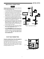
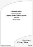
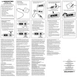
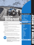
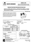
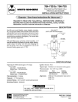
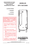
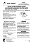
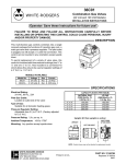
Type 36C74
Combination Gas Valve
WHITE-RODGERS
INSTALLATION INSTRUCTIONS
Operator: Save these instructions for future use!
FAILURE TO READ AND FOLLOW ALL INSTRUCTIONS CAREFULLY BEFORE
INSTALLING OR OPERATING THIS CONTROL COULD CAUSE PERSONAL INJURY
AND/OR PROPERTY DAMAGE.
DESCRIPTION
The 36C74 Gas Valve is for use on systems providing
automatic ignition of the pilot and/or main burners and
incorporates the following features: pilot/redundant solenoid valve, main valve, integral pressure regulator and
male spade terminals for point-to-point wiring.
ON
OFF
This gas valve is also equipped with a step-opening
feature to provide for quieter main burner ignition. The
valve opens partially until main burner flame is established, then the valve opens to full operating pressure.
SPECIFICATIONS
Electrical Rating:
24 VAC (30 Volts max. Voltage), 60 Hz.
PIPE SIZES/CAPACITIES
Types of Gases: Natural or LP Gas
Pressure Rating: 14” W.C. (1⁄2 PSI)
Ambient Temperature: -40° to 175°F (-40° to 79°C)
Regulator Adjustment Range:
Natural Gas: 2.5” to 5.0” W.C. (Full flow)
LP Gas: 7.5” to 12.0” W.C. (Full flow)
(Step pressure not adjustable)
Pipe Size
(inches)
1
/2" x 3/8"
1
/2" x 1/2"
1
/2" x 3/4"
3
/4" x 3/4"
Capacity (BTU/hr) at
1" pressure drop across valve
Nat. Gas
LP Gas
(1000 BTU/cu. ft., (2500 BTU/cu. ft.,
64 Sp. Gr.)
1.53 Sp. Gr.)
100,000
162,000
230,000
372,600
230,000
372,600
280,000
453,600
Upright, 90° from upright or vertical
1
1
2
3
LEFT OR RIGHT
ON
OFF
CONTENTS
Description .........................................................
Specifications .....................................................
Precautions ........................................................
Installation ..........................................................
Main Piping Connection
Pilot Gas Connection
System Wiring
Adjustment .........................................................
Pilot Flame Adjustment
Pressure Regulator Adjustment
Pilot Lighting Instructions and Precautions ........
WHITE-RODGERS DIVISION
EMERSON ELECTRIC CO.
9797 REAVIS ROAD
ST. LOUIS, MISSOURI 63123-5398
INLET BOSS
UP OR DOWN
UPRIGHT
4
NOTE: Control shown may not be identical
to replacement control.
5
Printed in U.S.A.
Figure 1. Mounting Positions
PART NO. 37-5868A
Replaces 37-5153A
9732
PRECAUTIONS
DO NOT BEGIN INSTALLATION UNTIL YOU READ
THE FOLLOWING PRECAUTIONS.
!
WARNING
If you do not follow these instructions exactly, a fire or explosion may
result, causing property damage, personal injury or loss of life.
1. Failure to turn off electric or main gas supply
to heating system could cause personal injury and/or property damage by shock, gas
suffocation, fire, and/or explosion.
4. DO NOT USE WIRE JUMPER on pilot systems, such as standing pilot, proven pilot, or
spark-to-pilot ignition–a fire and/or explosion may result.
2. Do not use this control on circuits exceeding
specified voltage. Higher voltage will damage the control and may cause shock or fire
hazard.
5. Do not use a control set for natural gas with
LP gas, or a control set for LP gas with
natural gas. Personal injury and/or property
damage, gas suffocation, fire, and/or explosion may result.
3. NEVER USE FLAME OR ANY KIND OF SPARK
TO CHECK FOR GAS LEAKS–COULD CAUSE
FIRE AND/OR EXPLOSION.
!
CAUTION
2. This control is not intended for use in locations where it may come in direct contact
with water. Suitable protection must be provided to shield the control from exposure to
water (dripping, spraying, rain, etc.).
1. Do not short out terminals on gas valve or
primary control to test. Short or incorrect
wiring can cause equipment damage, property damage, and/or personal injury.
2
INSTALLATION
MAIN PIPING CONNECTIONS
Drop
NOTE
Horizontal
All piping must comply with local codes, ordinances,
and/or national fuel gas codes.
1. Turn off electrical power to the system at the fuse box
or circuit breaker. Also turn off the main gas supply.
2. If replacing an existing valve, disconnect all plumbing
and electrical connections from the old control.
3. The valve may be installed in any position except
upside down. The arrow on the bottom plate indicates the direction of gas flow through the valve.
4. You should use new pipe that is properly chamfered,
reamed, and free of burrs and chips. If you are using
old pipe, be sure it is clean and free of rust, scale,
burrs, chips, and old pipe joint compound.
5. Apply pipe joint compound (pipe dope) or teflon tape
that is approved for all gases, only to the male
threads of the pipe joints. DO NOT apply compound or teflon tape to the first two threads (see fig. 2
for typical piping connections).
6. If you are using a vise or open-end wrench to hold the
valve while installing piping, do not tighten excessively, as this may damage the valve.
7. See SYSTEM WIRING when making electrical connections. After all gas and electrical connections are
completed, turn gas on and check for gas leaks with
leak detection solution or soap suds. Bubbles forming
indicate a leak. SHUT OFF GAS AND FIX ALL
LEAKS IMMEDIATELY.
NOTE:
Always Include
A Drip Leg In Piping
Riser
Gas Valve
3 in.
minimum
Drop
Tubing Gas
Supply
Gas Valve
Riser
Horizontal
Gas Valve
3 in.
minimum
3 in.
minimum
Piped Gas
Supply
Piped Gas
Supply
Figure 2. Typical gas valve piping
PILOT GAS CONNECTION
The valve is shipped with the pilot outlet plugged. For
installations requiring pilot gas, remove the plug and use
the fitting packed separately with the control.
Pilot Gas
Outlet
Install fitting into pilot gas outlet (see fig. 3), turning until
finger-tight. Insert clean, deburred tubing all the way
through the fitting. While holding the tubing securely,
slowly tighten fitting until you feel a slight “give”. Tighten
the fitting an additional 11⁄2 turns.
PILOT
PRESS
TAP
Gas Outlet
Figure 3. Gas valve side view
3
INSTALLATION (con’t)
SYSTEM WIRING
NOTE
All wiring should be installed in accordance with local and
national electrical codes and ordinances.
REFER TO AND FOLLOW THE APPLIANCE
MANUFACTURER’S WIRING DIAGRAM. REFER TO
FIG. 4 FOR TERMINAL IDENTIFICATION.
Check that the electrical power supply used agrees with
the voltage and frequency shown on the gas control.
Main Valve
1
2
Redundant
Valve Coil
(Pilot Valve)
3
4
Figure 4. Typical gas valve wiring
ADJUSTMENT
PILOT FLAME ADJUSTMENT
PRESSURE REGULATOR
ADJUSTMENT
This control was factory preset and will not normally
require additional adjustment of pilot flame.
The pressure regulator has been factory adjusted for
3.5” W.C. (Natural Gas, full flow) or 11.0” W.C. (LP Gas,
full flow). Although additional adjustments will not normally be necessary, the regulator may be adjusted if
required. Do not force the adjusting screw beyond the
limits that it can easily be adjusted.
If the pilot flame is low and does not engulf the bulb of the
mercury flame sensor, the system will not energize the
main valve.
If pilot gas pressure is too high, gas will sputter past the
ignition electrode, and may not ignite. High pilot gas
pressure may also cause the flame to lift off the burner,
causing the flame sensor bulb to sense “low” heat.
1. Attach a manometer to the outlet pressure tap of the
valve.
2. Energize valve to ignite main burner.
3. Remove “Reg. Adj.” cover screw (see fig. 6).
4. To DECREASE outlet pressure, turn the adjusting
screw (beneath the cover screw) counterclockwise.
To INCREASE outlet pressure, turn the adjusting
screw clockwise.
5. Replace the cover screw. Cycle the valve two or three
times to verify regulator setting.
To adjust the pilot flame, remove the pilot adjust cover
screw and gasket (see fig. 6) to expose adjusting screw.
To REDUCE pilot flame, turn the pilot adjust screw
clockwise. To INCREASE pilot flame, turn the pilot
adjust screw counterclockwise. Replace and tighten cover
screw and gasket.
Pilot Adjust
Cover Screw
NATURAL-LP
GAS SELECTOR
Gasket
REGULATOR
COVER SCREW
ON
OFF
PILOT ADJUST
COVER SCREW
Pilot
Adjust
Screw
Figure 5. Pilot flame adjustment
Figure 6. Gas valve top
4
PILOT LIGHTING INSTRUCTIONS
AND PRECAUTIONS
FOR YOUR SAFETY READ BEFORE LIGHTING
!
If you do not follow these instructions exactly, a fire or explosion
may result causing property damage, personal injury or loss of life.
WARNING
A. This appliance is equipped with an intermittent ignition
device which automatically lights the pilot. Do NOT try to
light the pilot by hand.
phone. Follow the gas supplier’s instructions.
•
B. BEFORE LIGHTING, smell all around the appliance area
for gas. Be sure to smell next to the floor because some
gas is heavier than air and will settle on the floor.
C. Use only your hand to push in or turn the gas control knob.
Never use tools. If the knob will not push in or turn by
hand, don’t try to repair it; call a qualified service technician. Force or attempted repair may result in a fire of
explosion.
FOR YOUR SAFETY
“WHAT TO DO IF YOU SMELL GAS”
•
Do not try to light any appliance.
•
Do not touch any electrical switch; do not use any
phone in your building.
•
Immediately call you gas supplier from a neighbor’s
If you cannot reach your gas supplier, call the fire
department.
D. Do not use this appliance if any part has been under water.
Immediately call a qualified service technician to inspect
the appliance and to replace any part of the control system
and any gas control that has been under water.
LIGHTING INSTRUCTIONS
1. STOP! Read the precautionary information above.
7. Wait five (5) minutes to clear out any gas. If you then smell
gas, STOP! Follow B in the precautionary information
above. If you don’t smell gas, go to next step.
2. Set the thermostat to lowest setting.
3. Turn off all electrical power to the appliance.
8. Turn knob on gas control counterclockwise to ON.
4. This appliance is equipped with an intermittent ignition
device which automatically lights the pilot. Do NOT try to
light the pilot by hand.
9. Replace pilot access panel(s).
10. Turn on all electrical power to the appliance.
5. Remove the pilot access panel(s) located under the gas
control unit.
11. Set thermostat to desired setting.
12. If the appliance will not operate, follow the instructions “To
Turn Off Gas To Appliance” and call your service technician or gas supplier.
6. Push in gas control knob slightly and turn clockwise to
OFF (see Figure 7).
NOTE: Knob cannot be turned to OFF unless knob is
depressed slightly. Do not use tools or excessive force.
TO TURN OFF GAS TO APPLIANCE
1. Set the thermostat to lowest setting.
4. Depress gas control knob slightly and turn clockwise to
OFF. Do not use tools or excessive force.
2. Turn off all electrical power to the appliance if service is to
be performed.
5. Replace control access panel.
3. Remove control access panel
ON
OFF
Gas Cock
Knob
Indicator
Figure 7. Gas Cock Knob
5
If you need more information about this product, please write to us at:
WHITE-RODGERS DIVISION, Emerson Electric Co.
9797 Reavis Road
St. Louis, MO 63123-5398
Attn: Technical Service Department