1
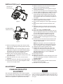
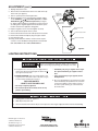
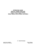
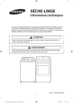
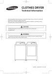
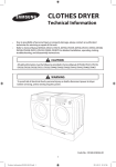
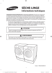
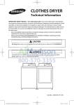
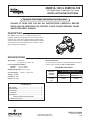
25M01A-100 to 25M01A-199
HSI Single Stage Combination Gas Valve
INSTALLATION INSTRUCTIONS
Operator: Save these instructions for future use!
FAILURE TO READ AND FOLLOW ALL INSTRUCTIONS CAREFULLY BEFORE
INSTALLING OR OPERATING THIS CONTROL COULD CAUSE PERSONAL INJURY
AND/OR PROPERTY DAMAGE.
DESCRIPTION
The 25M01A series valve is a combination gas pressure
regulator and dual automatic gas valve. These valves are designed for gas clothes dryers with Hot Surface Ignition (HSI)
systems. These valves are equipped with redundant and main
solenoid valves that control the gas flow to the burner, and a
direct acting pressure regulator.
SPECIFICATIONS
Type of Gas:
Mounting Positions:
Control may be mounted in the following positions: horizontal,
vertical or 90° of horizontal. NOT UPSIDE DOWN.
Natural gas
LP gas (use conversion kit)
Pressure Regulator Setting:
Nat. Gas – 2.5" to 5.4" W.C.
LP Gas – 7.0 to 12.0"W.C.
PIPE SIZES/CAPACITIES
Ambient Temperature: 32° to 155°F
Pressure Rating:
Pipe Sizes
Available
(inches)
14" W.C. (1/2 PSI) max.
Voltage: 120 VAC
Frequency: 60 Hz
Current: .06 amps
3/8"
NPT
Inlet
Capacity (BTU/hr) at
1” pressure drop across valve
AGA Std. Nat. Gas
LP Gas
(1,000 BTU/cu. ft.) (2,500 BTU/cu. ft.)
40,000
65,000
CONTENTS
Description .........................................................
Specifications .....................................................
Precautions ........................................................
Installation ..........................................................
Adjustment .........................................................
Pressure Regulator Adjustment
Lighting Instructions............................................
1
1
2
2
3
4
PART NO. 37-6643B
www.white-rodgers.com
www.emersonclimate.com
Replaces 37-6643A
1207
PRECAUTIONS
DO NOT BEGIN INSTALLATION UNTIL YOU READ THE
FOLLOWING PRECAUTIONS.
!
WARNING
If you do not follow these instructions exactly, a fire or explosion may
result, causing property damage, personal injury or loss of life.
3. NEVER USE FLAME OR ANY KIND OF SPARK TO
CHECK FOR GAS LEAKS–COULD CAUSE FIRE
AND/OR EXPLOSION.
1. Failure to turn off electric or main gas supply to
clothes dryer could cause personal injury and/or
property damage by shock, gas suffocation, fire,
and/or explosion.
4. Do not use a control set for natural gas with LP gas,
or a control set for LP gas with natural gas. Personal
injury and/or property damage, gas suffocation, fire,
and/or explosion may result.
2. Do not use this control on circuits exceeding specified voltage. Higher voltage will damage the control
and may cause shock or fire hazard.
!
CAUTION
2. This control is not intended for use in locations
where it may come in direct contact with water.
Suitable protection must be provided to shield the
control from exposure to water (dripping, spraying,
rain, etc.).
1. Do not short out terminals on gas valve or primary
control to test. Short or incorrect wiring can cause
equipment damage, property damage, and/or personal injury.
INSTALLATION
1. Before attempting to service dryer, unplug power cord,
turn off main gas supply and consult dryer manufacturer's
instructions for accessing gas valve.
2. Disconnect exhaust vent duct.
3. Disconnect gas line from rear of dryer.
4. Remove access panel from dryer. On some models this
involves removing the entire front panel.
5. The gas valve/burner assembly should now be visible.
6. The burner assembly consists of (see figure 1 & 2):
a. Gas inlet pipe.
b. Brass inlet fitting with union – some models may also
have a manual shut-off valve.
c. Gas valve.
d. Mounting bracket.
e. Burner orifice.
f. Burner assembly with air shutter.
g.Igniter.
h. Radiant sensor – located on heat exchanger on
some models.
7. Disconnect the wiring harness from gas valve and igniter.
8. Remove screw(s) fastening the mounting bracket to the
bottom of dryer.
9. Burner assembly should now be free to slide out of the
front of dryer. Take care not to bump or jar igniter. It is
very fragile.
10.Remove the gas inlet pipe by unscrewing the union.
11.Remove screw(s) fastening the gas valve to the mounting
bracket and set them aside. They will be reused.
12.The gas valve should now be free to slide out of burner
and off of mounting bracket. Take care not to disturb the
air shutter.
G
H
E (not shown)
F
G
H
A
B shown) F
E (not
C
C
A
Figure 1
E
B
C
Figure 2
B
D
C
2
B
D
E
INSTALLATION (cont.)
19. Slide the outlet boss of the new valve into the burner.
Take care not to disturb the air shutter.
20. Fasten the gas valve to the mounting bracket using the
screw(s) removed earlier.
21. Connect the gas inlet pipe to the inlet fitting by threading
the union together and tightening to 150 lbf-in (12.5 lbf-ft).
22. Insert the burner assembly back into the dryer so that
the gas inlet pipe exits through the square hole in the
back of the dryer cabinet, and the burner fits inside the
heat exchanger. Take care not to bump or jar igniter. It is
very fragile.
23. Fasten the mounting bracket to the bottom of the dryer
cabinet using the screw removed earlier.
24. Reconnect the wiring harness to the igniter and the gas
valve.
25. Reconnect the exhaust vent duct to the back of the
dryer.
26. Apply pipe sealant to the threads of the inlet gas pipe
and reconnect the gas line to the back of the dryer and
tighten.
27. Turn on gas supply and Check for leaks.
28. Remove the outlet pressure tap from the gas valve (see
figure 3). Apply pipe sealant to the 1/8-inch NPT threads
of a hose barb. Install the hose barb into the outlet
pressure tap and tighten to 40 lbf-in (see figure 4).
29. Connect a manometer to the hose barb. Manometer
should be capable of measuring pressure from 2.5" WC
up to 14.0" WC.
30. If entire front cover was removed, the connector for the
door switch must be temporarily jumpered. Otherwise
the dryer will not function.
Outlet Pressure
Tap (Plugged)
Figure 3
Hose Barb Installed
in Outlet Pressure Tap
Figure 4
NOTE: On some dryers, the front cover supports the
drum. On these models, the drum must be removed in
order to energize the system and adjust the regulator.
31. Plug dryer power cord into electrical socket.
32. Energize dryer and verify ignition. Also observe the
reading on the manometer. It should read the same
outlet pressure as stated on the rating plate on the old
gas valve. If it does not, see section on Pressure
Regulator Adjustment.
33. De-energize the dryer.
34. Remove the hose barb.
35. Apply pipe sealant to the 1/8 inch NPT plug screw. Install
the 1/8 inch NPT plug screw into the outlet pressure tap
and tighten 40 lbf-in.
36. Check for leaks.
37. Remove temporary jumper from door switch connector
and reconnect to door switch.
38. Reinstall the access panel/front cover.
13. Remove inlet fitting from old gas valve and set it aside.
Take care not to damage the sealing surfaces. This part
will be reused.
14. Clean the threads of the inlet fitting. Apply pipe sealant
(approved for all gases) to the threads. Install the fitting
into the inlet of the new valve and tighten to 200 lbf-in
(16.6 lbf-ft) using a 3/8 inch hex head wrench.
15. Remove orifice screw from old gas valve and set it
aside. Take care not to damage the sealing surfaces. This part will be reused.
16. Inspect the threads of the orifice screw and clean if
necessary.
17. Inspect the orifice hole and remove any foreign material.
18. Install orifice screw into new valve and tighten to 40 lbf in. Do not use any pipe sealant.
ADJUSTMENT
PRESSURE REGULATOR
ADJUSTMENT
NOTE
This control was shipped from the factory with the regulator
set as specified on the control label. Consult the appliance rating plate to ensure burner manifold pressure is as specified. If
outlet pressure adjustment is required, follow these steps.
If a valve has been factory-adjusted for the 2.5 to 5 inches W.C.
range, it cannot be field-adjusted outside that range. This is
also true for valves adjusted to the 7.0 to 12 inches W.C. range
for LP gas.
3
ADJUSTMENT (cont.)
1. Unplug dryer power cord.
2. Attach a hose and manometer to the hose barb in the tap
of the valve (see figure 5).
3. Turn on system power and energize valve.
4. Remove regulator cover screw and turn regulator adjust
screw clockwise (
) to increase pressure, or counterclockwise (
) to decrease pressure (see figure
6). Always adjust regulator to provide the correct pressure
according to the original equipment manufacturer’s specifications listed on the appliance rating plate.
5. Replace regulator cover screw and tighten securely.
6. Turn off all electrical power to the system.
7. Remove manometer hose from outlet pressure hose barb.
8. Remove hose barb and replace plug. Use pipe sealant.
9. Plug in power cord.
10.Using a leak detection solution, check for leaks at pressure boss screw. Bubbles forming indicate a leak. SHUT
OFF GAS AND FIX ALL LEAKS IMMEDIATELY.
REGULATOR
ADJUSTMENT
TOWER
Figure 5
HOSE BARB
INSTALLED
REGULATOR COVER
SCREW
PLASTIC ADJUST SCREW
REGULATOR SPRING
Figure 6
LIGHTING INSTRUCTIONS
!
WARNING
If you do not follow these instructions exactly, a fire or explosion
may result causing property damage, personal injury or loss of life.
A. This appliance does not have a pilot. It is equipped with an
ignition device which automatically lights the burner. Do not
try to light the burner by hand.
• Immediately call your gas supplier from a neighbor’s phone. Follow the gas supplier’s instructions.
B.
BEFORE OPERATING smell all around the appliance area
for gas. Be sure to smell next to the floor because some gas
is heavier than air and will settle on the floor.
• If you cannot reach your gas supplier, call the
fire department.
FOR YOUR SAFETY
“WHAT TO DO IF YOU SMELL GAS”
• Do not try to light any appliance.
• Do not touch any electrical switch; do not use any
phone in your building.
C. Do not use this appliance if any part has been under
water. Immediately call a qualified service technician
to inspect the appliance and to replace any part of
the control system and any gas control which has
been under water.
1. Unplug power cord to the appliance.
2. Slide dryer away from wall.
3. Close manual shut-off valve for dryer, if none present, shut off gas supply line where it enters the building.
White-Rodgers is a business
of Emerson Electric Co.
The Emerson logo is a
trademark and service mark
of Emerson Electric Co.
www.white-rodgers.com
www.emersonclimate.com