1
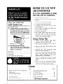
BEFORE YOU USE YOUR
AIR CONDITIONER
It is your responsibility to make
sure that your air conditioner:
Has been properly
l
Is the right
to cool.
l
installed.
size for
the area you
Copy your Model and
Serial Numbers here.. .
l
Is properly
connected
to electricity.
l
Is properly
electrically
grounded.
When you need service or call with a question, have
this information ready:
l
1.
Complete Model and Serial Numbers. To
find Model and Serial Numbers remove the
front panel (see pages 15-16). The numbers
are located either on a plate attached to the
lower front of the unit or on a label attached
to the evaporator coil cover near the top of the
unit.
SERIAL LABEL
Is properly
used only
intended to do.
Is properly
l
L.
l
l
Model Number
l
Serial Number
Purchase Date
Service Company and Telephone
not
maintained.
Energy Saving Tips
l
Purchase date from sales slip.
Copy this information in the spaces below.
Keep this book, your warranty and sales slip
together in a handy place.
or anyone
Also, remove energy label and buy guide.
Use damp cloth to take off any glue
residue. Do not use a sharp instrument
or any harsh or abrasive cleaners.
l
l
SERIAL PLATE
for the job it was
Is not used by children
able to operate it properly.
l
want
Number
Improve
windows,
home
insulation
and close fireplace
(seal
flue).
Close blinds or drapes on sunny
house; add window awnings.
Keep air filter clean. Don’t
with drapes or furniture.
doors,
side of
block air flow
Ventilate
attic
(high temperature
add to normal cooling load).
levels
Try not to use heat producing appliances
during the hottest part of the day. Turn
other
and
televisions,
radios,
lights,
appliances off when not needed.
0 Keep heat registers and cool air returns
closed or blocked off so cooled air won’t
escape.
l
Use a vent fan in areas where cooking,
laundry,
or bathing is done to pull out
extra heat and moisture near its source.
Contents
page
page
Before You Use Your Air Conditioner
Energy Tips ........................
...............
Electrical Requirements
.
. 2
2
3
7
...............
Installation
Instructions
How to Start and
Use Your Air Conditioner
. . . . . . . . . . 14
2
Cleaning and Caring for Your
....................
Air Conditioner
Cooling Load Guide .................
Self-Service Checklist ................
.................
Service Information
01986
Whirlpool
Corporation
16
18
19
19
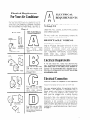
Electrical Requirements
For Your Air Conditioner
BELOW ARE ELECTRICAL
PLUGVARIATIONS.CHOOSE
THE ONE WHICH
MATCHES
THE AMPERE
RATING
OF
YOUR
UNIT.
THE NUMBER
OF AMPERES
IS PRINTED
ON THE SERIAL
PLATE, ATTACHED
TO THE FRONT
OF
THE UNIT, BEHIND
THE FRONT
PANEL
(SEE PAGE 2).
Chart-A
PLUG TYPE
3-PRONG
GROUNDING
PLUG
3-‘PRONG
GROUNDING
TYPE WALL
RECEPTACLE
POWER
SUPPLY
CORD
SEE ELECTRICAL
REQUIREMENTS
n
A
For 115 volt models
with
serial
plate
amperes of 7.6 through
12.0
D
D
B
For 230 volt and 230/
208 volt models with
serial plate amperes up
-through 12.0
CE
FoIr 230 volt and 2301
208 volt models with
serial
plate
amperes
up through 16.0
D
For 230 volt and 230/
208 volt models with
serial plate amperes up
through 24.0
n
A
ELECTRICAL
REQUIREMENTS
For 115 volt models with serial plate amperes of
7.6 through 12.0
OBSERVE ALL LOCAL
AND ORDINANCES
GOVERNING
Do not, under any circumstances,
power supply cord ground prong,
CODES
remove the
RECEPTACLE WIRING
RECEPTACLE
WIRING
should be at least as
large as 14 gauge. Use copper wire only. It is the
personal responsibility
and obligation
of the
customer
to provide
proper
and adequate
receptacle wiring installed by a qualified electrician. OBSERVE
NATIONAL
ELECTRICAL
CODE
AND
ALL
LOCAL
GOVERNING
CODES AND ORDINANCES.
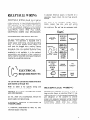
Electrical Requirements
A 115 volt (103.5 min., 126.5 max.) 60 hertz AC
only, 15 ampere fused electrical supply is required
(time delay fuse or time delay circuit breaker required). It is recommended that a separate circuit,
serving only this appliance, be provided. Do not use
an extension cord.
Electrical Connection
Electrical
Ground
RECOMMENDED
is Required
GROUNDING
on this Appliance
METHOD
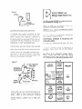
For your personal safety, this appliance must be
grounded.
This appliance
is equipped
with a
power supply cord having a 3-prong grounding
plug. To minimize
possible shock hazard, the
cord must be plugged into a mating 3-prong
grounding
type wall receptacle, grounded
in
accordance with the National
Electrical
Code
and local codes and ordinances. If a mating wall
receptacle is not available, it is the personal
responsibility
and obligation
of the customer to
have a properly grounded 3-prong wall receptacle
installed by a qualified electrician. See Figure 1
on page 4..
Figure 1
3-PRONG
GROUNDING
ELECTRICAL
REQUIREMENTS
PLUG
For 230 volt and 230/208 volt models with serial
plate amperes up through 12.0
‘ACLE
POWER-SUPPLY
ALTERNATE
Refer to Chart B
receptacle information
CORD
GROUNDING
METHOD
If changing and properly
grounding
the wall
receptacle is impossible and where local codes
permit
(consult
your electrical
inspector),
a
temporary
adapter may be plugged into the
existing 2-prong wall receptacie to mate with the
3-prong power supply cord. See Figure 2. THIS,
HOWEVER, IS NOT RECOMMENDED.
If this is done, you must connect the grounded
eyelet on the adapter to the wall receptacle
cover plate screw and from this same screw, you
must connect a separate copper ground wire
(~14 minimum) to a grounded cold water pipe.’
See Figure 2. Do not ground to a gas supply
pipe. Do not connect to electrical supply until
appliance is permanently
grounded.
OBSERVE ALL LOCAL
AND ORDINANCES.
GOVERNING
ELECTRICAL
GROUND
THIS APPLIANCE.
A three-wire,
single-phase
electrical supply is required.
and
CODES
remove the
IS REQUIRED
60 hertz
ON
AC only
A separate electrical
supply is required on a
separately fused circuit.
Do not fuse groundneutral.
See Chart B for receptacle voltage requireproper
fuse size, wire and wiring
ments,
connections
which must conform with rating
of the appliance. Do not use an extension cord.
Chart-B
GROUND ASSEMBLY
(ATTACH TO GROUNDED.
RECEPTACLE
VOLTAGE
(60 HERTZ
AC IN ALL
INSTANCES)
PLUG AND
RECEPTACLE
DATA
a
1’ -co\i
UP
through
12.0
MODEL WITH
SERIAL PLATE
OF 230/209
VOLTS
(197.6 MIN253 MAX.)
WhLL
RECEPTACLE
POWER SUPPLY CORD
*Cold water pipe must have metal continuity
to
electrical
ground and not be interrupted
by
plastic, rubber or other electrically
insulating
connectors
(including
water meter or pump)
without
adding a jumper wire at these connections.
SERIAL PLATE
AMPERES
MODEL WITH
SERIAL PLATE
OF 230 VOLTS
(207 MIN.253
MAX.)
AECEPTACLE
3-PRONG
GROUNDING
PLUG
wiring
Do not, under any circumstances,
power supply cord ground plug.
Figure 2
ELECTRICALLY
/ \
GROUNDED METAL
for specific
to be used.
I
RATING IN
AMPS
SEE BELOW
I
I
RECEPTACLE WIRING
RECEPTACLE
WIRING
should be at least as
large as size shown on electrical Chart B. Use
copper wire only. It is the personal responsibility
and obligation
of the customer
to provide
proper and adequate receptacle wiring installed
by a qualified electrician. OBSERVE NATIONAL
ELECTRICAL
CODE
AND
ALL
LOCAL
GOVERNING
CODES AND ORDINANCES.
RECOMMENDED
GROUNDING
METHOD
For your personal safety, this appliance must be
grounded.
This appliance
is equipped
with a
power supply cord having a 3-prong grounding
plug. To minimize
possible shock hazard, the
cord must be plugged into a mating 3-prong
grounding
type wall receptacle, grounded
in
accordance with the National
Electrical
Code
and local codes and ordinances. If a mating wall
receptacle is not available, it is the personal
responsibility
and obligation
of the customer to
have a properly grounded 3-prong wall receptacle
installed by a qualified electrician.
f?
ELECTRICAL
REQUIREMENTS
L&7
A separate electrical
supply is required on a
separately
fused circuit.
Do not fuse groundneutral.
See Chart C for receptacle voltage requirements,
proper
fuse size, wire and wiring
connections which must conform with rating of
the appliance. Do not use an extension cord.
Chart-C
PLUG AND
RECEPTACLE
DATA
RECEPTACLE
SERIAL PLATE
AMPERES
MODEL WITH
SERIAL PLATE
OF 230 VOLTS
(207 MIN,253
MAX.)
I
MoDEL
SERIAL PLATE
OF 2301208
VOLTS
(197.6 MN
253 MAX,)
USE TIME-DELAY
FUSE
OR TIME
DELAY CIRCUIT
BREAKER
RATING IN
AMPS
UP
through
16.0
I
I
TYPE
OF BRANCH
CIRCUIT
MINIMUM
RECEPTACLE
WIRE SIZE
12 GAUGE
SINGLE
OUTLET
ONLY
USE COPPER
WIRE ONLY
I
For 230 volt and 230/208 volt models with serial
plate amperes up through 16.0
Refer to Chart C
receptacle information
for specific
to be used.
OBSERVE ALL LOCAL
AND ORDINANCES.
wiring
GOVERNING
Do not, under any circumstances,
power supply cord ground plug.
and
CODES
remove the
ELECTRICAL
GROUND
THIS APPLIANCE.
IS REQUIRED
A three-wire,
single-phase
electrical supply is required.
60 hertz
AC
ON
only
RECEPTACLE WIRING
RECEPTACLE
WIRING
should be at least as
large as size shown on electrical Chart C. Use
copper wire only. It is the personal responsibility
and obligation
of the customer
to provide
proper and adequate receptacle wiring installed
by aqualified electrician. OBSERVE NATIONAL
ELECTRICAL
CODE
AND
ALL
LOCAL
GOVERNING
CODES AND ORDINANCES.
RECOMMENDED
GROUNDING
METHOD
Chart-D
For your personal safety, this appliance must be
grounded.
This appliance is equipped
with a
power supply cord having a 3-prong grounding
plug. To minimize
possible shock hazard, the
cord must be plugged into a mating 3-prong
grounding
type wall receptacle, grounded
in
accordance with the National
Electrical
Code
and local codes and ordinances. If a mating wall
receptacle is not available, it is the personal
responsibility
and obligation of the customer to
have a properly grounded 3-prong wall receptacle
installed by a qualified electrician.
Refer to Chart D
receptacle information
for specific
to be used.
OBSERVE ALL LOCAL
AND ORDINANCES.
wiring
_
with
RECEPTACLE
VOLTAGE
(60 HERTZ
AC IN ALL
INSTANCES)
SERIAL PLATE
AMPERES
MODEL WITH
SERIAL PLATE
OF 230 VOLTS
(207 MIN,253
MAX.)
1
MODEL WITH
SERIAL PLATE
OF 2301209
VOLTS
(197.6 MIN253 MAX.)
CART.
TYPE
ONLY
MINIMUM
RECEPTACLE
WIRE SIZE
“P
through
24.0
TYPE
OF BRANCH
CIRCUIT
SEE BELOW
10 GAUGE
USE COPPER
WIRE ONLY
SINGLE
OUTLET
ONLY
and
RECEPTACLE WIRING
GOVERNING
Do not, under any circumstances,
power supply cord ground plug.
RECEPTACLE
USE TIME-DELAY
FUSE
OR TIME
DELAY CIRCUIT
BREAKER
RATING IN
AMPS
ELECTRICAL
REQUIREMENTS
For 230 volt and 230/208 volt models
serial plate amperes up through 24.0
PLUG AND
RECEPTACLE
DATA
CODES
remove the
ELECTRICAL
GROUND
THIS APPLIANCE.
IS REQUIRED
A three-wire,
single-phase
electrical supply is required.
60 hertz
AC
RECEPTACLE
WIRING should be at least as
large as size shown on electrical Chart D. Use
copper wire only. It is the personal responsibility
and obligation
of the customer
to provide
proper and adequate receptacle wiring installed
by a qualified electrician.OBSERVE
NATIONAL
ELECTRICAL
CODE
A:\ID
ALL
LOCAL
GOVERNING
CODES AND ORDINANCES.
ON
only
A separate electrical
supply is required on a
separately fused circuit.
Do not fuse groundneutral.
See Chart D for receptacle voltage requirements,
proper
fuse size, wire and wiring
connections which must conform with rating of
the appliance. Do not use an extension cord.
RECOMMENDED
GROUNDING
METHOD
For your personal safety, this appliance must be
grounded.
This appliance
is equipped
with a
power supply cord having a 3-prong grounding
plug. To minimize
possible shock hazard, the
cord must be plugged into a mating 3-prong
grounding
type wall receptacle, grounded
in
accordance with the National
Electrical
Code
and local codes and ordinances. If a mating wall
receptacle is not available, it is the personal
responsibility
and obligation
of the customer to
have a properly grounded 3-prong wall receptacle
installed by a qualified electrician.
INSTALLATION INSTRUCTIONS
for Your Air Conditioner
-ORfor Through-The-Wall
installation,
follow:
INSTALLATION
INSTRUCTION
2
(on page 12).
If you have these parts,
follow:
INSTALLATION
INSTRUCTION
1
(below).
u
Installation
Instructions
1
l
Unpack accessory
fore installing your
installation
can be
a drill, saw, small
socket wrench, l/8”
WINDOW
parts (see Figure 3) beair conditioner.
A normal
made with a screwdriver,
level, pocket knife, 7/16”
drill bit and tape measure.
LOCK
WE”
WIDE)
CAUTION:
l
l
l
Be sure air conditioner
does not fall out of
window during installation.
Handle
the air conditioner
with
care.
Watch out for the sharp metal fins on
the front and rear coils.
Do not use the collected water for drinking
purposes. It is not sanitary.
4 SHEET
METAL
SCREWS
(#8X3/8”
ROUND
HEAD)
2
7 SHEET
METAL
SCREWS
(rlOX112”
HEX HEAD)
3Wb
SCREWS
(qloX3/4”
ROUND HEAD)
u
5 FLAT
WASHERS
6 NUTS
. Pick the right window.
First, decide what
room(s) you want to cool. Then choose a
window that will allow the air-conditioned
air
to flow freely and directly into the room(s)
you want cooled. Remember, it’s difficult
to
7
move air around corners. Choose a window
that’s also near an electrical outlet. (Refer
to the ELECTRICAL
REQUIREMENT
pages
for type of receptacle and wiring needed.) Do
not use an extension
cord. The window in
which you place your air conditioner
should
have an opening of at least 26 inches in width
and at least 20 inches in height (see Figure 4).
Standard installation
parts are supplied for
double-hung sash windows up to 54 inches in
width.
Figure 4
3
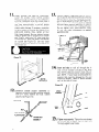
l
5.
Attach seal strips to cabinet. Place 3/8” wide
self-adhering seal strip on window side of bottom flange. Now, starting at the lower corner
of the cabinet, apply 3/8”-wide
seal strips
over the center line of the pre-drilled holes for
one of the side mounting
angles, over the
center line of pre-drilled
holes for the top
mounting channel, and over the center line of
pre-drilled
holes for the other side mounting
angle. (See Figure 7.)
Figure 7
Remove front panel by pushing it down and
pulling toward you (see Figure 5). This protects the panel from damage and makes the
air conditioner
easier to handle
during
installation.
6
l
Slide unit out of cabinet. First, disconnect the
green ground wire at the left-front
corner of
base of unit by removing retaining screw (save
screw for reuse later). Now slide unit out of
cabinet by pulling out on handle on bottom
(see Figure 6).
GROUND WIRE SCREW -
b
.HANDLE
Attach side mounting angles to the sides of
the cabinet by using four hex-head sheet metal
screws (see Figure 8). Punch holes in seal
strip before driving screws. Be sure flange of
each side mounting
angle faces inside. Now
attach top mounting angle to cabinet by using
three hex-head sheet metal screws. Again, be
sure flange is facing inside.
Figure 8
7
l
Measure and cut filler board to proper sizes.
First, measure the distance
from inside one
window channel to the inside of the other
channel and subtract l/4”. Now subtract the
width of the air conditioner
and divide by 2
(see Figure 9). This will give you the width to
cut each filler board. Be sure to cut the filler
board across the mid-section
of its longest
measurement. Because the filler boards will be
equal in width, they will automatically
center
your conditioner
in your window.
9
l
Place window gasket over top mounting angle
and filler boards (see Figure 11). First, measure depth of window channel. Cut notch on
end of window gasket to same depth. Next,
measure window
width
between
window
channels
(include
full
depth of window
channels). Now cut gasket to proper length.
Cut unnotched
end of gasket to match the
notched end. Place gasket long groove over
top mounting angle; place short rear groove
over filler boards with long side facing inside.
Figure 9
Figure 11
FILLER BOARD HERE
MEASURE DISTANCE FROM INSIDE
ONE WINDOW CHANNEL TO INSIDE
OF THE OTHER AND SUBTRACT 114” 1
TOP ANGLE HERE
1
DEPTH OF WINDOW
CHANNEL
8
. Apply seal strips and attach filler boards. Determine which will be your left and right filler
boards. The holes on each board should align
with the holes in the side mounting angles.
Each filler board should also extend about
l/2” above the top edge of the air conditioner
cabinet. Now apply 3/8”-wide
seal strips on
the room side of each filler board as shown in
Figure 10 (i.e. along the bottom edge and
window channel edge). Now attach the filler
boards to the side mounting angles with four,
3/8”,
round-headed
sheet metal
screws.
Tiqhten the screws only loosely, so the filler
boards can be moved back and forth.
Figure 10
10
l
Place cabinet in window by turning cabinet to
one side to get one filler board into window
channel. Now maneuver other filler board into
window
channel (see Figure 12). Reaching
through window
opening, push filler boards
from outside as far toward you as they will
go. Be sure to use the foam blocks that are
provided.
Figure 12
THE FOAM BLOCKS PROVIDED
ARE TO HOLD FILLER BOARD TIGHT
AGAINST WINDOW CHANNEL. CUT
BLOCKS 114 INCH WIDER THAN
CHANNEL AND WEDGE INTO PLACE.
FRONT
9
11
Lower window
and level air conditioner.
Lower the window
firmly
behind window
gasket. Leveling the cabinet is not required in
a normal installation
since the proper slope is
designed into the product. However, be sure
you have approximately
a one-half bubble
(5/8”)
downward
tilt to the outside for
proper water drainage. If necessary, reposition
or shim cabinet to provide the proper tilt or
side-to-side
leveling.
Now, tighten all four
filler board screws. Be sure cabinet bottom
flange is against rear of window sill for proper
seal. Finally, make two l/8” pilot holes into
the window sill, using the holes in the cabinet
as a guide (see Figure 13). Use two wood
screws to secure the bottom of the cabinet to
the window sill.
l
13
Position support assemblies against bottom
rail of cabinet and slide toward house, allowing
approximately
one-inch
clearance between
end of angle support and wall (see Figure 15).
Select proper sets of square holes in cabinet
rails and fasten support assemblies to cabinet
rails by using 3/4” bolts, washers and nuts.
Do not tighten nuts. Leave assembly loose,
to support
so you can make adjustments
assemblies later.
l
14
. Insert end tabs on wall rail through slot in
each support assembly (see Figure 16). Slide
each support assembly toward house. Be sure
wall rail is positioned
firmly against exterior
wall. NOTE: If your house is constructed of a
material that could be damaged by the wall
mounting
support,
fasten a board between
wall rail and side of house.
12
. Construct
outside
support
assemblies
by
fastening vertical and angle supports together
with 3/4” bolts, washers and nuts. Tighten
securely (see Figure 14).
PLAIN WASHER
FASTEN BOLT
SECURELY
10
. Tighten nuts securely. Tighten the nuts closest
to the wall last to assure that the wall rails
fit snugly against your house.
16
. Install window
rail seal and window
lock
bracket and drain cup. Press foam meeting rail
seal into place and cut to proper length (see
Figure 17.) Make a mark and drill a l/8” pilot
hole, then install lock bracket using wood
screw.
Seal small openings
gum-type sealer.
Figure 17
n
around
installation
18
l
with
NOTE: During high
humidity, condensate
may drip from the
outside of your air
conditioner onto the
ground below. If your
air conditioner
is installed
where this Is undesirable,
you can direct the water
to a more suitable spot
by using some flashing
or other similar means.
Insert air conditioner
into cabinet. Slide air
conditioner
only three-fourths
of the way
into the cabinet. Do not push against sharp
fins and plastic parts. Apply 5/8”-thick
seal
strip onto bottom of base of air conditioner
as shown in Figure 19. Now push air conditioner all the way into cabinet being sure
angle bracket on base clears bottom front
edge of cabinet. Again, do not push against
sharp fins and plastic parts. Attach green
ground wire to the left-front
corner of unit
base by using ground wire screw (see Figure
19).
Figure 19
DRAIN CUP ASSEMBLY
FLANGE
SEAL
INSERT INTO
ABINET RAIL
SLOT.
17
l
Apply seal strip to top of unit flange as shown
in figure 18. Plug two crating bolt holes (l/4”
diameter with gum sealer to prevent water
dripping from these holes (see Figure 18.)
GROUND
WIRE
ANGLE BRACKET
ON BASE
Figure 18
CRATING
BOLT HOLE
19
l
Attach front panel by placing bottom edge on
clips and pushing top down, then in and up.
1
l
Through-the-wall
Installation Instructions
. . . for slide out chassis model only.
2
l
Pick the right wall. First, decide what room(s)
you want to cool. Then choose a wall that
will allow the air-conditioned
air to flow
freely and directly into the room(s) you want
cooled. Remember, it’s difficult
to move air
around corners. Choose a location that’s also
near an electrical outlet. (Refer to the ELECTRICAL
REQUIREMENT
pages for type of
receptacle and wiring needed.) Do not use an
extension cord. (CAUTION: DO NOT LOCATE
AIR
CONDITIONER
WHERE
PLASTIC
CABINET
FRONT WILL BE EXPOSED TO
A HEAT
SOURCE
THAT
RAISES THE
SURFACE
TEMPERATURE
IN EXCESS
OF 120” F.)
Choose the type of decorative molding you
want to use around the room side of the cabinet. Your choice affects the finish frame
alignment with the inside wall. When using a
wood, metal or plastic molding, the finish
frame should almost line up with the inside
wall. If the wall is plastered to the cabinet
and no molding is used, the finish frame must
be set into the wall by l/2” (see Figure 20 for
frame construction
or Figure 21 for brick
veneer construction).
Cut through two studs
for support.
CAUTION:
l
l
l
Be sure air conditioner
installation.
does not fall during
Handle
the air conditioner
with
care.
Watch out for the sharp metal fins on
the front and rear coils.
Do not use the collected water for drinking
purposes. It is not sanitary.
3
l
Provide an opening through the wall for a
finish frame. Observe all local governing codes
and ordinances. For wall opening dimensions,
use those shown in Figure 22 and add wood
frame thickness (use 1” lumber or heavier).
When determining
finish
frame thickness,
be sure you do not cover side cabinet louvers.
A 4” minimum clearance between side cabinet
louvers and adjoining wall allows for proper
airflow into air conditioner.
unit base by using retainer screw. (CAUTION:
KEEP
WIRE
CONNECTED
WHENEVER
AIR CONDITIONER
IS IN CABINET.
IT IS
THERE FOR YOUR ELECTRICAL
SAFETY
DURING OPERATING AND MAINTENANCE.)
12
l
13
Attach
front
panel. Place top in position
first and push to engage clips. Then engage
clips near bottom of sides. Clips go inside
cabinet flange (see Figure 23).
l
40
Construct
something
surface.
5a
The front, escutcheon plate and knobs are
packaged separately. This protects the plastic
front from damage and makes the air conditioner easier to handle during installation.
l
8
l
Slide unit out of cabinet. First, disconnect the
green ground wire at the left-front
corner of
base of unit by removing retaining screw (save
screw for reuse later). Now slide unit out of
cabinet by pulling on handle at bottom. (See
Page 8, Figure 6.)
Insert exterior cabinet through wall opening.
Leave %” minimum
overhang into the room
at top of cabinet, after allowing for trim. For
proper
outward
water drainage,
shim or
reposition
cabinet
to provide
the proper
downward tilt to the outside (% bubble or 1”)
and side-to-side leveling.
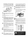
9a
10
l
11
l
finish frame. Apply creosote or
equal to the outside
exposed
Install the finish frame in the wall opening.
Square and level frame and nail it securely to
the studs.
6
70
Place escutcheon plate into position.
Insert
knobs through
holes and press them onto
shafts (see Figure 23).
Fill all spaces between
frame with insulation.
cabinet
14
15
l
Caulk all outside wall openings around cabinet.
. If needed, install molding around room side of
cabinet. OPTIONAL:
During high humidity,
condensate may drip from the outside of your
air conditioner
onto the ground below. If
your air conditioner
is installed where this is
undesirable,
you can direct the water to a
more suitable spot by simply attaching
a
5/8-inch inside-diameter,
thin-walled
hose to
the drain spout at rear of cabinet (see Figure 24).
Figure 24
and finish
Drill holes in the cabinet and attach it securely
to finish frame. Use ten #lO x 1” wood
screws (four screws for each side and two
screws for the top; not included).
Do not
overtighten
screws or cabinet will distort and
provide a poor air seal between cabinet and
unit.
Insert air conditioner
into cabinet. Do not
push against sharp fins and plastic parts. Attach
green ground wire to the left-front
corner of
13
HOW TO STA 3T AND USE
YOUR AIR C(: NDITIONER
FRESH AIR AND
EXHAUST CONTROL
ENERGY SAVER
CONTROL
Be sure air conditioner
is OFF
before
plugging
it in.
To Start Your Air Conditioner
Using the Energy SaverControl
1
2
(for Energy Saver models only).
Set exhaust
cooling.
l
control
to OFF
for
maximum
1
l
Choose either LO COOL,
COOL fan speed setting.
l
LO COOL . . .
MED COOL
HI COOL
.
MED COOL OR HI
for sleeping comfort
2
l
. . . , . . . , , for normal cooling
. . . . . . . for maximum
cooling
Choose a fan setting:
NORM FAN.
either
AUTO
FAN or
The AUTO FAN setting saves energy. The fan
will cycle on and off as the thermostat turns
the compressor on and off. This saves the cost
of electrical energy that would be used to run
the fan continuously.
It is normal for the fan to turn on and off in
the AUTO FAN setting. The amount of time
the unit will be off depends on room temperature and thermostat
setting.
3
14
l
to Number 6
(midsetting). You can adjust the air conditioner’s cooling performance by resetting the
thermostat control to a higher number for
maximum cooling. Lower the number setting
to less cooling. You will need to experiment
to find the setting which suits vou best.
Turn
thermostat
control
3
. In NORM FAN setting, the fan runs all the
time even though the thermostat will turn the
compressor
on and off. Use NORM FAN
during extremely warm or humid weather and
for rooms that need to be cooled constantly.
Using the Fresh Air and
Exhaust Control
This control setting draws stale or smoky air
from the room. It can also draw fresh air from
the outside into the room.
1
.
2
l
1.
To exhaust room air
Move the tabs at the
bottom
of the
grille to the right, left or straight ahead.
Simply move the levers in the direction you
want the air to go (see Figure 25).
On some models, air flow can be directed up
or down. Move the tab in the center louver to
direct air.
Set exhaust control
to EXHAUST. Set fan
control to speed desired.
Set fan control to
FAN ONLY if no cooling is
desired.
20To
bring in outside air
Set fresh air and exhaust
control to FRESH AIR.
Set fan control to
FAN ONLY.
3.
Cleaning and Caring For Your
Air Conditioner
Proper use and care of your air conditioner
will
help insure longer life and lower operating costs.
Follow
these instructions
carefully.
Call your
dealer for an annual checkup.
Cleaning of Front Panel
To circulate room air
Set fresh air and exhaust
control to OFF. Set
fan control to
FAN ONLY.
If the front panel of your unit looks like the
one shown in Figure 26, follow these instructions.
1
Remove the front
panel from unit when
cleaning.
Press down at top edge of the
front as shown in Figure 26.
l
Changing Air Direction
The louvers in the grille area at the top of the air
conditioner
control the direction of the cooled air.
2
3
l
l
When the front moves away from
cabinet, pull top of front toward you.
Lift up and away
clips.
from
the bottom
top
of
spring
15
Cleaning Air Conditioner Filter
The filter is cleanable. A clean filter helps
remove dust, lint and other particles from the
air. Check every two weeks to see if filter
needs cleaning.
1a
If the front panel of your unit looks like the
one shown in Figure 26, remove filter from
plastic front frame, by removing elastic band
which holds it in place (see Figure 28).
Figure 28
5
4
5
l
l
Clean front panel with warm water and mild
soap or detergent. Use a soft cloth. Rinse and
dry. Replace front panel.
Wipe control
panel clean with a soft dry cloth.
If the front panel of your unit looks like the
one shown in Figure 27, follow these instructions.
2
l
First, pull top of panel away from unit
to disconnect
from top clips. Then disconnect
panel from bottom
clips. Pull
panel straight away from panel.
If the front panel of your unit looks like the
one shown in Figure 27, flex middle of filter
out until the frame clears the tabs (circled)
as shown in Figure 29.
Figure 29
Clean front panel with warm water and
mild soap or detergent. Use a soft cloth.
Rinse and dry. Replace front panel.
Wipe control
cloth.
-
panel clean with
a soft dry
27
\ Figure
3
.
Clean filter,
using a vacuum cleaner.
-OR-
4
16
l
If very dirty, wash filter with warm water
and mild
detergent.
Air dry thoroughly
before replacing.
Annual Maintenance for Your
Air Conditioner
Your air conditioner
help insure steady,
the year.
needs annual maintenance to
top performance
throughout
Call the service company recommended
by your
dealer to:
l
Inspect and clean the coils and condensate
water passages.
l
Check fan and oil the fan motor.
l
The compressor
Expense of annual
responsibility.
NOTE: It’s a good idea to wait 24 hours
before starting the unit again. This allows
time for all areas to dry out. The water from
rainfall or from normal operation
does not
harm these components.
Oiling of the Fan Motor
is sealed and needs no oiling.
inspection
is customer’s
- or If you are familiar with electrical appliances,
you can do the cleaning and maintenance
yourself.
If you decide to go ahead, follow
these steps:
1
Oil the fan motor per instructions
on the
motor. To add oil, pull out the oil hole plug
at each end of the motor. (See Figure 30.)
l
Figure 30
1
l
2
l
3
l
4
l
OIL PLUGS
REMOVE UNIT FROM CABINET.
Wrap the
motor, electrical control box and electrical
terminals box in plastic film and make sure no
water or other liquid
gets inside any of
these parts. It should damage the insulation
and cause serious trouble.
Carefully
clean and hose out the base, coils
and condensate pans. Clean at least once a
year or more often if the condenser coils and
pans collect
dirt, sand, leaves, insects or
algae. Also, clean if you detect an odor from
the air conditioner.
While the cabinet is open,
this is a good time to oil the fan motor.
2
l
An easy to use one-ounce capsule of especially
recommended
oil (Part No. 10943) can be
ordered from your dealer.
Replace the plug to keep dirt
bearings.
3
l
from
motor
Reinstall the unit in cabinet after performing
maintenance.
(See Installation
Instructions.)
Remove plastic film from motor and electrical
parts.
Replace unit in cabinet.
17
COOLING
LOAD GUIDE-SQUARE
FEET METHOD
ROOM AIR CONDITIONERS
To make sure you choose
METHOD
the right size unit, use IhIs “COOLING
LOAD GUIDE SQUARE FEET
It IS a quick, easy means of computing
capacity
For exiremes III exposure. shadtng. lnsulallon and bwldtng consln~ct~on AHAM Cooling Load Esllmale Form RAC~I must be used
,,
,
/
I’A,.
COOLINGCAPACITYREQUIRED--BTU/HR
INSTRUCTIONS:
1. Determine the area to be cooled in sauare feel and locate thal
point on the left side of chart
2. Move honzonlally
across lo the center line of Band A B or C
according
to the condillon
of the ceiling in the area to be cooled
Band A-Occupied
Space Above Celling
Band B-lnsulaled
Celling Under Alhc
Bmnd C-Non-Insulated
Celling Unaer Attic
3. From center of band move wthln the band to left for more
northerly exposure or rlght for more westerly exposure
4. From lhls point, read down lo bottom of chart to determlne
required
Btulhr output
Wrlle Ihe Bluihr figure I” the space
Indicated below
5.6.
Btuihr
(from number
4 above)
Locale your geographic
area on unset map and multiply
factor shown by flqure in number 5
If room air condltloner
IS lnlended prlmarlly for nighttime cool~no sublracl 30% (from flaure I” number 6)
Subtract 36 Btu/hr from figure In-number
7 (or 6) for
6.
each linear fool of wall separallng
the area lo be cooled
from another cooled room
9.--~
If more than two people occupy area. add 600 Btufhr per
person (to figure I” number 8). If orlly one person.
subtract 600 Btuihr
10.
~ Add 4000 Bluihr (lo figure in number 9) 11 area to be
cooled Includes kitchen
For best results, a room condltlonlng
unit or units with a cooling
capacity rating close to that estimated above should be selected
A smaller capacity un11 operahng
continuously
~111 contnbule
more to comfort
than a larger capacity unit operating
Intermitlently
7.
18
AHAiL
Room Air Conditioner
MAP FACTORS
If you needserviceor
assistance,we suggestyou
follow thesefour steps:
1. Before calling for assistance
3. If you need service Whirlpool
Performance problems often result from little things
you can find and fix yourself without tools of any
kind.
Unit won’t run:
1,
2.
3.
4.
5.
7ma%l~E
Is unit plugged in?
Is switch ON?
Is thermostat
set too WARM?
Is time-delay
fuse blown?
Has local power failed?
Unit blows fuses:
1. Are time-delay
fuses used?
2. Is an extension
cord being used? (Do not use.)
waiting
two minutes
after turning
3. Are you
circuit off before trying to restart unit?
has a nationwide net work of franchaised TECH-CARE@
Companies.
service
service
TECH-CARE
technicians are trained
to fulfill
the product
warranty
and
provide
FRANCHISED
SERVICE
after-warranty
service,
anywhere in the United States. To locate TECHCARE service in your area, call our COOL-LINE
service assistance telephone number (see Step 2) or
look in your telephone
directory
Yellow Pages
under:
cooling
Unit turns on and off, or does not cool room:
1. Is filter clean?
2. Are coils clean?
Both
evaporator
(inside)
and condenser (outside)?
3. Is there excessive moisture or heat? (Open vessel cooking,
showers, etc.)
4. Set fan to higher speed.
5. Set thermostat
to a cooler setting.
Operating sounds:
1. When your room air conditioner
is operating normally,
you will hear sounds such as:
l
Droplets
of water hitting
the condenser,
causing a
“pinging”
or “clicking”
sound. Water droplets
help
to cool the condenser.
l
Air movement
from the fan, especially
on high fan
speed setting.
l
Clicks from thermostat
cycle.
2. Sounds also may be caused by house construction
such as vibration
of the unit due to wall construction
or unsteady window
mounting
area.
2. If you need assistance
Call the Whirlpool COOL-LINE@ service assistance
telephone number. Dial free from:
Continental
U.S. . . . . . . . . . (800) 253-1301
Michigan . . . . . . . . . . . . . . . (800) 632-2243
Alaska & Hawaii . . . . . . . . . (800) 253-l 121
and talk with one of our trained Consultants. The
Consultant can instruct you in how to obtain satisfactory operation from your appliance or, if service is necessary, recommend a qualified
service
company in your area.
APPLIANCES-HOUSEHOLDMAJOR-SERVICE
A REPAIR
ELECTRICAL
APPLIANCESMAJOR-REPAIRIWG
A PARTS
WHIRLPOOL APPLIANCES
WHIRLPOOL APPLIANCES
FRANCHISED TECH CARE SERYICE
OR FRANCHISED TECH CARE SERVICE
st::H L'ict
('0 \li' 1 \,t \
';ttii
/(‘t
f o\lP,\,t.~
IYZ SERVICE CO
XYZ SERVICE CO
I23 Maple
999 9959
123 MaDie
999 9999
OR
WASHING
MACHINES,
A IRONERS-SERVICING
DRYERS
FRANCHISED TECH CARE SERVICE
c 0 \,i' 1 \,t \
.< t I! il(‘i
XYZ SERVICE CO
999 9999
123 Maple
4. If you have a problem
Call our COOL-LINE service assistance telephone
number (see Step 2) and talk with one of our
Consultants, or if you prefer, write to:
Mr. Robert Stanley
Division Vice President
Whirlpool Corporation
2000 US-33 North
Benton Harbor, MI 49022
If you must call or write, please provide: model
number, serial number, date of purchase, and a
complete description of the problem. This information is needed in order to better respond to your
request for assistance.
FSP IS a registered trademark
of WhIrlpool Corporotlon for
quollh/ parts took for this
FSP
svmbo or qualIly whenever
you need a replacement
part
8
for your Whutpool appliance
FSF replacement
parts
WIII fit right and work nght because they are
made to the same exactng specifications
used to buld every new Whlrlp3o appliance
0
19