1
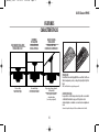
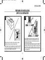
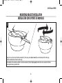
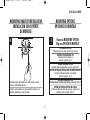
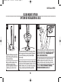
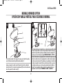
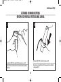
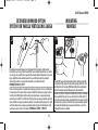
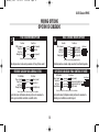
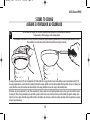
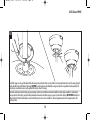
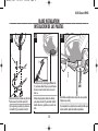
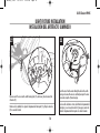
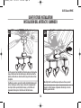
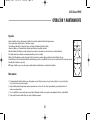
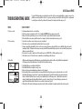
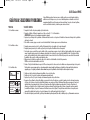
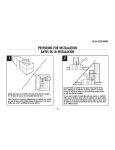
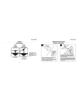
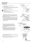
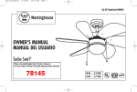
UL_Xavier_72265
12/13/05
9:18 AM
Page 1
UL-ES-Xavier-WH05
OWNER'S MANUAL
MANUAL DEL USUARIO
Xavier
TM
Please write model number here for future reference: /
Por favor, incluya el número del modelo aquí para futura referencia:
Net Weight: 17.18 LBS
Peso Neto: 7.81 KGS
MR
UL_Xavier_72265
12/13/05
9:18 AM
Page 2
UL-ES-Xavier-WH05
SAFETY TIPS
OBSERVE THE FOLLOWING: READ AND SAVE THESE INSTRUCTIONS
WARNING: TO REDUCE THE RISK OF FIRE, ELECTRIC SHOCK, OR PERSONAL INJURY, MOUNT TO OUTLET BOX MARKED "ACCEPTABLE FOR FAN SUPPORT",
AND USE THE OUTLET SCREWS PROVIDED WITH THE OUTLET BOX. MOST OUTLET BOXES COMMONLY USED FOR THE SUPPORT OF LIGHTING FIXTURES
ARE NOT ACCEPTABLE FOR FAN SUPPORT AND MAY NEED TO BE REPLACED. CONSULT A QUALIFIED ELECTRICIAN IF IN DOUBT.
1. Installation work and electrical wiring must be done by qualified person(s) in accordance with all applicable codes and standards (ANSI/NFPA 70-1996), including fire-rated construction.
2. Use this unit only in the manner intended by the manufacturer. If you have any questions contact the manufacturer.
3. After making the wire connections, the wires should be spread apart with the grounded conductor and the equipment-grounding conductor on one side of the outlet box and ungrounded conductor on
the other side of the outlet box.
4. Before you begin installing the fan, Switch power off at Service panel and lock service disconnecting means to prevent power from being switched on accidentally. When the service disconnecting
means cannot be locked, securely fasten a prominent warning device, such as a tag, to the service panel.
5. Be cautious! Read all instructions and safety information before installing your new fan. Review the accompanying assembly diagrams.
6. When cutting or drilling into wall or ceiling, do not damage electrical wiring and other hidden utilities.
7. Make sure the installation site you choose allows the fan blades to rotate without any obstructions. Allow a minimum clearance of 7 feet from the floor to the trailing edge of the blade.
8. To reduce the risk of fire, electric shock, or personal injury, this fan must be mounted to an outlet box marked suitable for fan support. And use mounting screws provided with the outlet box.
(Mounting must support at least 35 lbs.)
9. Do not bend blade holders during installation to motor, balancing or during cleaning. Do not insert foreign object between rotating blades.
10. Attach the mounting bracket using only the hardware supplied with the outlet box. Fan is only to be mounted to an outlet box marked “Acceptable for Fan Support”.
11. To reduce the risk of fire or electric shock, do not use this fan with any solid state fan speed control device, or variable speed control.
12. If this unit is to be installed over a tub or shower, it must be marked as appropriate for the application.
13. NEVER place a switch where it can be reached from a tub or shower.
14. The combustion airflow needed for safe operation of fuel-burning equipment may be affected by this unit’s operation. Follow the heating equipment manufacturer’s guideline safety standards such as
those published by the National Fire Protection Association (NFPA), and the American Society for Heating, Refrigeration and Air Conditioning Engineers (ASHRAE) and the local code authorities.
15. Before servicing or cleaning unit, Switch power off at Service panel and lock service disconnecting means to prevent power from being switched on accidentally. When the service disconnecting means
cannot be locked, securely fasten a prominent warning device, such as a tag, to the service panel.
Phillips Screwdriver
TOOLS REQUIRED
Wire Cutters
Pliers
2
Step Ladder
UL_Xavier_72265
12/13/05
9:18 AM
Page 3
UL-ES-Xavier-WH05
CONSEJOS DE SEGURIDAD
HAGA LO SIGUIENTE: LEA Y GUARDE ESTAS INSTRUCCIONES
ADVERTENCIA: PARA REDUCIR EL RIESGO DE INCENDIO, DESCARGA ELÉCTRICA O LESIONES PERSONALES, MONTE EL VENTILADOR EN UNA CAJA DE EMBUTIR ROTULADA “ADECUADA PARA
VENTILADORES”, Y UTILICE LOS TORNILLOS DE MONTAJE INCLUIDOS CON LA CAJA DE EMBUTIR. LA MAYORÍA DE LAS CAJAS DE EMBUTIR UTILIZADAS NORMALMENTE PARA ARTEFACTOS DE
ILUMINACIÓN NO SON ADECUADAS PARA VENTILADORES Y DEBERÍAN SER REEMPLAZADAS. SI TIENE PREGUNTAS, CONSULTE A UN ELECTRICISTA CERTIFICADO.
1. El trabajo de instalación y el cableado eléctrico los deben efectuar personas calificadas cumpliendo con todos los códigos y las normas aplicables (ANSI/NFPA 70-1996), incluyendo las de incendio.
2. Use esta unidad sólo de la manera en que el fabricante quiere que se haga. Si tiene dudas, llame al fabricante.
3. Después de hacer las conexiones, se deben separar los cables: el conductor de puesta a tierra y el conductor de puesta a tierra del equipo a un lado de la caja de embutir, y el conductor que no
tiene puesta a tierra del otro lado de la misma.
4. Antes de comenzar a instalar el ventilador, apague la alimentación en el panel de servicio y bloquee el medio de desconexión del servicio para evitar que se encienda accidentalmente.
Cuando no se puede bloquear el medio de desconexión del servicio eléctrico, fije de manera segura y un dispositivo de advertencia prominente, como un rótulo, al panel de servicio.
5. ¡Tenga cuidado! Lea todas las instrucciones y la información de seguridad antes de instalar su ventilador nuevo. Revise los diagramas de montaje incluidos.
6. Al cortar o perforar una pared o el cielo raso, no dañe el cableado eléctrico y otras instalaciones de servicios públicos ocultos.
7. Asegúrese de que el sitio para la instalación que escoja permita que el ventilador gire libremente sin obstrucciones. Deje un espacio mínimo de 7 pies desde le piso hasta el borde posterior de la paleta.
8. Para reducir el riesgo de incendios, choques eléctricos o lesiones personales, este ventilador se debe montar sobre una caja de embutir que tenga una marca que indique que es adecuada para
soportar un ventilador. Además debe utilizar los tornillos correspondientes incluidos con la caja de embutir. (El montaje debe soportar por lo menos 35 libras)
9. No doble los soportes para las paletas durante la instalación al motor, al balancear o durante la limpieza. No inserte objetos extraños entre las paletas mientras giran.
10. Fije el soporte de montaje usando sólo la tornillería suministrada con la caja de embutir. El ventilador sólo se debe montar en una caja de embutir marcada “Acceptable for Fan Support”
(Aceptable para soportar ventiladores).
11. Para reducir el riesgo de incendios o choques eléctricos, no use este ventilador con un dispositivo de control de velocidad de estado sólido para ventilador, o un control de velocidad variable.
12. Si esta unidad se instalará sobre una bañera o una ducha, debe estar identificada como adecuada para ese tipo de aplicación.
13. NUNCA coloque un interruptor donde se pueda alcanzar desde una bañera o una ducha.
14. Es posible que la operación de esta unidad afecte el flujo de aire de combustión necesario para la operación segura de equipo que quema combustible. Siga la directrices de seguridad del fabricante
de equipo de calefacción como las publicadas por la Asociación Nacional de Protección Contra Incendios (National Fire Protection Association, NFPA), y la Sociedad Americana para Ingenieros de
Calefacción, Refrigeración y Aire Acondicionado (American Society for Heating, Refrigeration and Air Conditioning Engineers, ASHRAE) y las autoridades del código local.
15. Antes de efectuar tareas de servicio o limpieza en la unidad, apague la alimentación en el panel de servicio y bloquee el medio de desconexión del servicio para evitar que se encienda
accidentalmente. Cuando no se puede bloquear el medio de desconexión del servicio eléctrico, fije de manera segura y un dispositivo de advertencia prominente, como un rótulo, al panel de servicio.
Destornillador Phillips
HERRAMIENTAS NECESARIAS
Pinzas de corte
Pinzas
3
Escalera de mano
UL_Xavier_72265
12/13/05
9:18 AM
Page 4
UL-ES-Xavier-WH05
FEATURES
CARACTERÍSTICAS
FLUSH MOUNT INSTALLATION
INSTALACIÓN AL RAS
DOWNROD
INSTALLATION
INSTALACIÓN CON
VARILLA VERTICAL
VAULTED CEILING
INSTALLATION
INSTALACIÓN PARA
CIELORRASOS ABOVEDADOS
COMBO-BLADE
Combo-Blades feature two high quality finishes on one blade. Select the one
that best complements your decor, or change the style with just a flip of the
blade.
For low ceilings
Para cielorrasos bajos
For normal ceilings
Para cielorrasos normales
May require a longer downrod
(sold separately)
Podría requerir una varilla
vertical más larga
(se vende por separado)
NOTE: Combo-Blade finishes vary, depending upon model.
ASPAS DE DOBLE CARA
Las aspas del rotor de doble cara presentan dos superficies con un acabado
de alta calidad. Invirtiendo las aspas puede Ud. producir un efecto
decorativo adaptado a su ambiente o crear una decoración completamente
nueva.
Observación: las superficies de las aspas de doble cara son distintas en función del modelo.
4
UL_Xavier_72265
12/13/05
9:18 AM
Page 5
UL-ES-Xavier-WH05
PREPARING FOR INSTALLATION
ANTES DE LA INSTALACIÓN
1
2
Unpack and inspect fan carefully to be certain all contents are included.
Turn off power at fuse box to avoid possible electrical shock.
Use metal outlet box suitable for fan support (must support 35 lbs).
Before attaching fan to outlet box, ensure the outlet box is securely
fastened by at least two points to a structural ceiling member (a loose
box will cause the fan to wobble).
Use una caja de embutir de metal adecuada para soportar un ventilador
(debe soportar 35 libras). Antes de fijar el ventilador a la caja de embutir
asegúrese de que la misma esté fijada de manera segura en por lo menos
dos puntos a un miembro estructural del cielo raso (una caja suelta haría
que el ventilador oscile).
Quite el envoltorio e inspeccione detenidamente el ventilador para verificar
que todas las piezas estén incluidas. Apague la alimentación en la caja de
fusibles para evitar la posibilidad de descarga eléctrica.
5
UL_Xavier_72265
12/13/05
9:18 AM
Page 6
UL-ES-Xavier-WH05
MOUNTING BRACKET INSTALLATION
INSTALACIÓN CON SOPORTE DE MONTAJE
3
1
2
2
1
Remove the screws and star washers from the two mating holes (1) on the canopy. Loosen (do not remove) the screws in the mating slots (2) on the canopy.
Rotate the mounting bracket and remove from the canopy.
Quite los tornillos y las dos arandelas en estrella de los dos orificios coincidentes (1) del dosel. Afloje (no quite) los tornillos de las ranuras coincidentes (2) del dosel.
Gire el soporte de montaje y sepárelo del dosel.
6
UL_Xavier_72265
12/13/05
9:18 AM
Page 7
UL-ES-Xavier-WH05
MOUNTING BRACKET INSTALLATION
INSTALACIÓN CON SOPORTE
DE MONTAJE
MOUNTING OPTIONS
OPCIONES DE MONTAJE
4
5
Choose a MOUNTING OPTION
Elija una OPCIÓN DE MONTAJE
FLUSH MOUNT OPTION
If flush mount option is selected, proceed to page 8, step 6.
OPCIÓN DE INSTALACIÓN AL RAS
Si elige la opción de montaje al ras,
proceda a la página 8, paso 6.
NORMAL DOWNROD OPTION
If installing downrod supplied with fan, proceed to page 9, step 9.
OPCIÓN CON VARILLA VERTICAL PARA CIELORRASO NORMAL
Si instala la varilla vertical incluida con el ventilador,
proceda a la página 9, paso 9.
EXTENDED DOWNROD OPTION
If installing with longer downrod than supplied with fan, proceed to page 10, step 11.
Install mounting bracket to outlet box in ceiling using the screws and
washers provided with the outlet box.
OPCIÓN CON VARILLA VERTICAL MÁS LARGA
Si instala una varilla vertical más larga que la que se incluye con el
ventilador, proceda a la página 10, paso 11.
Instale el soporte de montaje a la caja de embutir del cielorraso con la
tornillería suministrada con la caja de embutir.
7
UL_Xavier_72265
12/13/05
9:18 AM
Page 8
UL-ES-Xavier-WH05
FLUSH MOUNT OPTION
OPCIÓN DE INSTALACIÓN AL RAS
6
8
7
1
1
1
Remove three flush mount screws and lock
washers from the top of the motor housing
(1) and save for later use.
Quite tres tornillos de montaje al ras y
arandelas de presión de la parte
superior del acoplamiento del motor (1)
y guárdelos para usarlos más tarde.
Guide motor wires through the base of the canopy as shown.
Attach canopy to motor housing using three flush mount
screws and lock washers previously removed. Tighten
screws securely.
Deslice los cables del motor a través de la base del dosel como
se indica. Fije el dosel al alojamiento del motor con los tres
tornillos de montaje al ras y las arandelas de presión que
extrajo previamente.Apriete los tornillos asegurándolos.
8
For flush mount option, raise fan assembly and place onto hook
(1) from mounting bracket into a closed hole on the canopy. This
will allow for hands free wiring. PROCEED DIRECTLY TO
PAGE 12 FOR WIRING OPTIONS.
Para la opción de montaje al ras, levante el montaje del
ventilador, colóquelo sobre el gancho (1) de la placa de
montaje y cuélguelo en uno de los agujeros cerrados del
dosel. De este modo, tendrá las dos manos libres para hacer
el cableado. PARA LAS OPCIONES DE CABLEADO,
PROCEDA DIRECTAMENTE A LA PÁG. 12
UL_Xavier_72265
12/13/05
9:18 AM
Page 9
UL-ES-Xavier-WH05
NORMAL DOWNROD OPTION
OPCIÓN CON VARILLA VERTICAL PARA CIELORRASO NORMAL
9
10
1
2
3
2
1
3
4
4
Insert downrod into downrod coupling. Make sure to align hole in downrod with the hole
in downrod coupling. Install cross pin (1) through coupling and downrod. Insert keeper
pin (2) into cross pin until it snaps into place. Tighten set screws (3) in coupling. Slide
coupling cover (4) over the downrod coupling. PROCEED TO PAGE 11, STEP 14.
Inserte la varilla vertical en el acoplamiento de la varilla vertical. Asegúrese de que el
orificio de la varilla vertical y el del acoplamiento de la varilla vertical estén alineados. Instale el pasador transversal (1) pasándolo por el acoplamiento y la varilla vertical. Inserte el pasador de retención (2) en el pasador transversal hasta que escuche
un chasquido que indique que está en la posición adecuada. Ajuste los tornillos de
fijación (3) en el acoplamiento. Deslice la cubierta del acoplamiento (4) sobre el
acoplamiento de la varilla vertical. PROCEDA A LA PÁG. 11, PASO 14.
Place downrod assembly (1) into canopy (2), canopy cover ring (3) and coupling
cover (4).Feed motor wires though the downrod assembly (1).
Coloque el conjunto de la varilla vertical (1) dentro del dosel (2), el anillo de la
cubierta del dosel (3) y la cubierta del acoplamiento (4).Pase los cables del motor a
través del conjunto de la varilla vertical (1).
9
UL_Xavier_72265
12/13/05
9:18 AM
Page 10
UL-ES-Xavier-WH05
EXTENDED DOWNROD OPTION
OPCIÓN CON VARILLA VERTICAL MÁS LARGA
11
12
2
3
1
1
2
Slide downrod ball (1) off of downrod and remove pin (2).
Loosen downrod ball (1) from downrod (2) by removing set screw (3).
Afloje la esfera de la varilla vertical (1) de la varilla vertical (2) quitando
el tornillo (3).
Deslice la esfera de la varilla vertical (1) hasta separarla de la varilla vertical
y quite el pasador (2).
10
UL_Xavier_72265
12/13/05
9:18 AM
Page 11
UL-ES-Xavier-WH05
EXTENDED DOWNROD OPTION
OPCIÓN CON VARILLA VERTICAL MÁS LARGA
MOUNTING
MONTAJE
13
14
Re-install pin into extended downrod, and slide downrod ball up to the top of the downrod.
Re-install set screw to secure ball to downrod. Note: Some extended downrods have a pre-drilled
set-screw hole. If a pre-drilled hole is present in the extended downrod, tighten the set screw into
the pre-drilled hole in the extended downrod. If no pre-drilled hole exists in the extended
downrod, tighten the set screw against the downrod to secure the downrod ball.
PROCEED TO PAGE 9, STEP 9
Vuelva a instalar el pasador en la varilla vertical más larga y deslice la esfera de la varilla hasta e
l extremo superior de la misma. Vuelva a insertar el tornillo de fijación para asegurar la esfera a
la varilla vertical. Nota: Algunas varillas verticales más largas tienen un agujero previamente
perforado para el tornillo. Si la varilla vertical más larga tiene un agujero previamente perforado,
ajuste el tornillo en el agujero previamente perforado de la varilla vertical más larga. Si la varilla
vertical más larga no tiene un agujero previamente perforado, ajuste el tornillo sobre la varilla
vertical para asegurar la esfera de la misma. PROCEDA A LA PÁG. 9, PASO 9
Carefully lift fan assembly onto mounting bracket. Rotate fan until notch
on downrod ball (1) engages the ridge on the mounting bracket (2). This
will allow for hands free wiring. With bracket holding fan assembly, make
electrical connections using the following step for wiring instructions.
Levante con cuidado el conjunto del ventilador hasta el soporte de montaje.
Gire el ventilador hasta que la muesca de la bola de la varilla vertical (1)
calce sobre la saliente del soporte de montaje (2). De este modo, tendrá las
dos manos libres para hacer el cableado. Con la pieza de montaje sujetando
el conjunto del ventilador, haga las conexiones eléctricas de acuerdo a las
siguientes instrucciones de cableado.
11
UL_Xavier_72265
12/13/05
9:18 AM
Page 12
UL-ES-Xavier-WH05
WIRING OPTIONS
OPCIÓN DE CABLEADO
15
PULL CHAIN WIRING OPTION
From Fan:
White (common)
Black (hot)
Blue* (hot)
Main (ground)
(connect)
(connect)
(connect)
16
From House:
White (common)
Black (hot)
Green (ground)
WALL CONTROL WIRING OPTION
From Fan:
White (common)
Black (hot)
Blue* (hot)
Main (ground)
*Attach blue wire only if attaching light kit with fan.
(connect)
(connect)
(connect)
(connect)
From House:
White (common)
Fan Switch (hot)
Light Switch (hot)
Green (ground)
Wall Control
*Attach blue wire only if attaching light kit with fan.
Follow diagram above to make wiring connections for fan pull chain control.
Follow diagram above to make wiring connections for wall control operation.
OPCIÓN DE CABLEADO PARA CADENILLA DE TIRO
OPCIÓN DE CABLEADO PARA CONTROL DE PARED
Del Ventilador:
Blanco (común)
Negro (vivo)
Azul* (vivo)
Principal (tierra)
(conectar)
(conectar)
(conectar)
Del Ventilador:
Blanco (común)
Negro (vivo)
Azul* (vivo)
Principal (tierra)
De La Casa:
Blanco (común)
Negro (vivo)
Verde (de tierra)
(conectar)
(conectar)
(conectar)
(conectar)
De La Casa:
Blanco (común)
Interruptor del ventilador (vivo)
Interruptor de la luz (vivo)
Verde (de tierra)
Control de pared
*Conecte el cable azul sólo si conecta un juego de luces al ventilador.
*Conecte el cable azul sólo si conecta un juego de luces al ventilador.
Siga las instrucciones del diagrama anterior para hacer las conexiones de
cableado para el ventilador con control de pared.
Siga las instrucciones del diagrama anterior para hacer las conexiones de
cableado para el ventilador controlado con cadenilla de tiro.
12
UL_Xavier_72265
12/13/05
9:18 AM
Page 13
UL-ES-Xavier-WH05
SECURE TO CEILING
ASEGURE EL VENTILADOR AL CIELORRASO
17
For flush mount fans, carefully lift fan from the mounting bracket, making sure not to break any wire connections.
For downrod fans, slide the canopy up to the mounting bracket.
Para ventiladores de instalación al ras, levante con cuidado el ventilador del soporte de montaje asegurándose de que no interrumpa ninguna conexión de los cables.
Para ventiladores con varilla vertical, deslice el dosel hacia arriba hasta el soporte de montaje.
3
1
2
The canopy has two mating slots (1) and two mating holes (2). Position both slots on canopy directly under and in line with two screws in the mounting bracket (3). Lift
the canopy, allowing the two screws to slide into the mating slots. Rotate the canopy until both screws from the mounting bracket drop into the slot recesses. Tighten screws
securely. Install two screws and star washers into the mating holes of the canopy and tighten to secure the canopy to the mounting bracket.
El dosel tiene dos ranuras coincidentes (1) y dos orificios coincidentes (2). Coloque ambas ranuras del dosel directamente abajo y en línea con los dos tornillos del soporte
de montaje (3). Eleve el dosel, permitiendo que los dos tornillos se deslicen dentro de las ranuras. Gire el dosel hasta que ambos tornillos del soporte de montaje caigan
dentro de las ranuras. Apriete los tornillos asegurándolos. Instale los dos tornillos y las arandelas en estrella en los orificios coincidentes del dosel y ajústelos para asegurar
el dosel al soporte de montaje.
13
UL_Xavier_72265
12/13/05
9:18 AM
Page 14
UL-ES-Xavier-WH05
18
To install the canopy cover ring, peel the backing off the adhesive tape strips on the inside of the cover ring. Slide the cover ring up the downrod and secure to the canopy by gently
pressing the adhesive tape to the bottom of the canopy. CAUTION!: Be careful and precise when attaching the canopy cover ring to the canopy. Removal and/or replacing of the
cover ring may cause adhesive to mar or peel the painted finish from the surface of the canopy.
Para instalar el anillo de la cubierta del dosel, quite la parte posterior de las tiras de cinta adhesiva en el interior del anillo de la cubierta. Deslice el anillo de la cubierta hacia la
parte superior de la varilla vertical y asegúrelo al dosel presionando suavemente la cinta adhesiva para que se pegue a la parte inferior del dosel. ¡ADVERTENCIA! Cuando fije el
anillo de la cubierta del dosel al dosel hágalo con mucho cuidado. Al quitar y/o volver a colocar el anillo de la cubierta, el pegamento puede dañar o despegar la pintura de la
superficie del dosel.
14
UL_Xavier_72265
12/13/05
9:18 AM
Page 15
UL-ES-Xavier-WH05
BLADE INSTALLATION
INSTALACIÓN DE LAS PALETAS
20
19
21
1
1
2
Check the motor for plastic shipping stabilizer tabs
(1), and remove them if they are present. Remove
the motor screws from the motor and save for
later use.
Attach blade brackets to blades using the blade
bracket screws (1) and fabric washers (2).
Fije los soportes para paletas a las paletas con
los tornillos (1) y las arandelas de tela (2).
Verifique si hay lengüetas plásticas de embalaje
para sostener al motor (1) y descártelas. Quite los
tornillos del motor y guárdelos para usarlos más
tarde.
15
Attach blade assembly to motor using motor screws provided.
Tighten screws securely.
Fije el conjunto de las paletas al motor usando los tornillos para
el motor incluidos. Apriete los tornillos asegurándolos.
UL_Xavier_72265
12/13/05
9:18 AM
Page 16
UL-ES-Xavier-WH05
LIGHT FIXTURE INSTALLATION
INSTALACIÓN DEL ARTEFACTO LUMINOSO
23
22
1
2
Remove one of the screws on the switch housing plate (1), and loosen, (do not remove) the
other two (2).
Quite uno de los tornillos de la placa del alojamiento del interruptor (1) y afloje los otros dos
(2) sin sacarlos del todo.
16
Insert the wires from the motor through the hole in the switch
housing, and connect the wires in switching housing to the wires
from motor, using the 9 pin molex plug.
Pase los cables del motor a través del orificio del alojamiento del
interruptor y use el conector molex de 9 pines para conectar los
cables del alojamiento del interruptor a los cables del motor.
UL_Xavier_72265
12/13/05
9:18 AM
Page 17
UL-ES-Xavier-WH05
LIGHT FIXTURE INSTALLATION
INSTALACIÓN DEL ARTEFACTO LUMINOSO
24
5
4
5
2
3
1
Attach the switch housing (1) to the switch housing plate (2) by placing the keyslot holes from the switch housing (3) onto the two protruding screw heads on the switch
housing plate (4). Twist the switch housing until the screwheads engage the keyslots. Install screw removed from switch housing plate (step 22) into the closed hole in the
switch housing (5). Tighten all screws to complete attachment of the switch housing.
Fije el alojamiento del interruptor (1) a la placa correspondiente (2) colocando las ranuras bocallaves del alojamiento (3) sobre las dos cabezas de los tornillos que
sobresalen en la placa del alojamiento (4). Gire el alojamiento del interruptor hasta que las cabezas de los tornillos se enganchen en las ranuras bocallaves. Inserte el
tornillo que extrajo de la placa del alojamiento del interruptor (en el paso 22) en el orificio cerrado de dicho alojamiento (5). Ajuste todos los tornillos para completar la
instalación del alojamiento del interruptor.
17
UL_Xavier_72265
12/13/05
9:18 AM
Page 18
UL-ES-Xavier-WH05
LIGHT FIXTURE INSTALLATION
INSTALACIÓN DEL ARTEFACTO LUMINOSO
25
26
Find the wire plugs from the light kit and from the motor and slide together.
Connect the blue wire from the switch housing, to the black wire from the
light kit, and the white wire from the switch housing to the white wire from
the light kit.
Identifique los conectores para cables de salida del artefacto luminoso y del
motor y deslícelos para unirlos. Conecte el cable azul del alojamiento del
interruptor al cable negro del artefacto luminoso y el cable blanco del
alojamiento del interruptor al cable blanco del artefacto luminoso.
Attach light kit to the switch housing using three small screws provided.
Conecte el artefacto luminoso al alojamiento del interruptor con los tres
tornillos pequeños incluidos.
18
UL_Xavier_72265
12/13/05
9:18 AM
Page 19
UL-ES-Xavier-WH05
LIGHT FIXTURE INSTALLATION
INSTALACIÓN DEL ARTEFACTO LUMINOSO
28
27
Assemble decorative fob and extension chains from hardware bag to fan pull
chains by inserting end of chain into chain coupling. Confirm chains are held by
lightly pulling both chains in coupling.
Sujetar las cadenas largas de tiro con las piezas finales correspondientes, a las
cadenas del ventilador, introduciendo el extremo de la cadena larga en la pieza
de unión. Asegúrese de que las cadenas están bien sujetas, tirando ligeramente
de ambas cadenas en la pieza de unión.
Install light bulbs (not included).
Instale las bombillas de luz (no incluidas).
19
UL_Xavier_72265
12/13/05
9:18 AM
Page 20
UL-ES-Xavier-WH05
OPERATION AND MAINTENANCE
Operation
Turn on the power and check operation of fan. The pull chain controls the fan speeds as follows: 1 pull - high; 2 pulls - medium; 3 pulls - low; 4 pulls - off.
Speed settings for warm or cool weather depend on factors such as room size, ceiling height, number of fans and so on. The slide switch controls direction, forward or reverse.
Warm weather - (Forward) Fan turns counterclockwise direction. A downward air flow creates a cooling effect as shown in illustration A.
This allows you to set your air conditioner on a higher temperature setting without affecting your comfort.
Cool weather - (Reverse) Fan turns clockwise direction. An upward airflow moves warm air off the ceiling area as shown in illustration B.
This allows you to set your heating unit on a lower setting without affecting your comfort. (Please however refer to point 10 in Safety Tips when operating in this position.)
NOTE: Turn off and wait for fan to stop before changing the setting of the forward/reverse slide switch.
Maintenance
1. Because of the fan’s natural movement, some connections may become loose. Check the support connections, brackets, and blade attachments twice a year.
Make sure they are secure.
2. Clean your fan periodically to help maintain its new appearance over the years. Do not use water when cleaning.
This could damage the motor, or the wood, or possibly cause electrical shock.
3. Use only a soft brush or lint-free cloth to avoid scratching the finish. The plating is sealed with a lacquer coating to minimize discoloration or tarnishing.
4. There is no need to oil your fan. The motor has permanently lubricated bearings.
20
UL_Xavier_72265
12/13/05
9:18 AM
Page 21
UL-ES-Xavier-WH05
OPERACIÓN Y MANTENIMIENTO
Operación
Encienda el ventilador y verifique su funcionamiento. La cadenilla de tiro controla las velocidades del ventilador de la siguiente manera:
1 jalón – rápida; 2 jalones - mediana; 3 jalones - lenta; 4 jalones - apagado.
Las velocidades para clima cálido o frío dependen de factores como el tamaño de la habitación, la altura del ventilador,
el número de ventiladores, etc. El conmutador de tipo deslizante controla la dirección, hacia adelante o hacia atrás.
Clima cálido - (Adelante) El ventilador gira en sentido contrahorario. Una corriente de aire descendente crea un efecto refrescante como lo indica la ilustración A.
Esto le permite ajustar el aire acondicionado a una temperatura más alta sin que afecte su comodidad.
Clima frío - (Atrás) El ventilador gira en sentido de las agujas del reloj. Una corriente de aire ascendente aleja el aire caliente del área del ventilador de techo como
lo indica la ilustración B. Esto le permite ajustar la calefacción a un nivel más bajo sin que afecte su comodidad. (De todos modos, por favor consulte el punto 10 de las Sugerencias de seguridad cuando utilice el ventilador en esta posición.)
NOTA: Apague el ventilador y espere a que se detenga antes de cambiar la dirección de adelante/atrás con el conmutador de tipo deslizante.
Mantenimiento
1. El movimiento natural del ventilador podría hacer que se aflojen algunas conexiones. Verifique las conexiones de soporte, las piezas de fijación y los accesorios de las paletas
dos veces al año. Cerciórese de que estén aseguradas.
2. Limpie el ventilador periódicamente para ayudar a mantener su apariencia nueva con el correr de los años. No use agua para limpiarlo, ya que podría dañar el motor o la
madera o causar descarga eléctrica.
3. Use sólo un cepillo blando o un trapo sin pelusa para no rayar el acabado. El enchapado está sellado con una capa de laca para minimizar la decoloración o pérdida del brillo.
4. No hay necesidad de aceitar el ventilador. El motor tiene cojinetes de lubricación permanente.
21
UL_Xavier_72265
12/13/05
9:18 AM
Page 22
UL-ES-Xavier-WH05
TROUBLESHOOTING GUIDE
If you have difficulty operating your new ceiling fan, it may be the result of incorrect assembly, installation, or wiring. In some cases, these
installation errors may be mistaken for defects. If you experience any faults, please check this Trouble Shooting Chart. If a problem cannot
be remedied, please consult with your authorized electrician and do not attempt any electrical repairs yourself.
TROUBLE
SUGGESTED REMEDY
1. If fan does not start:
1. Check main and branch circuit fuses or circuit breakers.
2. Check wire connections as performed in step #15 or #16 of installation. CAUTION: Make sure main power is turned off.
3. Make sure slide switch is pushed firmly to one side or the other. The fan will not operate with the slide switch in the middle.
4. If the fan still will not start, contact a qualified electrician. Do not attempt to troubleshoot internal electrical connections yourself.
2. If fan sounds noisy:
1. Check to make sure all screws in motor housing are snug (not over tightened).
2. Check to make sure the screws which attach the fan blade holder to the motor are tight.
3. If using an optional Ceiling Fan Light Kit, check to be sure the screws securing the glassware are finger tight. Check to be sure light bulb is tight in socket and not
touching glass shade(s). If vibration persists from glass, remove glass and install a 6mm wide rubber band on glass neck to act as an insulator. Replace glass and
tighten screws against rubber band.
4. Some fan motors are sensitive to signals from Solid State variable speed controls. DO NOT USE a Solid State variable speed control.
5. Allow “break-in” period of 24 hours. Most noises associated with a new fan will disappear after this period.
3. If fan wobbles:
Touching
Ceiling
Figure 1
Blade Tip Down:
Fan Blade
Blade Brackets
Blade Tip Up:
Fan Blade
Figure 2
All blades are weighed and grouped by weight. Natural woods vary in density which could cause the fan to wobble even though all blades are weight-matched.
The following procedures should eliminate most of the wobble. Check for wobble after each step.
1. Check that all blades are screwed firmly into blade holders.
2. Check that all blade holders are tightened securely to motor.
3. Make sure that canopy and mounting bracket are tightened securely to ceiling joist.
4. Most fan wobble problems are caused when blade levels are unequal. Check this level by selecting a point on the ceiling above the tip of one of the
blades.Measure this distance as shown in Figure 1. Keeping measure within 3mm, rotate the fan until the next blade is positioned for measurement.
Repeat for each blade. If all blade levels are not equal, you can adjust blade levels by the following procedure. To adjust a blade tip down, insert a
washer (not supplied) between the blade and blade holder at the screw closest to the motor (Figure 2). To adjust a blade tip up, insert washer (not
supplied) between the blade and blade holder at the two screws farthest from the motor (Figure 2).
5. If blade wobble is still noticeable, interchanging two adjacent (side by side) blades can redistribute the weight and possibly result in smoother operation.
22
UL_Xavier_72265
12/13/05
9:18 AM
Page 23
UL-ES-Xavier-WH05
GUÍA PARA SOLUCIONAR PROBLEMAS
Si tiene dificultades para hacer funcionar su nuevo ventilador, podría ser a causa del armado, instalación o
cableado incorrectos. En algunos casos, estos errores de instalación podrían ser confundidos con defectos. Si
experimenta alguna falla, consulte esta guía para solucionar problemas. Si no puede solucionar el problema,
consulte a un electricista autorizado y no intente reparar conexiones eléctricas.
PROBLEMA
SOLUCIÓN SUGERIDA
1. Si el ventilador no arranca:
1. Compruebe los fusibles o disyuntores principales y del circuito derivado.
2. Compruebe el cableado del bloque de terminales como lo hizo en el paso No. 15 o 16 de la instalación.
ADVERTENCIA: Asegúrese de que la alimentación principal esté apagada.
3. Asegúrese de que el interruptor de tipo deslizante esté firmemente situado en una de sus dos posiciones. El ventilador no funcionará si el interruptor de tipo deslizante
está situado en el medio.
4. Si el ventilador no arranca, póngase en contacto con un electricista calificado. No intente reparar conexiones eléctricas internas.
2. Si el ventilador es ruidoso:
1. Compruebe para asegurarse de que todos los tornillos del alojamiento del motor estén ajustados (no los apriete demasiado).
2. Compruebe para asegurarse de que los tornillos que fijan el soporte de la paleta del ventilador al motor estén apretados.
3. Si está usando un juego opcional de luces para el ventilador de techo, compruebe para asegurarse de que los tornillos que fijan las pantallas de vidrio estén apretados
a mano. Compruebe para asegurarse de que las lámparas estén ajustadas en los receptáculos y que no toquen la(s) pantalla(s) de vidrio. Si la vibración del vidrio
persiste, retire las pantallas de vidrio e instale una arandela de caucho de 6 mm de ancho sobre el cuello del vidrio para que actúe como aislador. Vuelva a instalar
la pantalla de vidrio y apriete los tornillos contra la banda de caucho.
4. Algunos motores de ventilador son sensibles a las señales de los controles de velocidad variable de estado sólido para motores.
NO USE un control de velocidad variable de estado sólido.
5. Permita el "rodaje" del ventilador durante un período de 24 horas. La mayoría de los ruidos asociados con el ventilador nuevo desaparecerán después de este período.
3. Si el ventilador oscila:
Todas las paletas se pesan y agrupan según el peso. Las maderas naturales varían en densidad y podrían hacer que el ventilador oscile aún cuando todas las paletas estén
agrupadas por peso. Los siguientes procedimientos deberían eliminar la mayoría de los problemas de oscilación. Verifique la oscilación después de cada paso.
1. Verifique que todas las paletas estén firmemente atornilladas a los soportes de las paletas.
2. Verifique que todos los soportes de las paletas estén firmemente aseguradas al motor.
3. Asegúrese de que el dosel y el soporte de montaje estén firmemente asegurados a la viga del cielorraso.
4. La mayoría de los problemas de oscilación del ventilador ocurren cuando los niveles de las paletas no son iguales. Compruebe este nivel seleccionando un punto en
el cielorraso sobre el extremo de una de las paletas. Mida la distancia como se muestra en la Figura 1. Manteniendo la medición con un margen de 3 mm, gire el
ventilador hasta que la próxima paleta esté colocada en el sitio para la medición. Repita el procedimiento para cada paleta. Si los niveles de las paletas son
diferentes, puede ajustar los niveles de las paletas usando el siguiente procedimiento: Para ajustar hacia abajo el extremo de una paleta, inserte una arandela
(no incluida) entre la paleta y el soporte de la misma en el tornillo más cercano al motor (Figura 2). Para ajustar hacia arriba el extremo de una paleta, inserte
una arandela (no incluida) entre la paleta y el soporte de la misma en los dos tornillos más alejados del motor (Figura 2).
5. Si la oscilación de la paleta sigue siendo visible, es posible que al intercambiar dos paletas adyacentes (lado a lado) se redistribuya el peso y el funcionamiento sea más suave.
Tocando el
cielo raso
Figura 1
Extremo de la paleta
hacia abajo:
Paleta del ventilador
Extremo de la paleta Soportes de las paletas
hacia arriba:
Paleta del ventilador
Figura 2
23
UL_Xavier_72265
12/13/05
9:18 AM
Page 24
UL-ES-Xavier-WH05
24
UL_Xavier_72265
12/13/05
9:18 AM
Page 25
UL-ES-Xavier-WH05
25
UL_Xavier_72265
12/13/05
9:18 AM
Page 26
UL-ES-Xavier-WH05
26
UL_Xavier_72265
12/13/05
9:18 AM
Page 27
UL-ES-Xavier-WH05
PARTS LIST
LISTA DE REPUESTOS
#
1
2
3
4
5
6
7
No.
1
2
3
4
Description
1
. . . . . . . . . . . . . . . . . Mounting Bracket
. . . . . . . . . . . . . . . . . Blade Bracket
. . . . . . . . . . . . . . . . . Blade
. . . . . . . . . . . . . . . . . Fan Speed Switch
. . . . . . . . . . . . . . . . . Light Control Switch
. . . . . . . . . . . . . . . . . Capacitor
. . . . . . . . . . . . . . . . . Hardware Pack
3
2
Descripción
. . . . . . . . . . . . . . . . .Soporte de montaje
. . . . . . . . . . . . . . . . .Soporte para paleta
. . . . . . . . . . . . . . . . .Paleta
. . . . . . . . . . . . . . . . .Interruptor de control de
. . . . . . . . . . . . . . . . . .velocidad para ventilador
5 . . . . . . . . . . . . . . . . .Interruptor de control de luz
6 . . . . . . . . . . . . . . . . .Condensador
7 . . . . . . . . . . . . . . . . .Tornillería
4
5
27
6
7
UL_Xavier_72265
12/13/05
9:18 AM
Page 28
UL-ES-Xavier-WH05
Westinghouse Lighting Corporation
12401 McNulty Road
Philadelphia, PA 19154 U.S.A.
Westinghouse Lighting Corporation
12401 McNulty Road
Philadelphia, PA 19154 U.S.A.
Westinghouse Lighting Corporation,
a Westinghouse Electric Corporation licensee
is a registered trademark of
Westinghouse Electric Corporation
Westinghouse Lighting Corporation,
titular de la licencia de Westinghouse Electric Corporation
es una marca registrada de
Westinghouse Electric Corporation
Made in China
© 2005 Westinghouse Lighting Corporation
Fabricado en China
© 2005 Westinghouse Lighting Corporation