1
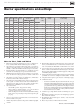
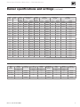
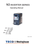
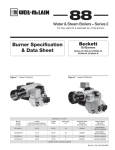
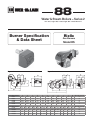
88
Water & Steam Boilers – Series 2
For Gas, Light Oil, & Gas/Light Oil – Fired Burners
Burner Specification
& Data Sheet
Figure 1
Gas Burners
Model RS
Figure 2
Model RS28 – 50 dimensions
Burner Model Number
Riello
Model RS70 – 190 dimensions
A
B
C
D
E
F
G
H
I
L
M
Approx. Wt. (pounds)
RS28/1
18.75
18.69
22.88
8.50
5.50
13.88
6.44
31.88
4.25
6.63
1.50
82
RS38/1
18.75
18.69
22.88
8.50
5.50
13.88
6.44
31.88
4.25
6.63
1.50
88
RS28/M
18.75
18.69
22.88
8.50
5.50
13.88
6.44
31.88
4.25
6.63
1.50
84
RS38/M
18.75
18.69
22.88
8.50
5.50
13.88
6.44
31.88
4.25
6.63
1.50
88
RS50/M
18.75
18.69
22.88
8.50
5.50
13.88
6.44
31.88
4.25
6.63
1.50
91
Burner Model Number
A
B
C
D
E
F
G
H
I
L
M
N
O
Approx. Wt. (pounds)
RS70/M
20.13
11.63
8.50
21.88
33.00
9.88 – 15.19
7.06
16.94
45.75 – 51.00
8.44
5.31
8.75
2.00
154
RS100/M
20.06
12.31
8.50
21.88
33.00
9.88 – 15.19
7.06
16.94
45.75 – 51.00
8.44
5.31
8.75
2.00
161
RS130/M
21.75
13.31
8.50
21.88
33.00
11.00 – 15.19
7.06
16.94
45.75 – 51.00
8.44
5.31
8.75
2.00
168
RS190/M
26.81
14.41
12.40
21.88
33.70
14.65 – 20.87
8.74
16.93
51.65
7.32
5.91
7.32
2.00
181
Part No. 550-142-025/0508
Weil-McLain 88 Water and Steam Boilers — Series 2 — For Gas, Light Oil, & Gas/Light Oil-Fired Burners
Burner specifications and settings
Table 1
Boiler
Model
Number
Burner data — Natural gas — Modulating
Burner
Model
Number
Pressure
Drop Thru
Gas Train .
Manifold
Pressure
Inches W.C. Inches W.C.
Gas Pressure Required at
Gas Control Inlet
Gas Pilot
Pressure
Min
Inches W.C
Max
Inches W.C
Inches W.C.
Combustion
Head
Setting
Combustion
Air Settings
Servo Motor Cam
Position Settings
488R
RS28/M
0.75
3.30
4.05
14
5.00
3
27
52
0
22
90
—
—
—
488
RS28/M
0.75
3.60
4.30
14
5.00
4
27
52
0
22
90
—
—
—
588
RS38/M
1.30
3.70
5.00
14
5.00
2
17
70
0
25
90
—
—
—
688
RS50/M
1.83
2.90
4.73
14
2.70
3
16
65
0
18
90
—
—
—
788
RS50/M
2.40
3.50
5.85
14
2.50
4
28
85
0
20
90
—
—
—
888
RS70/M
2.98
3.70
6.63
14
8.25
3
2.5
7.0
—
—
—
130
0
35
988R
RS70/M
3.16
3.87
7.03
14
8.25
4
2.5
7.5
—
—
—
130
0
35
988
RS70/M
3.16
4.10
7.28
14
8.25
5
2.5
7.5
—
—
—
130
0
35
1088R
RS70/M
3.00
4.65
7.65
14
6.50
8
3.0
8.5
—
—
—
130
0
40
1088
RS70/M
3.00
4.90
7.90
14
6.50
9
3.0
8.5
—
—
—
130
0
40
1188
RS100/M
3.80
3.10
6.90
14
6.50
4
2.5
6.0
—
—
—
130
0
35
1288
RS100/M
3.82
3.63
7.45
14
7.50
4
3.0
6.5
—
—
—
130
0
35
1388
RS100/M
2.41
4.50
6.91
14
7.60
3
2.5
9.0
—
—
—
130
0
30
1488
RS130/M
3.76
3.30
7.01
14
7.80
5
2.0
7.0
—
—
—
130
0
50
1588
RS130/M
4.09
3.50
7.59
14
7.20
7
2.5
7.0
—
—
—
130
0
50
1688R
RS130/M
3.19
3.45
6.64
14
7.20
8
2.5
8.5
—
—
—
130
0
30
1688
RS130/M
3.19
3.70
6.89
14
7.20
9
2.5
8.5
—
—
—
130
0
30
1788
RS130/M
3.70
4.80
8.50
14
7.20
9
2.5
9.0
—
—
—
130
0
55
1888
RS190/M
3.71
3.50
7.21
14
5.00
0
0.5
3.8
—
—
—
130
0
45
Notes for Table 1, Table 2 and Table 3
1. Burner capacities listed for elevations up to 2,000 feet. For higher elevations, consult local Weil-McLain distributor/agent or sales office.
2. Gas ratings based on natural gas with heating value of 1,000 Btu per
cubic foot and specific gravity of 0.60. Gas burners for other gases are
available. Consult local Weil-McLain distributor/agent or sales office.
10. Burners will be completely assembled and wired (except gas train) and
factory test-fired. Burners listed by Underwriters Laboratories, Inc.,
state of Connecticut, Fire Marshal state of Massachusetts, city of New
York MEA, and others.
3. Boiler-burner unit to be adjusted to achieve +0.10 inches W.C. pressure
at the flue collar, resulting in positive pressure in firebox as listed.
11. Special controls can be provided to meet other code requirements not
listed. Consult your local Weil-McLain distributor/agent or sales office.
Electric gas pilot will be furnished as standard equipment on all gas and
combination gas/light oil units.
4. Minimum gas pressures listed are subject to variations due to job conditions. Gas burners for other gas pressures are available. Consult local
Weil-McLain distributor/agent or sales office.
12. Direct spark ignition is standard for light oil units. Direct spark ignition
is available as an option for combination gas/light oil units. Consult
your local Weil-McLain distributor/agent or sales office.
5. All settings and pressures shown are for initial start-up. Final values
should be confirmed with combustion analysis.
13. All 3 phase models require a separate 120/60/1 control voltage supply.
6. Gas train sizes for models 488R to 1288 are based on a supply pressure
to the regulator of 7 inches W.C. Gas train sizes for models 1388 to
1888 are based on a supply pressure to the regulator of 12 inches W.C.
Optional trains are available for other pressures upon request.
7. Gas Control Systems:
14. Combustion Controls:
•
Siemens LFL 1.335 flame safeguard control monitors the oil or gas
burner flame with visual diagnostic window, provides pre-purge and
post purge, provides switching necessary to allow firing rate motor to
be driven to both low fire and high fire positions, prevent start up if
pre-ignition interlocks are open and has low fire start proven circuit.
In the event pre-ignition interlock circuit or running interlock circuit
does not “prove”, system will lock out on safety. Ultra violet sensitive
electronic flame detector is standard.
•
OO: On - Off operation. Single-position air damper
•
LHL: Low-high-low-off firing conditions – two-position air and fuel
controlled by separate motor, open damper pre-purge.
MOD: On - Off operation with proven low fire start and full modulating
firing conditions. Proportional motor drives fuel metering valve and
combustion air damper according to firing conditions; open damper
pre-purge.
15. All units require a single SPDT controller for LHL firing rate operation.
8. 120/60/1 control circuit is used for all burners. Control circuit transformer is available as an option.
17. Modulating units 888 to 1888 require a 4 – 20mA, 0 – 10vdc or 135 ohm
signal for modulation.
9. Airflow safety switch is standard for all gas and combination gas/light
oil units.
18. Motor relay or contractor will be furnished on all units.
•
2
16. Modulating units 488R to 788 require a 120v bumping type signal or
PID control for modulation.
Part No. 550-142-025/0508
Burner Specification & Data sheet — Riello Gas Burners
Burner specifications and settings
Table 2
(continued)
Burner data — Natural gas — General
Boiler
Model
Number
Burner
Input
488R
996
Positive
Pressure In
Firebox
Standard Burner Model
Designation
Standard
Combustion
Control
Standard
Control System
Burner Motor H.P.
3400 RPM
Standard
Motor Voltage
Inches W.C.
On - Off
LHL/MOD
Note 14
On - Off
LHL/MOD
On - Off
LHL/MOD
On - Off
LHL/MOD
.89
RS28/1
RS28/M
LFL 1.335**
00
LHL/MOD
1/2
1/2
120/60/1
120/60/1
488
1010
1.00
RS28/1
RS28/M
LFL 1.335**
00
LHL/MOD
1/2
1/2
120/60/1
120/60/1
588
1357
.89
RS38/1
RS38/M
LFL 1.335**
00
LHL/MOD
1/2
1/2 OR 3/4
120/60/1
120/60/1
688
1703
.72
—
RS50/M
LFL 1.335**
—
LHL/MOD
—
3/4
—
120/60/1 or 3 phase*
788
2049
.65
—
RS50/M
LFL 1.335**
—
LHL/MOD
—
3/4
—
3 phase*
888
2396
.85
—
RS70/M
LFL 1.335**
—
LHL/MOD
—
1 1/2
—
3 phase*
988R
2482
.80
—
RS70/M
LFL 1.335**
—
LHL/MOD
—
1 1/2
—
3 phase*
988
2713
.80
—
RS70/M
LFL 1.335**
—
LHL/MOD
—
1 1/2
—
3 phase*
1088R
2887
.82
—
RS70/M
LFL 1.335**
—
LHL/MOD
—
1 1/2
—
3 phase*
1088
3103
.82
—
RS100/M
LFL 1.335**
—
LHL/MOD
—
2 1/2
—
3 phase*
1188
3392
.82
—
RS100/M
LFL 1.335**
—
LHL/MOD
—
2 1/2
—
3 phase*
1288
3753
.81
—
RS100/M
LFL 1.335**
—
LHL/MOD
—
2 1/2
—
3 phase*
1388
4113
.89
—
RS100/M
LFL 1.335**
—
LHL/MOD
—
2 1/2
—
3 phase*
1488
4474
.86
—
RS130/M
LFL 1.335**
—
LHL/MOD
—
3
—
3 phase*
1588
4763
.86
—
RS130/M
LFL 1.335**
—
LHL/MOD
—
3
—
3 phase*
1688R
4979
.863
—
RS130/M
LFL 1.335**
—
LHL/MOD
—
3
—
3 phase*
1688
5124
.83
—
RS130/M
LFL 1.335**
—
LHL/MOD
—
3
—
3 phase*
1788
5485
.82
—
RS130/M
LFL 1.335**
—
LHL/MOD
—
3
—
3 phase*
1888
5845
.85
—
RS190/M
LFL 1.335**
—
LHL/MOD
—
3
—
3 phase*
*208/60/3, 240/60/3, 480/60/3, 575/60/3, burner motor voltage must be specified
Table 3
Boiler
Model
Number
Gas control components and sizes
Manual
Hand Valve
Low Gas
Pressure Switch
Inches
Gas
Pressure Regulator
Operating
Gas Valve
Operating Gas
Valve (with Proof Of
Closure)
Safety
Gas Valve
Manual
Checking Gas Valve
High Gas
Pressure Switch
Inches
Inches
Inches
Inches
488R – 688
1 1/2
Standard
1 1/2
1 1/2
Optional
1 1/2
1 1/2
Standard
788 – 1188
2
Standard
2
2
Optional
2
2
Standard
1288 – 1688R
2 1/2
Standard
2 1/2
2 1/2
Optional
2 1/2
2 1/2
Standard
1688 – 1888
3
Standard
3
3
Optional
3
3
Standard
Part No. 550-142-025/0508
3
Weil-McLain 88 Water and Steam Boilers — Series 2 — For Gas, Light Oil, & Gas/Light Oil-Fired Burners
4
Part No. 550-142-025/0508