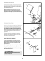
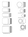
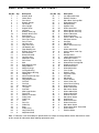
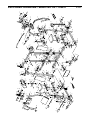
1
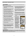
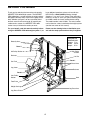
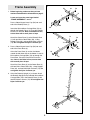
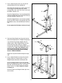
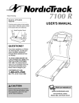
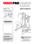
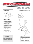
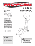
Model No. 831.159531
Serial No.
The serial number is found in the
location shown below. Write the
serial number in the space above.
USER’S MANUAL
Serial Number Decal
SEARS, ROEBUCK AND CO.
HOFFMAN ESTATES, IL 60179
CAUTION
Read all precautions and instructions in this manual before using
this equipment. Save this manual for future reference.
Patent Pending
Visit our website at
www.weiderfitness.com
new products, prizes,
fitness tips, and much more!
TABLE OF CONTENTS
IMPORTANT PRECAUTIONS . . . . . . . . . . . . . . . . . . . . . . . . . . . . . . . . . . . . . . . . . . . . . . . . . . . . . . . . . . . . . 3
BEFORE YOU BEGIN . . . . . . . . . . . . . . . . . . . . . . . . . . . . . . . . . . . . . . . . . . . . . . . . . . . . . . . . . . . . . . . . . . . 4
ASSEMBLY . . . . . . . . . . . . . . . . . . . . . . . . . . . . . . . . . . . . . . . . . . . . . . . . . . . . . . . . . . . . . . . . . . . . . . . . . . .5
ADJUSTMENT . . . . . . . . . . . . . . . . . . . . . . . . . . . . . . . . . . . . . . . . . . . . . . . . . . . . . . . . . . . . . . . . . . . . . . . 23
WEIGHT RESISTANCE CHART . . . . . . . . . . . . . . . . . . . . . . . . . . . . . . . . . . . . . . . . . . . . . . . . . . . . . . . . . . .25
CABLE DIAGRAMS . . . . . . . . . . . . . . . . . . . . . . . . . . . . . . . . . . . . . . . . . . . . . . . . . . . . . . . . . . . . . . . . . . . .26
TROUBLE-SHOOTING AND MAINTENANCE . . . . . . . . . . . . . . . . . . . . . . . . . . . . . . . . . . . . . . . . . . . . . . . . 27
ORDERING REPLACEMENT PARTS . . . . . . . . . . . . . . . . . . . . . . . . . . . . . . . . . . . . . . . . . . . . . . . Back Cover
FULL 90-DAY WARRANTY . . . . . . . . . . . . . . . . . . . . . . . . . . . . . . . . . . . . . . . . . . . . . . . . . . . . . . . Back Cover
Note: A PART LIST/EXPLODED DRAWING and a PART IDENTIFICATION CHART are attached in the center of
this manual. Remove the PART LIST/EXPLODED DRAWING and the PART IDENTIFICATION CHART before
beginning assembly.
2
IMPORTANT PRECAUTIONS
WARNING:
To reduce the risk of serious injury, read the following important precautions before using the weight system.
1. Read all instructions in this manual and in
the accompanying literature before using the
weight system.
12. Do not place more than 200 pounds on either
weight carriage. Always place the same
amount of weight (not included) on both
sides of each weight carriage.
2. It is the responsibility of the owner to ensure
that all users of the weight system are adequately informed of all precautions.
13. Never release the press arms, butterfly arms,
leg lever, lat bar, or ab strap while weights
are raised. The weights will fall with great
force.
3. The weight system is intended for home use
only. Do not use the weight system in a commercial, rental, or institutional setting.
14. Always disconnect the lat bar or ab strap
from the weight system when performing an
exercise that does not use the attachments.
4. Use the weight system only on a level surface. Cover the floor or carpet beneath the
weight system to protect the floor or carpet.
15. If you feel pain or dizziness at any time while
exercising, stop immediately and begin cooling down.
5. Make sure all parts are properly tightened
each time you use the weight system.
Replace any worn parts immediately.
16. The warning decals
shown here have
been placed on the
weight system in the
locations shown on
page 4. Note that
decal 1 has been
placed in two locations. If a decal is
missing or illegible,
please call our tollfree HELPLINE at
1-800-736-6879,
Monday through
Saturday, 7 a.m. until
7 p.m. Central Time,
to order a free
replacement decal.
Place the decal on
the weight system in
the location shown.
6. Keep children under the age of 12 and pets
away from the weight system at all times.
7. The weight system is designed to be used by
one or two people, and to support a maximum
weight of 250 pounds per person.
8. Always wear athletic shoes for foot protection when exercising.
9. Keep hands and feet away from moving parts.
10. Make sure the cables remain on the pulleys
at all times. If the cables bind while you are
exercising, stop immediately and make sure
the cables are on all of the pulleys.
11. Always stand on the foot plate when performing an exercise that could cause the weight
system to tip.
Decal 1
Keep hands and
fingers clear of
this area.
Decal 2
WARNING:
Before beginning this or any exercise program, consult your physician. This
is especially important for persons over the age of 35 or persons with pre-existing health problems.
Read all instructions before using. SEARS assumes no responsibility for personal injury or property
damage sustained by or through the use of this product.
3
BEFORE YOU BEGIN
Thank you for selecting the innovative and versatile
WEIDER® PRO 9950 weight system. The WEIDER®
PRO 9950 offers a unique selection of weight stations
designed to develop every major muscle group of the
body. Whether your goal is to tone your body, build
dramatic muscle size and strength or improve your
cardiovascular system, the WEIDER® PRO 9950
makes it easy to achieve the results you want.
have additional questions, please call our toll-free
HELPLINE at 1-800-736-6879, Monday through
Saturday, 7 a.m. until 7 p.m. Central Time (excluding
holidays). To help us assist you, please note the product model number and serial number before calling.
The model number is 831.159531. The serial number
can be found on a decal attached to the weight system
(see the front cover of this manual).
For your benefit, read this manual carefully before
using the WEIDER® PRO 9950 weight system. If you
Please use the drawing below to familiarize yourself with the major parts and how they fit together.
ASSEMBLED
DIMENSIONS:
Height: 77 in.
Width: 103 in.
Depth: 57 in.
Butterfly Arms
Decal 1
Ab Pulley Station
High Pulley
Station
Backrest
Lat Bar
Decal 1
Curl Pad
Press Arms
Leg Lever
Backrest
Decal 2
Low Pulley
Station
Seat
Foot Plate
Weight Carriage
Leg Press Arm
Leg Press Plate
4
ASSEMBLY
Make sure you have the following tools:
Make Assembly Easier for Yourself
• Two adjustable wrenches
Everything in this manual is designed to
ensure that the weight system can be assembled successfully by anyone. Before beginning assembly, make sure to read the
information on this page. This brief introduction will save you much more time than
it takes to read it.
• One standard screwdriver
• One phillips screwdriver
• One rubber mallet
• You will also need grease or petroleum jelly, a
small amount of soapy water, and clear tape or
masking tape.
Assembly Requires Two Persons
For your convenience and safety, assemble the
weight system with the help of another person.
Note: Assembly will be more convenient if you have
a socket set, a set of open-end or closed-end
wrenches, or a set of ratchet wrenches.
Set Aside Enough Time
How to Identify Parts
Due to the many features of the weight system, the
assembly process will take time. By setting aside
plenty of time and by deciding to make the task
enjoyable, assembly will go smoothly. You may want
to assemble the weight system over a couple of
evenings.
To help you identify the small parts used in assembly,
we have included a PART IDENTIFICATION CHART
in the center of this manual. Place the chart on the
floor and use it to easily identify parts during each
assembly step. Note: Some small parts may have
been pre-attached. If a part is not in the parts
bag, check to see if it has been pre-attached.
Select a Location for the Weight System
How to Orient Parts
Because of its weight and size, the weight system
should be assembled in the location where it will be
used. Make sure that there is enough room to walk
around the weight system as you assemble it.
As you assemble the weight system, make sure that
all parts are oriented exactly as shown in the drawings.
How to Unpack the Box
Tightening Parts
To make assembly as easy as possible, we have
divided the assembly process into four stages. The
parts needed for each stage are found in individual
bags. Important: Wait until you begin each stage
to open the parts bag for that stage. Place all
parts of the weight system in a cleared area and
remove the packing materials. Do not dispose of
the packing materials until assembly is completed.
Tighten all parts as you assemble them, unless
instructed to do otherwise.
Questions?
If you have questions after reading the assembly
instructions, please call our HELPLINE at
1-800-736-6879.
The Four Stages of the Assembly Process
Frame Assembly—You will begin by assembling
the base and the uprights that form the skeleton of
the weight system.
Cable Assembly—During this stage you will
attach the cables and pulleys that connect the
arms to the weights.
Arm Assembly—During this stage you will
assemble the arms and the leg lever.
Seat Assembly—During the final stage you will
assemble the seats and the backrests.
5
Frame Assembly
1
58
59
34
1. Before beginning, make sure that you have
read and understood the information on page 5.
74
1
Locate and open the parts bags labeled
“FRAME ASSEMBLY 1 and 2.”
74
76
Press a 50mm Square Inner Cap (59) into each
end of the Butterfly Base (1).
2
76
59
Insert four M10 x 65mm Carriage Bolts (76) up
through the Butterfly Base (1). Place the Butterfly
Base flat on the floor. Note: If the Bolts fall out,
secure them with a small piece of tape.
2
74
Attach the Center Base (2) to the Butterfly Base
(1) with two M10 x 70mm Bolts (58), a Long
Support Plate (34), and two M10 Nylon Locknuts
(74). Do not tighten the Nylon Locknuts yet.
59
2
74
2. Press a 50mm Square Inner Cap (59) into each
end of the Press Base (3).
34
3
76
59
Orient the Press Base (3) so that the indents
around the bolt holes are on the bottom. Insert six
M10 x 65mm Carriage Bolts (76) up through the
Press Base. Place the Press Base flat on the
floor. Note: If the Bolts fall out, secure them
with a small piece of tape.
76
76
3
Attach the Press Base (3) to the Center Base (2)
with two M10 x 70mm Bolts (58), a Long Support
Plate (34), and two M10 Nylon Locknuts (74). Do
not tighten the Nylon Locknuts yet.
3. Orient the Butterfly Upright (4) as shown. Attach
the Butterfly Upright to the indicated M10 x 65mm
Carriage Bolts (76) in the Butterfly Base (1) with
two M10 Nylon Locknuts (74). Do not tighten the
Nylon Locknuts yet.
4
74
74
76
1
6
58
4. Press a 38mm Square Inner Cap (75) into the
indicated tube on the Press Upright (6).
4
Orient the Press Upright (6) as shown. Attach the
Press Upright to the indicated M10 x 65mm
Carriage Bolts (76) in the Press Base (3) with two
M10 Nylon Locknuts (74).
75
Attach the Support Brace (7) to the indicated M10
x 65mm Carriage Bolts (76) in the Press Base (3)
with two M10 Nylon Locknuts (74).
74
95
Attach the Support Brace (7) to the Press Upright
(6) with two M10 x 70mm Carriage Bolts (58), two
M10 Washers (95), and two M10 Nylon Locknuts
(74).
7
74
58
6
74
74
Do not tighten the M10 Nylon Locknuts (74) yet.
74
76
76
3
5. Press two 25mm Round Inner Caps (32) into the
ends of the weight tube on a Weight Carriage (28).
5
27
32
If you will be using Olympic weights with the
weight system, slide a Weight Sleeve (27) onto
each end of the weight tube on the Weight
Carriage (28). Secure each Weight Sleeve with a
Locking Pin (31). Note: The drawings in this
manual show the Weight Sleeves attached.
The Locking Pins will be found in the bag
labeled “CABLE ASSEMBLY.”
28
31
27
31
Weight
Tube
Repeat this step with the other Weight Carriage
(28).
6
6. Press a 38mm Round Inner Cap (67) into each
bumper tube on the Center Base (2). Press a
Weight Bumper (56) onto each bumper tube.
33
33
Attach two Weight Guides (33) to the indicated
tube in the Center Base (2) with an M10 x 155mm
Bolt (89), two M10 Washers (95), and an M10
Nylon Locknut (74). Do not tighten the Nylon
Locknuts yet.
67
56
74
95
95
Attach the other set of Weight Guides (33) in the
same manner.
67
56
Tube
89
Bumper
Tube
2
7
7. Slide a Weight Carriage (28) onto each set of
Weight Guides (33). Be sure the weight tubes
are near the top of the Weight Carriages.
7
Weight
Tube
33
28
33
28
8. Attach the Top Frame (5) to the Butterfly Upright
(4) with two M10 x 70mm Bolts (58), a Short
Support Plate (26), and two M10 Nylon Locknuts
(74). Do not tighten the Nylon Locknuts yet.
8
58
26
5
Note: Be sure that the Top Frame (5) is oriented so that the pulley brackets are closer to
the back of it, and that it rests between the
Weight Guides (33) as shown in step 9.
Pulley Bracket
58
26
74
Attach the Top Frame (5) to the Press Upright (6)
in the same manner.
33
4
33
6
9. Attach each set of Weight Guides (33) to the Top
Frame (5) with an M10 x 155mm Bolt (89), two
M10 Washers (95), and an M10 Nylon Locknut
(74). Do not tighten the Nylon Locknuts yet.
74
9
74
95
95
89
33
5
33
10. Press three 50mm Square Inner Caps (59) into
the Butterfly Top Frame (19).
10
34
58
Attach the Butterfly Top Frame (19) to the
Butterfly Upright (4) with two M10 x 70mm Bolts
(58), a Long Support Plate (34), and two M10
Nylon Locknuts (74).
58
59
59
Attach the Butterfly Top Frame (19) to the Top
Frame (5) with two M10 x 70mm Bolts (58), a
Long Support Plate (34), and two M10 Nylon
Locknuts (74).
19
59
74
5
74
Do not tighten the M10 Nylon Locknuts (74)
yet.
4
8
74
11. Press a 50mm Square Inner Cap (59) into the
Press Top Frame (13).
11
58
59
Attach the Press Top Frame (13) to the Press
Upright (6) with two M10 x 70mm Bolts (58), a
Long Support Plate (34), and two M10 Nylon
Locknuts (74).
5
34
34
74
58
Attach the back hole on the side of the Press Top
Frame (13) to the Top Frame (5) with an M10 x
70mm Bolt (58), the Long Support Plate (34), and
an M10 Nylon Locknut (74).
62
44
13
37
6
Attach the next hole on the side of the Press Top
Frame (13), a 90mm Pulley (37) and a Cable Trap
(44) to the Top Frame (5) with an M10 x 95mm Bolt
(62), the Long Support Plate (34), and an M10
Nylon Locknut (74). Do not overtighten the Nylon
Locknut; the Pulley must be able to turn easily.
74
12
58
59
Do not tighten the M10 Nylon Locknuts (74) yet.
74
95
12
12. Attach a Bumper (71) and an M6 Washer (84) to
the Press Seat Frame (12) with a Bumper Screw
(72).
84 71
74
72
Attach the Press Seat Frame (12) to the M10 x
65mm Carriage Bolts (76) in the Press Base (3)
with two M10 Nylon Locknuts (74).
6
3
74
76
Attach the Press Seat Frame (12) to the Press
Upright (6) with two M10 x 70mm Bolts (58), two
M10 Washers (95), and two M10 Nylon Locknuts
(74).
13
Adjustment knob
must be on this side
95
Do not tighten the M10 Nylon Locknuts (74) yet.
13. Attach the Butterfly Seat Frame (10) to the
Butterfly Front Leg (9) with two M10 x 70mm
Bolts (58), two M10 Washers (95), and two M10
Nylon Locknuts (74). Do not tighten the Nylon
Locknuts yet. Be sure the Adjustment Knob
(not shown) is on the indicated side.
10
74
58
95
9
14
14. Attach a Bumper (71) and an M6 Washer (84) to
the Butterfly Front Leg (9) with a Bumper Screw
(72).
10
95
58
74
Attach the Butterfly Front Leg (9) to the M10 x
65mm Carriage Bolts (76) in the Butterfly Base
(1) with two M10 Nylon Locknuts (74).
84 71
72
Attach the Butterfly Seat Frame (10) to the
Butterfly Upright (4) with two M10 x 70mm Bolts
(58), two M10 Washers (95), and two M10 Nylon
Locknuts (74).
95
9
4
74
74
1
76
Properly tighten the M10 Nylon Locknuts (74)
used in steps 1–14.
9
Arm Assembly
15
74
59
9
15. Locate and open the parts bag labeled “ARM
ASSEMBLY.”
93
8
Press a 50mm Square Inner Cap (59) into each
end of the Leg Lever (8).
Lubricate the M10 x 81mm Bolt (93). Attach the
Leg Lever (8) to the Butterfly Front Leg (9) with
the Bolt and an M10 Nylon Locknut (74). Do not
overtighten the Nylon Locknut; the Leg Lever
must be able to pivot easily.
Lubricate
59
16. Press two 45mm Square Inner Caps (60) into the
ends of the the Right Butterfly Arm (18). Press
two Handgrips (65) onto the handle on the Right
Butterfly Arm.
16
60
65
Assemble the Left Butterfly Arm (17) in the same
manner.
18
Handle
17
60
65
17. Lubricate both axles on the Butterfly Top Frame
(19). Slide the Right Butterfly Arm (18) onto the
indicated axle. Be sure the upper end of the
Butterfly Arm is behind the bracket on the
Butterfly Top Frame.
17
19
Bracket
Axle
Tap two 25mm Retainers (85) and a 25mm
Round Cover Cap (86) onto the axle. Be sure
that the teeth on the Retainers bend toward
the Round Cover Cap, as shown in the inset
drawing.
18
85
17
86
Attach the Left Butterfly Arm (17) in the same
manner.
Axle
85
86
10
18. Press two 45mm Square Inner Caps (60) into the
top of the Press Frame (14). Press six M10 Brass
Bushings (77) into the Press Frame and the
Press Top Frame (13).
18
13
77
Lubricate the M10 x 228mm Bolt (92). Attach the
Press Frame (14) to the Press Top Frame (13)
with the Bolt and an M10 Nylon Locknut (74). Do
not overtighten the Nylon Locknut; the Press
Frame must be able to pivot easily.
77
74
60
60
77
77
14
92
19. Press a 45mm Square Inner Cap (60) into the
bottom of the Right Press Arm (16). Press two
Handgrips (65) onto the handle.
19
16
Assemble the Left Press Arm (15) in the same
manner.
65
15
Handle
60
65
20. Attach the Right Press Arm (16) to the Press
Frame (14) with two M10 x 65mm Bolts (78) and
two M10 Nylon Locknuts (74).
20
16
Attach the Left Press Arm (15) in the same manner.
74
78
11
14
15
21. Press four M10 Brass Bushings (77) into the Leg
Press Arm (22) and the Press Base (3).
21
Lubricate an M10 x 85mm Bolt (88). Orient the
Leg Press Arm (22) as shown. Attach the Leg
Press Arm to the Press Base (3) with the Bolt and
an M10 Nylon Locknut (74). Do not overtighten
the Nylon Locknut; the Leg Press Arm must
be able to pivot easily.
22
3
74
Lubricate
77
Cable Assembly
88
22
22. Locate and open the parts bag labeled
“CABLE ASSEMBLY.” For cable identification
and routing during steps 22 to 52, refer to the
CABLE DIAGRAMS and CABLE ID CHART on
page 26.
95
13
74
80
Rod
37
Do not overtighten the nylon locknuts attaching the pulleys to the weight system; the pulleys must be able to turn freely.
55
Ball
Identify the Press Cable (80). It is approximately
393.41” long and it has a ball on one end and a
loop on the other. Wrap the Press Cable around a
90mm Pulley (37). Attach the Pulley to the Press
Top Frame (13) with an M10 x 90mm Bolt (55),
an M10 Washer (95), and an M10 Nylon Locknut
(74). Be sure that the Cable is between the
Pulley and the rod on the Press Top Frame,
and that the ball is on the side shown.
23
44
62
37
80
23. Loosen the M10 Nylon Locknut (not shown) on
the indicated M10 x 95mm Bolt (62). Wrap the
Press Cable (80) around the 90mm Pulley (37),
making sure the Cable is between the Pulley and
the Cable Trap (44). Re-tighten the Nylon Locknut.
24. Wrap the Press Cable (80) around a 90mm
Pulley (37). Attach the Pulley to the indicated side
of the Press Frame (14) with an M10 x 85mm
Bolt (88), an M10 Washer (95), and an M10
Nylon Locknut (74).
24
74
14
37
80
12
95
88
25. Wrap the Press Cable (80) around a “V”-Pulley
(38). Attach the Pulley and a Long Cable Trap
(50) to the Press Upright (6) with an M10 x 95mm
Bolt (62), an M10 Washer (95), and an M10
Nylon Locknut (74). Be sure the Cable Trap is
turned to hold the Cable in the groove of the
Pulley.
25
62
38
80
50
6
95
74
26. Wrap the Press Cable (80) around a 90mm
Pulley (37). Attach the Pulley to the other side of
the Press Frame (14) with an M10 x 85mm Bolt
(88), an M10 Washer (95), and an M10 Nylon
Locknut (74).
26
88
14
95
80
37
27. Wrap the Press Cable (80) around a 90mm
Pulley (37). Attach the Pulley and a Cable Trap
(44) to the Press Upright (6) with an M10 x 95mm
Bolt (62), an M10 Washer (95), and an M10
Nylon Locknut (74). Make sure the Cable Trap
is turned to hold the Cable in the groove of
the Pulley.
74
27
74
37
44
80
95
6
28. Wrap the Press Cable (80) around a 90mm
Pulley (37). Attach the Pulley and a Cable Trap
(44) to the bottom of the Press Upright (6) with an
M10 x 95mm Bolt (62), an M10 Washer (95), and
an M10 Nylon Locknut (74). Make sure the
Cable Trap is turned to hold the Cable in the
groove of the Pulley.
62
28
6
74
37
80
44
62
95
13
29. Insert an M10 x 120mm Bolt (61) through a
90mm Pulley (37), a Cable Trap (44), and the Leg
Press Arm (22) from the indicated side. Be sure
the Cable Trap is oriented as shown.
29
80
74
Wrap the Press Cable (80) around another 90mm
Pulley (37). Attach the Pulley and a Cable Trap
(44) to the M10 x 120mm Bolt (61) with an M10
Nylon Locknut (74). Be sure the Cable Trap is
turned to hold the Cable in the groove of the
Pulley. Do not tighten the Nylon Locknut yet.
37
44
44
37
22
61
30. Wrap the Press Cable (80) around a “V”-Pulley
(38). Attach the Pulley and a Long Cable Trap
(50) to the indicated hole in the Press Seat
Frame (12), using an M10 x 105mm Bolt (69), an
M10 Large Washer (40) and an M10 Nylon
Locknut (74). Be sure the Cable Trap is turned
to hold the Cable in the groove of the Pulley.
30
69
40
12
50
38
74
80
31. Wrap the Press Cable (80) around the indicated
90mm Pulley (37) on the Leg Press Arm (22).
Make sure the Cable Trap is turned to hold the
Cable in the groove of the Pulley. Tighten the
M10 Nylon Locknut (not shown) used in step 29.
31
80
44
22
32. Wrap the Press Cable (80) around a 90mm
Pulley (37). Attach the Pulley and a Cable Trap
(44) to the Support Brace (7) with an M10 x
95mm Bolt (62), an M10 Washer (95), and an
M10 Nylon Locknut (74). Make sure the Cable
Trap is turned to hold the Cable in the groove
of the Pulley.
37
32
7
44
80
74
95
37 62
14
33. Wrap the Press Cable (80) around a 90mm
Pulley (37). Attach the Pulley to the bracket on
the Press Top Frame (13) with an M10 x 45mm
Bolt (96) and an M10 Nylon Locknut (74).
33
13
74
37
Bracket
96
34. Wrap the Press Cable (80) around a 90mm
Pulley (37). Attach the Pulley to the bracket on
the Top Frame (5) with an M10 x 45mm Bolt (96)
and an M10 Nylon Locknut (74).
34
80
74
5
Bracket
96
37
80
35. Remove the M10 x 65mm Bolt (78) from the top
of the indicated Weight Carriage (28). Attach the
end of the Press Cable (80) to the Weight
Carriage with the Bolt and M10 Nylon Locknut
(74).
35
80
78
74
28
36. Identify the Butterfly Cable (81); it is approximately 51.75” long and it has a loop on each end.
36
Attach one end of the Butterfly Cable (81) to the
bracket on the Left Butterfly Arm (17) with an M10
x 25mm Bolt (97) and an M10 Nylon Locknut
(74).
74
Bracket
81
97
17
15
37. Wrap the Butterfly Cable (81) around a “V”-Pulley
(38). Attach the Pulley and a Long Cable Trap
(50) to the indicated side of the bracket on the
Butterfly Upright (4) with a M10 x 60mm Bolt (79)
and an M10 Nylon Locknut (74). Be sure the
Long Cable Trap is turned to hold the Cable in
the groove of the Pulley.
37
50
38
79
81
Bracket
74
4
38. Remove the two 90mm Pulleys (37) and two
Cable Traps (44) from the set of Pulley Plates
(43). Wrap the Butterfly Cable (81) around a
Pulley. Reattach the Pulley and a Cable Trap to
the top set of holes in the Pulley Plates with an
M10 x 45mm Bolt (96) and an M10 Nylon Locknut
(74). Be sure the Cable Trap is turned to hold
the Cable in the groove of the Pulley.
38
81
37
74
44
96
43
39. Wrap the Butterfly Cable (81) around a “V”-Pulley
(38). Attach the Pulley and a Long Cable Trap
(50) to the other side of the bracket on the
Butterfly Upright (4) with an M10 x 60mm Bolt
(79) and an M10 Nylon Locknut (74). Be sure the
Long Cable Trap is turned to hold the Cable in
the groove of the Pulley.
39
79
38
81
50
74
4
40. Attach the end of the Butterfly Cable (81) to the
bracket on the Right Butterfly Arm (18) with an
M10 x 25mm Bolt (97) and an M10 Nylon Locknut
(74).
40
81
Bracket 74
97
18
16
41. Identify the Ab Cable (83); it is approximately
220.40” long and it has a ball on one end and a
loop on the other.
41
Large tabs
must be on
this side
91 95
Wrap the Ab Cable (83) around a 90mm Pulley
(37). Place two Pulley Covers (49) over the
Pulley; make sure that the large tabs are in the
position shown. Attach the Pulley and Pulley
Covers to the Butterfly Upright (4) with an M10 x
100mm Bolt (91), two M10 Washers (95), and an
M10 Nylon Locknut (74). Be sure that the Cable
is between the Pulley and the rod on the
Upright, and that the ball is on the side
shown.
49
37
Rod
Ball
4
42. Remove the two 90mm Pulleys (37) from the
Double “U”-Bracket (42). Wrap the Ab Cable (83)
around a Pulley. Reattach the Pulley to the
Double “U”-Bracket with an M10 x 45mm Bolt
(96) and an M10 Nylon Locknut (74).
83
95
49
42
83
37
74
96
42
43. Wrap the Ab Cable (83) around the other 90mm
Pulley (37) removed in step 38. Reattach the
Pulley and Cable Trap (44) to the bottom set of
holes in the Pulley Plates (43) with an M10 x
45mm Bolt (96) and an M10 Nylon Locknut (74).
Be sure the Cable Trap is turned to hold the
Cable in the groove of the Pulley.
43
43
74
96
44
83
44. Wrap the Ab Cable (83) around a 90mm Pulley
(37). Attach the Pulley and a Cable Trap (44) to
the bracket on the Butterfly Base (1) with an M10
x 45mm Bolt (96) and an M10 Nylon Locknut (74).
Make sure the Cable Trap is oriented as
shown.
37
44
83
96
1
44
37
74
Bracket
17
74
45. Wrap the Ab Cable (83) around a 90mm Pulley
(37). Attach the Pulley to the bracket on the
Butterfly Top Frame (19) with an M10 x 45mm
Bolt (96) and an M10 Nylon Locknut (74).
45
19
Bracket
96
74
37
83
46. Wrap the Ab Cable (83) around a 90mm Pulley
(37). Attach the Pulley to the bracket on the Top
Frame (5) with an M10 x 45mm Bolt (96) and an
M10 Nylon Locknut (74).
46
5
74
83
96
37
47. Remove the M10 x 65mm Bolt (78) from the top
of the indicated Weight Carriage (28). Attach the
end of the Ab Cable (83) to the Weight Carriage
with the Bolt and M10 Nylon Locknut (74).
Bracket
47
83
78
28
74
48. Identify the Leg Lever Cable (82). It is approximately 140.62” long and it has a ball on one end
and a loop on the other.
48
Route the loop end of the Leg Lever Cable (82)
through the cage on the Butterfly Base (1) and
under a 90mm Pulley (37). Attach the Pulley and
a Cable Trap (44) to the bracket on the Butterfly
Base with an M10 x 45mm Bolt (96) and an M10
Nylon Locknut (74). Make sure the Cable Trap
is oriented to hold the Cable in the groove of
the Pulley.
96
37
Bracket
44
1
Cage
82
18
74
49. Wrap the Leg Lever Cable (82) around a 90mm
Pulley (37). Attach the Pulley and a Cable Trap
(44) to the Butterfly Upright (4) with an M10 x
120mm Bolt (61) and an M10 Nylon Locknut (74).
Do not tighten the Nylon Locknut yet. Be sure
that the Cable Trap is turned to hold the Cable
in the groove of the Pulley.
49
61
82
37
44
4
50. Wrap the Leg Lever Cable (82) around the 90mm
Pulley (37) removed in step 42. Attach the Pulley
to the bottom of the Double “U”-Bracket (42) with
an M10 x 45mm Bolt (96) and an M10 Nylon
Locknut (74).
74
50
74
96
42
37
82
51. Remove the M10 Nylon Locknut (74) used in step
49.
51
4
Wrap the Leg Lever Cable (82) around a 90mm
Pulley (37). Attach the Pulley and a Cable Trap
(44) to the M10 x 120mm Bolt (61) in the Butterfly
Upright (4) with an M10 Nylon Locknut (74). Be
sure that the Cable Trap is turned to hold the
Cable in the groove of the Pulley.
82
61
44
52. Attach the end of the Leg Lever Cable (82) to the
Leg Lever (8) with an M10 x 70mm Short Thread
Bolt (99), three M10 Washers (95), and an M10
Nylon Locknut (74). Do not overtighten the
Nylon Locknut; the Cable must be able to
pivot freely.
52
8
74
95
95
82
99
19
37
74
Seat Assembly
53
25
53. Locate and open the parts bag labeled “SEAT
ASSEMBLY.”
70
Press a 25mm x 40mm Inner Cap (63) into the
bottom of a Seat Bracket (11). Press two 25mm x
50mm Inner Caps (70) into the ends of the Seat
Bracket.
11
70
Oreint the Seat (25) as shown. Attach the Seat to
the bracket on a Seat Bracket (11) with two M6 x
16mm Screws (90). Attach the other end of the
Seat to the Seat Bracket with an M6 x 45mm
Screw (98) and an M6 Washer (84).
90
63
84
98
10
Loosen the Adjustment Knob (not shown) by turning it counterclockwise, and pull it out as far as
possible. Insert the Seat Bracket (11) into the
Butterfly Seat Frame (10) and align an adjustment
hole with the Adjustment Knob. Snap the Knob into
the adjustment hole and turn it clockwise until it is
tight.
54
94
54. Attach the Butterfly Backrest (53) to the Butterfly
Upright (4) with two M6 x 65mm Screws (94) and
two M6 Washers (84).
84
4
53
84
94
55. Press a 25mm x 40mm Inner Cap (63) into the
bottom of the other Seat Bracket (11). Press two
25mm x 50mm Inner Caps (70) into the ends of
the Seat Bracket.
55
25
Orient the other Seat (25) as shown. Attach the
Seat to the bracket on the other Seat Bracket (11)
with two M6 x 16mm Screws (90). Attach the
other end of the Seat to the Seat Bracket with an
M6 x 45mm Screw (98) and an M6 Washer (84).
70
11
Loosen the Adjustment Knob (51) by turning it
counterclockwise, and pull it out as far as possible. Insert the Seat Bracket (11) into the Press
Seat Frame (12) and align an adjustment hole
with the Adjustment Knob. Snap the Knob into the
adjustment hole and turn it clockwise until it is
tight.
84
70
98
90
63
12
51
20
56. Press a 25mm x 40mm Inner Cap (63) into the
back of the Backrest Bracket (21). Press two
25mm x 50mm Inner Caps (70) into the top and
bottom of the Backrest Bracket.
56
98
70
84
Insert an M8 x 40mm Carriage Bolt (54) into the
center hole of the Support Plate (57). Attach the
Support Plate to Press Backrest (20) with two M6
x 16mm Screws (90). Attach the Backrest to the
Backrest Bracket (21) with the Carriage Bolt, an
M8 Washer (66), and an M8 Nylon Locknut (64).
Attach the top of the Backrest to the Backrest
Bracket with an M6 x 45mm Screw (98) and an
M6 Washer (84).
21
63
90
64
57
20
51
66
6
90
54
70
Loosen the Adjustment Knob (51) by turning it
counterclockwise, and pull it out as far as possible. Insert the Backrest Bracket (21) into the
Press Upright (6) and align an adjustment hole
with the the Adjustment Knob. Snap the Knob into
the adjustment hole and turn it clockwise until it is
tight.
57
46
57. Press a 45mm Square Inner Cap (60) into the
back of the Adjustment Tube (23).
23
74
Attach the Adjustment Tube (23) to the Press
Plate (24) with an M10 x 60mm Bolt (79), two
M10 Washers (95), and an M10 Nylon Locknut
(74). Note: Be sure the long edges of the
Adjustment Tube and the bracket on the Press
Plate are on the top.
95
24
Attach the Adjustment Tube (23) to the Leg Press
Arm (22) with the Press Pin (46).
58. Press four 19mm Round Inner Caps (73) into the
ends of the Pad Tubes (39).
60
95
79
22
58
73
Insert the Pad Tubes (39) into the welded tube on
the Butterfly Front Leg (9) and the hole in the Leg
Lever (8). Slide a Foam Pad (41) onto each end
of the Pad Tubes.
41
Welded
Tube
73
39
41
41
8
73
9
39
41
21
73
59. Attach the Curl Pad (36) to the Curl Post (35) with
two M6 x 16mm Screws (90).
59
36
90
90
35
60. Make sure that all parts have been properly tightened before using the weight system. The use of the
remaining parts will be explained in ADJUSTMENTS, beginning on the following page of this manual.
Before using the weight system, pull each cable a few times to make sure that the cables move smoothly
over the pulleys. If one of the cables does not move smoothly, find and correct the problem. Refer to the
CABLE DIAGRAMS on page 26 for correct cable routing. IMPORTANT: If the cables are not properly
installed, they may be damaged when heavy weight is used. If there is any slack in the cables, you
will need to remove the slack by tightening the cables. See TROUBLE-SHOOTING AND MAINTENANCE on page 27.
22
ADJUSTMENTS
The weight system is designed to be used with your own weight set (not included). The steps below explain how
the weight system can be adjusted. Refer to the accompanying exercise guide to see the correct form for several exercises.
Make sure all parts are properly tightened each time you use the weight system. Replace any worn parts immediately. The weight system can be cleaned with a damp cloth and a mild, non-abrasive detergent. Do not use solvents.
ADJUSTING THE SEAT
To adjust the height of the Seat (25) on the Press
Seat Frame (12), loosen the Adjustment Knob (51) by
turning it counterclockwise, and pull it out as far as
possible. Move the Seat to the desired height and
snap the Knob into an adjustment hole in the Seat
Bracket (11). Turn the Adjustment Knob clockwise
until it is tight.
25
12
The Seat (not shown) in the Butterfly Seat Frame (not
shown) can be adjusted in the same way.
51
11
ADJUSTING THE PRESS BACKREST
6
To adjust the Press Backrest (20), loosen the
Adjustment Knob (51) by turning it counterclockwise,
and pull it out as far as possible. Move the Backrest
to the desired position and snap the Knob into an
adjustment hole in the Backrest Bracket (not shown).
Turn the Adjustment Knob clockwise until it is tight.
20
ADJUSTING THE PRESS PLATE
46
To adjust the position of the Press Plate (24), pull out
the Press Pin (46) and slide the Adjustment Tube (23)
to the desired position in the bracket on the Leg
Press Arm (22). Line up one of the adjustment holes
in the Adjustment Tube with the hole in the bracket
and re-insert the Press Pin
24
23
22
23
51
Bracket
ATTACHING THE CURL PAD
To use the Curl Pad (36), remove the 50mm Square
Inner Cap (59) and insert the Curl Post (35) into the
Butterfly Front Leg (9). Secure the Curl Post with the
Curl Adjustment Knob (52).
36
Replace the 50mm Square Inner Cap (59) in the
Butterfly Front Leg (9) when performing exercising
that does not require the Curl Pad (36). Store the Curl
Pad away from the weight system when it is not being
used.
35
52
59
9
ATTACHING THE LAT BAR
Attach the Lat Bar (68) to the Leg Lever Cable (82) or
Press Cable (not shown) with a Cable Clip (47). For
some exercises, the Chain (45) should be attached
between the Lat Bar and the Cable with two Cable
Clips. Adjust the length of the Chain between the
Cable and the Lat Bar so that the Lat Bar is in the
correct starting position for the exercise to be
performed.
47
45
47
The Strap (48) can be attached to the Leg Lever
Cable (82), Press Cable (not shown), or Ab Cable
(not shown) in the same manner.
68
48
USING THE WEIGHT CARRIAGE
To use standard weights (not included), slide the
desired amount of weight onto the weight tube on a
Weight Carriage (28). Secure the weight with two
Locking Pins (31).
27
To use Olympic weights (not included), slide a Weight
Sleeve (27) onto each side of the weight tube on the
Weight Carriage (28). Next, slide the desired amount
of weight onto the Weight Sleeves. Secure the weight
with two Locking Pins (31).
28
31
Weight
Tube
WARNING:
Always place the
same amount of weight on each side of the
Weight Carriage (28).
24
31
WEIGHT RESISTANCE CHART
The chart below shows the approximate weight resistance at each exercise station. Note: The actual resistance at each station may vary due to differences in individual weight plates as well as friction between
the cables, pulleys, and weight guides. The weight resistance listed for the Butterfly Arm is for each
arm.
Weight
(lbs.)
High
Pulley
(lbs.)
Press
Arm
(lbs.)
Leg
Press
(lbs.)
Butterfly
Arm
(lbs.)
Leg Lever
(lbs.)
Low Pulley
(lbs.)
Ab
Pulley
(lbs.)
20
30
23
44
9
26
22
20
40
60
45
88
18
52
45
40
60
90
68
132
27
78
67
60
80
120
90
176
36
104
90
80
100
150
113
220
45
130
112
100
120
180
135
264
55
156
135
120
140
210
158
308
64
182
157
140
160
240
180
352
73
208
180
160
180
270
205
396
82
234
202
180
200
300
225
440
92
260
225
200
25
CABLE DIAGRAMS
The cable diagrams below show the proper routing of the Butterfly Cable (81), the Ab Cable (83), the Leg Lever
Cable (82) and the Press Cable (80). The numbers show the correct route for each Cable. Make sure that the
Cables are routed correctly, that the pulleys move smoothly, and that the cable traps do not touch or
bind the Cables. Incorrect cable routing can damage the weight system.
Butterfly Cable (81)
5
4
13
6
5
2
2
12
3
1
1
3
1
2
6
5
Ab Cable (83)
3
4
7
4
14
3
Press Cable (80)
8
Leg Lever Cable (82)
9
2
11
10
Cable ID Chart
5
(81) 51.75”
1
4
(82) 140.62”
(83) 220.40”
(80) 393.45”
26
7
TROUBLE-SHOOTING AND MAINTENANCE
TIGHTENING THE CABLES
If a cable slips off the pulleys often, the cable may have become twisted. Remove the cable and re-install
it. If the cables need to be replaced, see ORDERING REPLACEMENT PARTS on the back cover of this manual.
The type of cable used on the weight system can stretch slightly when it is first used. If there is slack in the
cables before resistance is felt, the cables should be tightened. Slack can be removed from the cables in two
different ways:
The Pulley Plates (43) have several sets of adjustment holes. By moving one or both 90mm Pulleys
(37) to a different set of holes, you will tighten the
cables.
44 43
37
To move a 90mm Pulley (37), remove the M10 Nylon
Locknut (74) and the M10 x 45mm Bolt (96) from the
Pulley, Cable Trap (44), and Pulley Plates (43). Reattach the Pulley and Cable Trap to the appropriate
adjustment hole in the Pulley Plates with the Bolt and
Nylon Locknut. Note: Begin by moving one Pulley
to the second adjustment hole. If the cables are
still too loose, move the same Pulley to the third
hole. If additional adjustment is needed, move the
other Pulley until the cables are tight.
74
Adjustment
Holes
96
74
96
44
37
43
Slack can be removed from the Press Cable (80) by
moving the indicated “V”-Pulley (38) to one of the four
free holes in the Press Seat Frame (12). Remove the
M10 x 105mm Bolt (69), M10 Large Washer (40), and
M10 Nylon Locknut (74) from the Press Seat Frame,
Pulley, and Long Cable Trap (50). Reattach the Pulley
and Long Cable Trap to the next hole with the Bolt,
Washer, and Nylon Locknut. Move the Pulley away
from the Leg Press Arm (22) one hole at a time, until
the Cable is tight.
40
22
Be sure the Long Cable Trap (50) is positioned to
hold the Press Cable (80) in the groove of the “V”Pulley (38).
27
69
12
50
80
38
74
PART IDENTIFICATION CHART—Model No. 831.159531
M6 x 16mm Screw (90)
M10 x 25mm Bolt (97)
M10 Large Washer (100)
Bumper Screw (72)
M6 x 40mm Screw (98)
M10 x 45mm Bolt (96)
M10 Washer (95)
M8 x 40mm Carriage Bolt (54)
M8 Washer (66)
M10 x 60mm Bolt (79)
M6 Washer (84)
M6 x 65mm Screw (94)
M10 Nylon Locknut (74)
M10 x 65mm Bolt (78)
M8 Nylon Locknut (64)
M10 x 65mm Carriage Bolt (76)
M10 x 155mm Bolt (89)
R1201A
M10 x 70mm Bolt (58)
M10 x 81mm Bolt (93)
M10 x 85mm Bolt (88)
M10 x 90mm Bolt (55)
M10 x 95mm Bolt (62)
M10 x 100mm Bolt (91)
M10 x 105mm Bolt (69)
M10 x 120mm Bolt (61)
M10 x 228mm Bolt (92)
M10 x 70mm Short Thread Bolt (99)
38mm Square Inner Cap (75)
38mm Round Inner Cap (67)
25mm x 40mm Inner Cap (63)
25mm Round Inner Cap (32)
25mm x 50mm Inner Cap (70)
19mm Round Inner Cap (73)
25mm Cover Cap (86)
45mm Square Inner Cap (60)
25mm Retainer (85)
50mm Square Inner Cap (59)
PART LIST—Model No. 831.159531
Key No. Qty.
1
2
3
4
5
6
7
8
9
10
11
12
13
14
15
16
17
18
19
20
21
22
23
24
25
26
27
28
29
30
31
32
33
34
35
36
37
38
39
40
41
42
43
44
45
46
47
48
49
50
51
1
1
1
1
1
1
1
1
1
1
2
1
1
1
1
1
1
1
1
1
1
1
1
1
2
2
4
2
4
8
4
6
4
6
1
1
22
4
2
1
4
1
2
12
1
1
3
1
2
4
3
Description
Butterfly Base
Center Base
Press Base
Butterfly Upright
Top Frame
Press Upright
Support Brace
Leg Lever
Butterfly Front Leg
Butterfly Seat Frame
Seat Bracket
Press Seat Frame
Press Top Frame
Press Frame
Left Press Arm
Right Press Arm
Left Butterfly Arm
Right Butterfly Arm
Butterfly Top Frame
Press Backrest
Backrest Bracket
Leg Press Arm
Adjustment Tube
Press Plate
Seat
Short Support Plate
Weight Sleeve
Weight Carriage
Carriage Bushing
Weight Sleeve Bushing
Locking Pin
25mm Round Inner Cap
Weight Guide
Long Support Plate
Curl Post
Curl Pad
90mm Pulley
“V”-Pulley
Pad Tube
M10 Large Washer
Foam Pad
Double “U”-Bracket
Pulley Plate
Cable Trap
Chain
Press Pin
Cable Clip
Strap
Pulley Cover
Long Cable Trap
Adjustment Knob
R1201A
Key No. Qty.
52
53
54
55
56
57
58
59
60
61
62
63
64
65
66
67
68
69
70
71
72
73
74
75
76
77
78
79
80
81
82
83
84
85
86
87
88
89
90
91
92
93
94
95
96
97
98
99
#
#
1
1
1
1
2
1
23
12
9
2
5
3
1
8
1
2
1
1
6
2
2
4
76
1
10
10
8
3
1
1
1
1
7
4
2
4
3
4
8
1
1
1
2
30
10
2
3
1
1
1
Description
Curl Adjustment Knob
Butterfly Backrest
M8 x 40mm Carriage Bolt
M10 x 90mm Bolt
Weight Bumper
Support Plate
M10 x 70mm Bolt
50mm Square Inner Cap
45mm Square Inner Cap
M10 x 120mm Bolt
M10 x 95mm Bolt
25mm x 40mm Inner Cap
M8 Nylon Locknut
Handgrip
M8 Washer
38mm Round Inner Cap
Lat Bar
M10 x 105mm Bolt
25mm x 50mm Inner Cap
Bumper
Bumper Screw
19mm Round Inner Cap
M10 Nylon Locknut
38mm Square Inner Cap
M10 x 65mm Carriage Bolt
M10 Brass Bushing
M10 x 65mm Bolt
M10 x 60mm Bolt
Press Cable
Butterfly Cable
Leg Lever Cable
Ab Cable
M6 Washer
25mm Retainer
25mm Cover Cap
25mm Brass Bushing
M10 x 85mm Bolt
M10 x 155mm Bolt
M6 x 16mm Screw
M10 x 100mm Bolt
M10 x 228mm Bolt
M10 x 81mm Bolt
M6 x 65mm Screw
M10 Washer
M10 x 45mm Bolt
M10 x 25mm Bolt
M6 x 40mm Screw
M10 x 70mm Short Thread Bolt
User’s Manual
Exercise Guide
Note: “#” indicates a non-illustrated part. Specifications are subject to change without notice. See the back cover
of this manual for information about ordering replacement parts.
73
65
41
41
37
44
8
59
74
84
71
73
99
82
60
34
59
95
41 72
95
59
87
58
60
19
87
85
86
39
74
59
82
39
36
95
60
81
74
73
96
18
65
97
87
59
58
52 51
70
76
74
74
1
37
48
74
74
37
74
59
61
96
74
43
74
42
44
70
53
37
37 44
90
34
10
63
43
58
11
76
74
98
74
25
84
96
96
37
96
59
96
37
44
9 41 73
93
35
65
65
90
59
74
81
17
97
74
58
34
47
44
91
74
24
95
74
74
95
46
74
37
58
44
95
84
94
49
50
30
94
32
83
84
4
50
38
74
79
23
27
37
89
79
79
37
44
60
89
74
95
74
74
29
28
78
31
30
78
33
95
96
49
95
74
74
38
74
26
58
74
95
33
89
95
96
5
27
30
77
22
44
2
37
61
88
89
78
95
74 67 28
56
67
74 32
31
78
30
32
74
27
30
29
83
37
74
95
95
29
74
72
59
74
74
74
31
30
32
74
29
30 74
27
80
20
95
37
74
71
59
40
74
37
38
76
51 74
70
3
74
37
62
65
32
44
95
95
76
38
74
95
75 74
50
88
58
84
98
25
74
11
63
64
90 37
12
50
90
16
60
98
95
37
68
63
65
66 74
44
21
84
74
70
74
70
77
69
54
90
70
95
88
57
26
74
84
58
32
95
74
6
76
95
62
95
58 74
74
62
14
77
74
74
51
95
77
78
74
95
60
58
44
65
80
34
59
7
74
65
34
37
37
77 96
77
74
13
58
44
59
62
60
15
92
55
74
62
58
45
37
34
37
EXPLODED DRAWING—Model No. 831.159531
R1201A
The model number and serial number of your WEIDER® PRO
9950 weight system are listed on a decal attached to the frame.
See the front cover of this manual to find the location of the decal.
Model No. 831.159531
QUESTIONS?
If you find that:
• you need help assembling or
operating the WEIDER® PRO 9950
weight system
All replacement parts are available for immediate purchase or
special order when you visit your nearest SEARS Service Center.
To request service or to order parts by telephone, call the toll-free
numbers listed at the left.
When requesting help or service, or ordering parts, please be prepared to provide the following information:
• a part is missing
• or you need to schedule repair
service
• The MODEL NUMBER of the product (831.159531)
• The NAME of the product (WEIDER® PRO 9950 weight system)
call our toll-free HELPLINE
• The KEY NUMBER and DESCRIPTION of the PART (see the
PART LIST/EXPLODED DRAWING in the center of this manual).
1-800-736-6879
Monday–Saturday, 7 am–7 pm
Central Time (excluding holidays)
REPLACEMENT
PARTS
If parts become worn and need to
be replaced, call the following tollfree number
1-800-FON-PART
(1-800-366-7278)
SEARS, ROEBUCK AND CO., HOFFMAN ESTATES, IL 60179
FULL 90 DAY WARRANTY
For 90 days from the date of purchase, if failure occurs due to defect in material or workmanship in this
SEARS WEIGHT SYSTEM EXERCISER, contact the nearest SEARS Service Center throughout the
United States and SEARS will repair or replace the WEIGHT SYSTEM EXERCISER, free of charge.
This warranty does not apply when the WEIGHT SYSTEM EXERCISER is used commercially or for
rental purposes.
This warranty gives you specific legal rights, and you may also have other rights which vary from state
to state.
SEARS, ROEBUCK AND CO., DEPT. 817WA, HOFFMAN ESTATES, IL 60179
Part No. 180383 R1201A
Printed in China © 2001 Sears, Roebuck and Co.