1
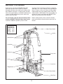
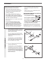
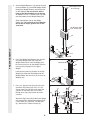
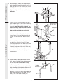
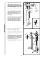
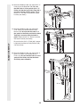
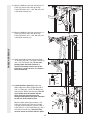
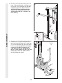
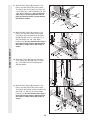
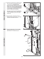
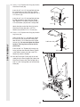
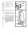
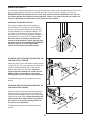
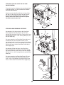
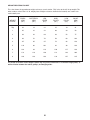
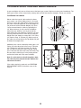
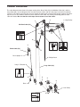
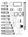
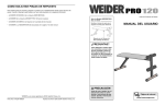
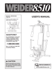
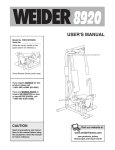
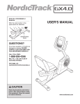
TM
Model No. WESY96252
Serial No.
(Write the serial number in the space
above for reference.)
Serial Number Decal
QUESTIONS?
As a manufacturer, we are committed to providing complete
customer satisfaction. If you have
questions, or find there are missing or damaged parts, we will
guarantee you complete satisfaction through direct assistance
from our factory.
TO AVOID UNNECESSARY
DELAYS, PLEASE CALL DIRECT
TO OUR TOLL-FREE CUSTOMER
HOT LINE. The trained technicians on our customer hot line
will provide immediate assistance, free of charge to you.
1-888-936-4266
CUSTOMER HOT LINE:
Mon.–Fri., 8 a.m.–6:30 p.m. EST
(excluding holidays)
CAUTION
Read all precautions and instructions in this manual before using
this equipment. Save this manual
for future reference.
USERʼS MANUAL
TABLE OF CONTENTS
IMPORTANT PRECAUTIONS . . . . . . . . . . . . . . . . . . . . . . . . . . . . . . . . . . . . . . . . . . . . . . . . . . . . . . . . . . . . . . . .2
BEFORE YOU BEGIN . . . . . . . . . . . . . . . . . . . . . . . . . . . . . . . . . . . . . . . . . . . . . . . . . . . . . . . . . . . . . . . . . . . . . .3
ASSEMBLY . . . . . . . . . . . . . . . . . . . . . . . . . . . . . . . . . . . . . . . . . . . . . . . . . . . . . . . . . . . . . . . . . . . . . . . . . . . . . . .4
ADJUSTMENT . . . . . . . . . . . . . . . . . . . . . . . . . . . . . . . . . . . . . . . . . . . . . . . . . . . . . . . . . . . . . . . . . . . . . . . . . . .19
TROUBLE-SHOOTING AND MAINTENANCE . . . . . . . . . . . . . . . . . . . . . . . . . . . . . . . . . . . . . . . . . . . . . . . . . . .22
LIMITED WARRANTY . . . . . . . . . . . . . . . . . . . . . . . . . . . . . . . . . . . . . . . . . . . . . . . . . . . . . . . . . . . . . . . . . . . . . .23
PART IDENTIFICATION CHART . . . . . . . . . . . . . . . . . . . . . . . . . . . . . . . . . . . . . . . . . . . . . . . . . . . .End of Manual
PART LIST . . . . . . . . . . . . . . . . . . . . . . . . . . . . . . . . . . . . . . . . . . . . . . . . . . . . . . . . . . . . . . . . . . . . .End of Manual
EXPLODED DRAWING . . . . . . . . . . . . . . . . . . . . . . . . . . . . . . . . . . . . . . . . . . . . . . . . . . . . . . . . . . .End of Manual
ORDERING REPLACEMENT PARTS . . . . . . . . . . . . . . . . . . . . . . . . . . . . . . . . . . . . . . . . . . . . . . . . . .Back Cover
IMPORTANT PRECAUTIONS
WARNING: To reduce the risk of serious injury, read the following important precautions before
using the home gym system.
1. It is the responsibility of the owner to ensure
that all users of the home gym system are
adequately informed of all precautions.
9. Always wear athletic shoes for foot protection when exercising.
10. Always stand on a foot plate when performing an exercise that could cause the home
gym system to tip.
2. Read all instructions in this manual and in
the accompanying literature before using the
home gym system.
11. Never release the press arm, butterfly arms,
squat arm, leg lever, lat bar, or nylon strap
while weights are raised. The weights will fall
with great force.
3. If you feel pain or dizziness at any time while
exercising, stop immediately and begin cooling down.
4. Use the home gym system only on a level
surface. Cover the floor or carpet beneath
the home gym system for protection.
12. Make sure that the cables remain on the pulleys at all times. If the cables bind while you
are exercising, stop immediately and make
sure that the cables are on all of the pulleys.
5. Inspect and tighten all parts often. Replace
any worn parts immediately.
13. Always disconnect the lat bar from the home
gym system when performing an exercise
that does not use the lat bar.
6. Keep small children and pets away from the
home gym system at all times.
14. The home gym system is intended for home
use only. Do not use the home gym system in
a commercial, rental, or institutional setting.
7. The home gym system is designed to be
used by only one person at a time.
8. Keep hands and feet away from moving
parts.
WARNING: Before beginning this or any exercise program, consult your physician. This is espe-
cially important for persons over the age of 35 or persons with pre-existing health problems. Read
all instructions before using. ICON assumes no responsibility for personal injury or property damage
sustained by or through the use of this product.
2
BEFORE YOU BEGIN
Customer Service Department toll-free at 1-888-9364266, Mon.–Fri., 8 a.m.–6:30 p.m. EST (excluding holidays). To help us assist you, please note the product
model number and serial number before calling. The
model number is WESY96252. The serial number can
be found on a decal attached to the WEIDER® PRO
9625 (see the front cover of this manual).
Thank you for selecting the WEIDER® PRO 9625
Home Gym System. The versatile PRO 9625 is
designed to develop every major muscle group of the
body. Whether your goal is a shapely figure, dramatic
muscle size and strength, or a healthier cardiovascular
system, the PRO 9625 will help you to achieve the
specific results you want.
For your benefit, read this manual carefully before
using the WEIDER® PRO 9625 Home Gym System.
If you have additional questions, please call our
Before reading further, please review the drawing
below and familiarize yourself with the parts that are
labeled.
ASSEMBLED
DIMENSIONS:
Height: 76 in.
Width: 38 in.
Length: 59 in.
High Pulley Station
Lat Bar
Butterfly Arms
Squat Arm
Backrests
Press Arm
Seats
Leg Lever
Weight Stack
Low Pulley Station
Foot Plate
3
ASSEMBLY
Before beginning assembly, carefully read the
following information and instructions:
• As you assemble the home gym system, be sure
that all parts are oriented as shown in the
drawings.
• Place all parts of the home gym system in a
cleared area and remove the packing materials;
do not dispose of the packing materials until
assembly is completed.
• Tighten all parts as you assemble them, unless
instructed to do otherwise.
THE FOLLOWING TOOLS (NOT INCLUDED) ARE
REQUIRED FOR ASSEMBLY:
• The assembly is divided into four stages: 1)
frame assembly, 2) press, squat, and butterfly
arm assembly, 3) cable and pulley assembly, and
4) seat and backrest assembly. The hardware for
each stage is packaged separately.
• Two (2) adjustable wrenches
• One (1) standard screwdriver
• One (1) phillips screwdriver
• Wait until you begin each assembly stage to open
that parts bag.
• One (1) rubber mallet
• For help identifying the small parts used in
assembly, use the PART IDENTIFICATION
CHART located in the center of this manual.
Note: Some small parts may have been preattached for shipping. If a part is not in the parts
bag, check to see if it has been pre-attached.
• Lubricant, such as grease or petroleum jelly,
and soapy water will also be needed.
Assembly will be more convenient if you have the
following tools: A socket set, a set of open-end or
closed-end wrenches, or a set of ratchet wrenches.
1. Before beginning assembly, be sure that
you have read and understand the information in the box above.
1
FRAME ASSEMBLY
Press a 2” Square Inner Cap (27) into the
end of the Rear Base (51). Press a 2” Square
Cover Cap (78) onto each end of the
Stabilizer (5).
27
51
11
Insert two 5/16” x 2 1/2” Carriage Bolts (1)
up through the Rear Base (51). Insert two
5/16” x 2 3/4” Bolts (11) through the Rear
Base and Stabilizer (5) as shown.
78
2. Press a 2” Square Inner Cap (27) into the
end of the Front Base (4).
Insert two 5/16” x 2 1/2” Carriage Bolts (1)
up through the Front Base (4). Slide the
Front Base onto the two 5/16” x 2 3/4” Bolts
(11) in the Rear Base (51) and Stabilizer (5).
Hand-tighten two 5/16” Nylon Locknuts (3)
onto the Carriage Bolts. Do not tighten the
Nylon Locknuts yet.
4
2
5
78
11
1
5
51
3
4
11
1
27
3. Press a 2” Square Inner Cap (27) into the
Rear Upright (56).
3
Attach a Rubber Bumper (90) to the Rear
Upright (56) with a #8 x 1/2” Tap Screw (89).
Slide the Rear Upright (56) onto the 5/16” x
2 1/2” Carriage Bolts (1) in the Rear Base
(51). Hand tighten a 5/16” Nylon Locknut (3)
onto each Carriage Bolt. The high side of
the bracket on the Rear Upright must be
on the side shown. Do not tighten the
Nylon Locknuts yet.
High Side of
Bracket
89
90
27
56
FRAME ASSEMBLY
3
51
1
4. Press a 1” Square Inner Cap (65) into the
Front Upright (42).
4
Slide the Front Upright (42) onto the 5/16” x
2 1/2” Carriage Bolts (1) in the Front Base
(4). Hand tighten a 5/16” Nylon Locknut (3)
onto each Carriage Bolt. Do not tighten the
Nylon Locknuts yet.
42
65
3
5
1
4
5. Set two Weight Bumpers (19) onto the bracket
on the Stabilizer (5). Insert both Weight Guides
through the Weight Bumpers and the bracket
on the Stabilizer. Be sure that the drilled
holes in the Weight Guides are at the top,
as shown. Press a 1” Round Cover Cap (70)
onto the bottom of each Weight Guide (62).
5
Drilled holes must
be at the top
62
Slide eight Weights (25) on the Weight
Guides (62). Be sure that all of the Weights
are turned so the pin grooves are on the
same side.
Pin Grooves must
be on this side
FRAME ASSEMBLY
25
19
70
6. Press the Weight Tube Bumper (64) into the
end of the Weight Tube (63). Insert the
Weight Tube into the stack of Weights (25).
Be sure that the pins on the Weight Tube are
resting in the pin grooves in the upper
Weight.
70
6
Pins
64
25
11
27
6
62
63
7
Attach the Top Frame (55) to the Front Upright
(42) and the Rear Upright (56) with four 5/16”
x 2 3/4” Bolts (11), four 5/16” Flat Washers
(8), and four 5/16” Nylon Locknuts (3).
76
Lubricate
Lubricate the insides of the holes in the Top
Weight (76). Slide the Top Weight onto the
Weight Guides (62) and set it on the stack of
Weights (25).
7. Press a 2” Square Inner Cap (27) into each
end of the Top Frame (55). Press a 1 3/4”
Square Inner Cap (44) into each end of the
crossbar on the Top Frame. Press two 1”
Round Inner Caps (49) into the top of the
crossbar.
5
55
3
11
8
8
49
44
Crossbar
44
56
27
3
42
27
FRAME ASSEMBLY
8. Attach the upper ends of the Weight Guides
(62) to the Top Frame (55) with the 5/16” x 6”
Bolt (60), two 1/2” x 3/4” Spacers (61), and a
5/16” Nylon Locknut (3).
8
55
Tighten all Nylon Locknuts used in steps 2
through 8.
9. Press a 1” x 7/8” Plastic Bushing (75) onto
each welded spacer on the Press Frame (17).
Slide the Press Frame into place on the Front
Base (4). Note: This will be a tight fit. The
Plastic Bushings should fit onto each end
of the indicated tube in the Base. Be sure
that the indicated holes are on the side
shown.
9
ARM ASSEMBLY
Assemble the other Press Arm (46) in the
same manner.
10
Attach a “V”-Pulley (6) and a Long Cable Trap
(50) to the Left Arm (47) with a 3/8” x 2 1/2”
Bolt (7) and a 3/8” Nylon Locknut (21).
7
Welded
Spacers
21
4
Tube
75
44
44
Welded
Brackets
48
49
46
49
11
Attach a “V”-Pulley (6) and a Long Cable Trap
(50) to the Right Arm (48) with a 3/8” x 2 1/2”
Bolt (7) and a 3/8” Nylon Locknut (21).
60
Lubricate
59
17
22
46
11. Identify the Right Arm (48) and the Left Arm
(47). Note the position of the welded bracket
on each Arm. Arm identification is very
important for step 12.
62
Holes must be
on this side
Lubricate the 3/8” x 8” Bolt (59). Attach the
Press Frame (17) to the Front Base (4) with
the 3/8” x 8” Bolt and a 3/8” Nylon Locknut
(21).
10. Press a 1 3/4” Square Inner Cap (44) into the
top of a Press Arm (46). Press a 1” Round
Inner Cap (49) into the side of the Press Arm.
Attach the Press Arm to one side of the Press
Frame (17) with two 5/16” x 2 1/2” Bolts (22)
and two 5/16” Nylon Locknuts (3).
61
3
50
7
3
17
50
6
21
47
12. Lubricate both axles on the Top Frame (55).
Slide the Right Arm (48) onto the right axle.
Note: Be careful not to confuse the Right
Arm with the Left Arm (47); refer to step 11
to identify the Right Arm. Be sure that the
upper end of the Right Arm is behind the
indicated bracket on the Top Frame (55).
Tap two 1” Retainers (69) and a 1” Round
Cover Cap (70) onto the right axle. Be sure
that the teeth on the Retainers bend
toward the Cover Cap, as shown in the
inset drawing.
Attach the Left Arm (47) in the same manner.
ARM ASSEMBLY
Press 1 3/4” Square Inner Caps (44) into the
lower ends of the Right and Left Arms (47,
48). Wet the lower end of each Arm with
soapy water. Slide a 10” Pad (45) onto the
lower end of each Arm.
12
Bracket
Lubricate
Axle
55
69
70
48
44
Axle
45
47
45
69
70
13. Press two 1” x 2” Inner Caps (83) into the
indicated end of the Squat Arm (79).
Lubricate a 3/8” x 3 1/4” Bolt (85). Attach the
Squat Arm (79) to the Front Upright (42) with
the 3/8” x 3 1/4” Bolt and a 3/8” Nylon
Locknut (21).
Attach a Handle (92) to one side of the Squat
Arm (79) with a 5/16” x 2 1/2” Bolt (22), two
5/16” Flat Washers (8), a 1/2” x 17/32” Spacer
(94), and a 5/16” Nylon Locknut (3).
Attach the other Handle (92) to the other side
of the Squat Arm (79) in the same manner.
13
83
92
22
94
8
3
8
83
8
94
8
22
92
3
21
79
42
85
Lubricate
8
14. During steps 15 through 36, refer to the
CABLE DIAGRAM attached to the PART ID
Chart to verify proper cable routing. Before
beginning this section, identify the Long Cable
(86), the Medium Cable (23), and the Short
Cable (58) by comparing the lengths and ends
of the cables.
14
86 (169”)
23 (155”)
IMPORTANT: While assembling the cables,
do not overtighten the bolts and nuts
securing the pulleys. The pulleys must be
able to turn freely.
58 (47”)
CABLE ASSEMBLY
15. Locate the Medium Cable (23). Wrap the
Medium Cable around a 3 1/2” Pulley (15).
Attach the Pulley to the Top Frame (55) with a
3/8” x 3 3/4” Bolt (71) and a 3/8” Nylon
Locknut (21). Be sure that the end of the
Cable with the ball is on the indicated side
of the Pulley and that the Cable is between
the Pulley and the hook.
15
21
15
Ball
Hook
16. Wrap the Medium Cable (23) around a “V”Pulley (6). Attach the “V”-Pulley and a Long
Cable Trap (50) to the indicated bracket on
the Front Upright (42) with a 3/8” x 2 1/2” Bolt
(7) and a 3/8” Nylon Locknut (21). Be sure
that the Long Cable Trap is positioned to
hold the Cable in place.
23
55
71
16
7
6
50
23
42
17. Route the Medium Cable (23) around the “V”Pulley (6) on the Left Arm (47). Be sure that
the Cable is in the groove of the Pulley and
that the Long Cable Trap (50) is positioned
to hold the Cable in place. Tighten the 3/8” x
2 1/2” Bolt (7) and the 3/8” Nylon Locknut (not
shown).
21
17
23
9
7
6
47
50
18. Route the Medium Cable (23) around the “V”Pulley (6) on the Right Arm (48). Be sure
that the Cable is in the groove of the “V”Pulley and that the Long Cable Trap (50) is
turned to hold the Cable in place. Tighten
the 3/8” x 2 1/2” Bolt (7) and the 3/8” Nylon
Locknut (not shown).
CABLE ASSEMBLY
19. Route the Medium Cable (23) around the
3 1/2” Pulley (15) attached to the Pulley
Bracket (20). Be sure that the Cable is in
the groove of the Pulley and that the Cable
Trap (66) is turned to hold the Cable in
place. Tighten the 3/8” x 2” Bolt (12) and the
3/8” Nylon Locknut (not shown).
18
6
50 48
19
68
20
66
Be sure that the 5/16” x 5” Bolt (68) is properly tightened and that the Pulley Bracket (20)
can move freely.
20. Route the Medium Cable (23) around one of
the 3 1/2” Pulleys (15) attached to the “I”
Plates (81). Be sure that the Cable is in the
groove of the Pulley and that the Cable
and Pulley move smoothly.
7
12
15
23
20
23
15
81
10
23
21. Wrap the Medium Cable (23) around a 3 1/2”
Pulley (15). Attach the Pulley to the Top
Frame (55) with a 3/8” x 1 3/4” Bolt (87) and
a 3/8” Nylon Locknut (21).
21
87
55
21
15
23
22. Wrap the Medium Cable (23) around a 3 1/2”
Pulley (15). Attach the Pulley to the Top
Frame (55) with a 3/8” x 1 3/4” Bolt (87) and
a 3/8” Nylon Locknut (21).
22
55
21
CABLE ASSEMBLY
87
15
23
23. Attach the Medium Cable (23) to the Small
“U”-Bracket (67) with a 1/4” Nylon Locknut (2)
and a 1/4” Flat Washer (10). Do not completely tighten the Nylon Locknut. It
should be threaded onto the end of the
Cable only a couple of turns, as shown in
the inset drawing.
23
23
10
2
24. Locate the Short Cable (58). Attach the
Short Cable to the Rear Upright (56) with a
5/16” x 3” Bolt (93), a 5/16” Flat Washer (8),
and two 5/16” Nylon Jam Nuts (84). The end
of the Cable must be between the two
Nylon Jam Nuts and there must be
enough room between the Nylon Jam Nuts
for the end of the Cable to pivot.
Wrap the Short Cable (58) around a 3 1/2”
Pulley (15). Attach the Pulley and a Cable
Trap (66) to the Squat Arm (79) with a 3/8” x
3 3/4” Bolt (71), a 3/8” Flat Washer (9), and a
3/8” Nylon Lock Nut (21). The Cable Trap
must be turned to hold the Cable in place.
11
23
24
67
10
2
67
21
9
79
66
71
58
15
56
84
8
93
25. Attach the end of the Short Cable (58) to the
Long “U”-Bracket (57) with a 1/4” Nylon Locknut (2) and a 1/4” Flat Washer (10). Do not
completely tighten the Nylon Locknut. It
should be threaded onto the end of the
Cable so only a couple of threads are
showing above the nut, as shown in the
inset drawing.
25
58
CABLE ASSEMBLY
57
58
10
2
26. Attach the 3 1/2” Low Pulley (88) and the 5/8”
x 9/16” Spacer (73) to the indicated hole in
the Press Frame (17) with a 3/8” x 3 3/4” Bolt
(71), a 3/8” Flat Washer (9), and a 3/8” Nylon
Locknut (21). Do not tighten the 3/8” Nylon
Locknut (21) yet. Be sure that the 3/8” x
3 3/4” Bolt (71), the 3/8” Flat Washer (9),
the 5/8” x 9/16” Spacer (73), the 3 1/2” Low
Pulley (88), and the 3/8” Nylon Locknut
(21) are oriented as shown.
26
2
57
9
21
12
10
17
71
73
88
27. Locate the Long Cable (86). Route the Long
Cable under the 3 1/2” Low Pulley (88). Be
sure that the end of the Cable with the ball
is on the indicated side of the Press Frame
(17) and that the Cable is between the
Pulley and the crossbar on the Press
Frame. Tighten the 3/8” Nylon Locknut (21)
and the 3/8” x 3 3/4” Bolt (not shown).
27
21
Ball
86
CABLE ASSEMBLY
28. Wrap the Long Cable (86) around a 3 1/2”
Pulley (15). Attach the Pulley and a Cable
Trap (66) to the lower hole in the Front
Upright (42) with a 3/8” x 3 3/4” Bolt (71), a
3/8” Flat Washer (9), and a 3/8” Nylon
Locknut (21). Be sure that the Cable Trap is
turned to hold the Cable in place and that
the Cable is routed around the Pulley as
shown.
29. Wrap the Long Cable (86) around a 3 1/2”
Pulley (15). Attach the Pulley and a Cable
Trap (66) to the Press Frame (17) with a 3/8”
x 3 1/2” Bolt (16), a 3/8” Flat Washer (9) and
a 3/8” Nylon Locknut (21). Be sure that the
Cable Trap is turned to hold the Cable in
place and that the Cable is routed around
the Pulley as shown.
Crossbar
17
28
21
66
86
15
71
9
42
29
86
15
9
30
13
6
42
21
16
21
17
30. Wrap the Long Cable (86) around a “V”-Pulley
(6). Attach the “V”-Pulley to the indicated hole
in the Front Upright (42) with a 3/8” x 3 1/4”
Bolt (85), a 3/8” Flat Washer (9), and a 3/8”
Nylon Locknut (21). Be sure that the Cable
is in the groove of the “V”-Pulley and that
the Cable is routed around the “V”-Pulley
as shown.
88
86
85
9
66
31. Wrap the Long Cable (86) around a 3 1/2”
Pulley (15). Attach the Pulley and a Cable
Trap (66) to the Press Frame (17) with a 3/8”
x 3 1/2” Bolt (16), a 3/8” Flat Washer (9), and
a 3/8” Nylon Locknut (21). Be sure that the
Cable Trap is turned to hold the Cable in
place and that the Cable is routed around
the Pulley as shown.
31
86
9
16
CABLE ASSEMBLY
32. Wrap the Long Cable (86) around a 3 1/2”
Pulley (15). Attach the Pulley and a Cable
Trap (66) to the indicated hole in the Front
Upright (42) with a 3/8” x 3 3/4” Bolt (71), a
3/8” Flat Washer (9), and a 3/8” Nylon
Locknut (21). Be sure that the Cable Trap is
turned to hold the Cable in place and that
the Cable is routed around the Pulley as
shown.
33. Route the Long Cable (86) over the lower
3 1/2” Pulley (15) attached to the “I”-Plates
(81). The Cable must be routed from the
direction shown.
42
86
9
15
71
66
81
15
86
14
34
86
12
66
17
32
33
34. Wrap the Long Cable (86) around a 3 1/2”
Pulley (15). Attach the Pulley and a Cable
Trap (66) to the bracket on the Front Base (4)
with a 3/8” x 2” Bolt (12) and a 3/8” Nylon
Locknut (21). Be sure that the Cable Trap is
turned to hold the Cable in place and that
the Cable is routed around the Pulley as
shown.
21
15
66
15
4
21
21
CABLE ASSEMBLY
35. Route the Long Cable (86) around the indicated 3 1/2” Pulley (15) and through the Long
“U”-Bracket (57). The Cable must be
between the Cable Trap (66) and the Pulley.
Tighten 3/8” x 2” Bolt (12) and the 3/8” Nylon
Locknut (not shown). Be sure that the Cable
is in the groove of the Pulley and that the
Cable and Pulley move smoothly.
35
57
66
12
15
Attach the end of the Long Cable (86) to the
Front Base (4) with a 5/16” x 2 3/4” Bolt (11),
a 5/16” Flat Washer (8), and a 5/16” Nylon
Locknut (3).
11
36. Attach the Small “U”-Bracket (67) to the
Weight Tube (63) with the 5/16” x 1 3/4” Bolt
(72) and a 5/16” Nylon Locknut (3).
86
4
8
36
67
72
37. Attach the Small Backrest (80) to the Rear
Upright (56) with two 1/4” x 2 1/2” Screws
(43) and two 1/4” Flat Washers (10).
3
63
SEAT ASSEMBLY
37
80
10
56
15
3
43
38. Press a 1 3/4” Square Inner Cap (44) into the
Rear Seat Frame (77).
Insert the 1/4” x 2 1/2” Carriage Bolt (91) into
the center hole in a Seat Plate (37). Attach
the Seat Plate to a Seat (13) with two 1/4” x
1/2” Screws (18).
38
91
44
Insert the 1/4” x 2 1/2” Carriage Bolt (91) into
the indicated hole in the Rear Seat Frame
(77). Tighten a 1/4” Nylon Locknut (2) with a
1/4” Flat Washer (10) onto the Carriage Bolt.
Attach the other end of the Seat (13) to the
Rear Seat Frame (77) with a 1/4” Flat Washer
(10) and the 1/4” x 2 1/4” Screw (82).
SEAT ASSEMBLY
39. Align the holes in the Rear Seat Frame (77)
with one set of holes in the Rear Upright (56).
Attach the Rear Seat Frame to the Rear
Upright with a 5/16” x 2 3/4” Carriage Bolt
(14) and a Seat Knob (40).
40. Attach the Large Backrest (41) to the Front
Upright (42) with two 1/4” x 2 1/2” Screws
(43) and two 1/4” Flat Washers (10). The
Backrest must be oriented as shown.
13
37
18
77
10
2
82
39
40
77
14
56
40
41
43 10
42
16
Thick End
41. Press a 1 1/2” Square Inner Cap (32) into the
Front Seat Frame (36).
Insert the 1/4” x 2 1/4” Carriage Bolt (38) into
the center hole in a Seat Plate (37). Attach
the Seat Plate to the Seat (13) with two 1/4” x
1/2” Screws (18).
41
13
37
Insert the 1/4” x 2 1/4” Carriage Bolt (38) into
the indicated hole in the Front Seat Frame
(36). Tighten a 1/4” Nylon Locknut (2) with a
1/4” Flat Washer (10) onto the Carriage Bolt.
Attach the other end of the Seat (13) to the
Front Seat Frame (36) with a 1/4” Flat
Washer (10) and the 1/4” x 2” Screw (24).
SEAT ASSEMBLY
42. Press a 1 1/2” Square Inner Cap (32) into the
Leg Lever (29).
42
Lubricate—33
43. Rest the Front Seat Frame (36) on the indicated pin in the Front Upright (42). Attach the
Front Seat Frame to the Front Upright with a
5/16” x 2 3/4” Carriage Bolt (14) and the Seat
Knob (40).
18
2
36
29
35
32
43
40
36
42
14
17
32
36
Lubricate the 5/16” x 2 1/4” Bolt (33). Attach
the Leg Lever (29) to the Seat Frame (36)
with the 5/16” x 2 1/4” Bolt and a 3/8” Nylon
Locknut (21). Do not overtighten the Nylon
Locknut. The Leg Lever must be able to
pivot freely.
Insert the 3/8” x 2” Eyebolt (35) into the Leg
Lever (29) from the direction shown. Tighten
a 3/8” Nylon Locknut (21) with a 3/8” Flat
Washer (9) onto the Eyebolt.
10
24
38
3
9
21
SEAT ASSEMBLY
44. Press 3/4” Round Inner Caps (34) into the
ends of both Pad Tubes (28).
Insert one Pad Tube (28) into the Front Seat
Frame (36). Slide a Foam Pad (30) onto each
end of the Pad Tube.
44
36
Insert the other Pad Tube (28) into the Leg
Lever (29). Slide a Foam Pad (30) onto each
end of the Pad Tube.
45. Remove the backing from the PRO 9625
decal and apply it to the home gym system as
shown.
28
34
30
34
30
29
45
MISC.
Make sure that all parts have been properly
tightened. The use of the remaining parts will
be explained in ADJUSTMENT, beginning on
page 19 of this manual.
Before using the home gym system, pull each
cable a few times to be sure that the cables
move smoothly over the pulleys. If one of the
cables does not move smoothly, find and correct the problem. IMPORTANT: If the cables
are not properly installed, they may be
damaged when heavy weight is used. See
the CABLE DIAGRAM attached to the
PART ID CHART for proper cable routing.
If there is any slack in the cables, you will
need to remove it by tightening the cables.
See TROUBLE-SHOOTING AND MAINTENANCE on page 22.
18
PRO 9625
ADJUSTMENT
The instructions below describe how each part of the home gym system can be adjusted. Refer to the exercise
poster accompanying this manual to see how the home gym system should be set up for each exercise.
IMPORTANT: When attaching the lat bar or nylon strap, make sure that the attachments are in the correct starting position for the exercise to be performed. If there is any slack in the cables or chain as an
exercise is performed, the effectiveness of the exercise will be reduced.
CHANGING THE WEIGHT SETTING
To change the weight setting of the weight stack,
insert a Weight Pin (26) under the desired Weight
(25). Be sure to insert the Weight Pin until the bent
end of the Weight Pin is touching the Weights, and
turn the bent end downward. The weight setting of
the weight stack can be changed from 6.5 pounds to
106.5 pounds, in increments of 12.5 pounds. Note:
Due to the cables and pulleys, the amount of
resistance at each exercise station may vary from
the weight setting. Use the WEIGHT RESISTANCE
CHART on page 21 to find the approximate
amount of resistance at each weight station.
25
26
ATTACHING THE LAT BAR OR NYLON STRAP TO
THE HIGH PULLEY STATION
Attach the Lat Bar (54) to the Medium Cable (23) with
a Cable Clip (53). For some exercises, the Chain (52)
should be attached between the Lat Bar and the
Medium Cable with two Cable Clips. Adjust the
length of the Chain between the Lat Bar and the
Medium Cable so the Lat Bar is in the correct
starting position for the exercise to be performed.
39
53
23
52
54
The Nylon Strap (39) can be attached in the same
manner.
ATTACHING THE LAT BAR OR NYLON STRAP TO
THE LOW PULLEY STATION
Attach the Lat Bar (54) to the Long Cable (86) with a
Cable Clip (53). For some exercises, the Chain (52)
should be attached between the Lat Bar and the Long
Cable with two Cable Clips. Adjust the length of the
Chain between the Lat Bar and the Long Cable so
the Lat Bar is in the correct starting position for
the exercise to be performed.
39
52
86
The Nylon Strap (39) can be attached in the same
manner.
19
53
54
ATTACHING THE LEG LEVER TO THE LOW
PULLEY STATION
53
To use the Leg Lever (29), the seat must be attached
to the front upright (see ATTACHING AND REMOVING THE SEATS below).
Attach one end of the Chain (52) to the Long Cable
(86) with a Cable Clip (53). Attach the other end of
the Chain to the Eyebolt (35) with a Cable Clip.
Always remove the Chain (52) from the Eyebolt
(35) before removing the seat.
52
35
86
ATTACHING AND REMOVING THE SEATS
29
A
See drawing A. Set the bracket on the Front Seat
Frame (36) onto the indicated pins on the Front
Upright (42). Attach the Front Seat Frame to the Front
Upright with the 5/16” x 2 3/4” Carriage Bolt (14) and
the Seat Knob (40).
36
For some exercises, the Front Seat Frame (36) must
be removed. First, be sure that the chain is not
attached to the leg lever. Next, remove the Seat Knob
(40) and the 5/16” x 2 3/4” Carriage Bolt (14) from the
Front Seat Frame. Lift the Front Seat Frame off the
Front Upright (42).
40
42
14
See drawing B. Align the holes in the Rear Seat
Frame (77) with one set of holes in the Rear Upright
(56). Attach the Rear Seat Frame to the Rear Upright
with the 5/16” x 2 3/4” Carriage Bolt (14) and the Seat
Knob (40).
B
For some exercises, the Rear Seat Frame (77) must
be removed. Remove the Seat Knob (40) and the
5/16” x 2 3/4” Carriage Bolt (14) from the Rear Seat
Frame. Lift the Seat Frame off the Rear Upright (56).
40
14
20
77
56
WEIGHT RESISTANCE CHART
This chart shows the approximate weight resistance at each station. “Top” refers to the 6.5 lb. top weight. The
other numbers refer to the 12.5 lb. weight plates. Weight resistance shown for the butterfly arm station is for
each butterfly arm.
WEIGHT
PLATES
PRESS
ARM
(lbs.)
BUTTERFLY
ARM
(lbs.)
LEG
LEVER
(lbs.)
HIGH
PULLEY
(lbs.)
LOW
PULLEY
(lbs.)
SQUAT
ARM
(lbs.)
Top
24
14
21
15
19
31
2
69
42
60
43
52
77
1
3
4
45
98
65
162
94
142
7
191
8
51
117
5
6
21
210
41
76
58
34
68
58
102
87
74
82
143
116
106
117
196
169
134
86
101
118
140
126
30
92
121
98
128
147
169
204
215
The actual resistance at each weight station may vary due to differences in individual weight plates, as
well as friction between the cables, pulleys, and weight guides.
21
TROUBLE-SHOOTING AND MAINTENANCE
Inspect and tighten all parts each time you use the home gym system. Replace any worn parts immediately. The
home gym system can be cleaned using a damp cloth and mild non-abrasive detergent. Do not use solvents.
TIGHTENING THE CABLES
1
Woven cable, the type of cable used on the home
gym system, can stretch slightly when it is first used.
If there is slack in the cables before resistance is felt,
the cables should be tightened. Insert the Weight Pin
(26) under one of the indicated Weights (25). Slack
can be removed from the cables by tightening the
1/4” Nylon Locknuts (2) at the end of the Medium
Cable (23) (see drawing 1) and at the end of the
Short Cable (58) (see drawing 2). To do this you may
need to remove the Small “U”-Bracket (67) from the
Weight Tube (not shown) or remove the 3 1/2” Pulley
(15) from the Long “U”-Bracket (57). Make sure that
the cables are not too tight or the Top Weight (76) will
be lifted off the weight stack.
23
67
2
25
26
Additional slack can be removed by moving the 3 1/2”
Pulley (15) to the other hole in the Long “U”-Bracket
(57). Remove the 3/8” Nylon Locknut (21) and the
3/8” x 2” Bolt (12) from the Cable Trap (66), Pulley,
and “U”-Bracket. Re-attach the Pulley and Cable Trap.
Be sure that the Cable trap is in the proper position
and that the Cable and Pulley move smoothly.
2
58
12
Note: If a cable tends to slip off the pulleys often,
the cable may have become twisted. Remove the
cable and re-install it.
66
If the cables need to be replaced, see ORDERING
REPLACEMENT PARTS on the back cover of this
manual.
22
57
76
21
2
15
86
LIMITED WARRANTY
ICON OF/DU CANADA INC., (ICON), warrants this product to be free from defects in workmanship and material, under normal use and service conditions, for a period of ninety (90) days from the date of purchase. This
warranty extends only to the original purchaser. ICON's obligation under this warranty is limited to replacing
or repairing, at ICON's option, the product at one of its authorized service centers. All products for which warranty claim is made must be received by ICON at one of its authorized service centers with all freight and other
transportation charges prepaid, accompanied by sufficient proof of purchase. All returns must be pre-authorized by ICON. This warranty does not extend to any product or damage to a product caused by or attributable to freight damage, abuse, misuse, improper or abnormal usage or repairs not provided by an ICON authorized service center, to products used for commercial or rental purposes, or to products used as store display
models. No other warranty beyond that specifically set forth above is authorized by ICON.
ICON is not responsible or liable for indirect, special or consequential damages arising out of or in connection
with the use or performance of the product or damages with respect to any economic loss, loss of property,
loss of revenues or profits, loss of enjoyment or use, costs of removal, installation or other consequential damages of whatsoever nature. Some provinces do not allow the exclusion or limitation of incidental or consequential damages. Accordingly, the above limitation may not apply to you. The warranty extended hereunder
is in lieu of any and all other warranties and any implied warranties of merchantability or fitness for a particular purpose is limited in its scope and duration to the terms set forth herein. Some provinces do not allow limitations on how long an implied warranty lasts. Accordingly, the above limitation may not apply to you.
The warranty extended hereunder is in lieu of any and all other warranties and any implied warranties of merchantability or fitness for a particular purpose is limited in its scope and duration to the terms set forth herein.
This warranty gives you specific legal rights. You may also have other rights which vary from province to
province or so specified by the retailer of your equipment.
ICON OF/DU CANADA, 900 de lʼIndustrie, St-Jérôme, QC J7Y 4B8
PLACE
STAMP
HERE
ICON of Canada Inc.
900 de lʼIndustrie
St-Jérôme, Québec
Canada, J7Y 4B8
23
CABLE DIAGRAM
The cable diagram below shows the proper routing of the Short Cable (58), the Medium Cable (23), and the
Long Cable (86). Use the diagram to be sure that the three cables and the cable traps have been assembled
correctly. If the cables have not been correctly routed, the home gym system will not function properly and damage may occur. The numbers show the correct route for each cable. The starting and ending points of each
cable are labeled. Be sure that the cable traps do not touch or bind the cables.
7
Medium Cable (23)
2
8
5
1—High Pulley
3
4
6
2
Short Cable (58)
7
Rear Upright—1
9—Weight Stack
Long “U”-Bracket—3
Long Cable (86)
9
Base—10
6
4
3
8
5
2
1—Low Pulley
REMOVE THIS PART IDENTIFICATION
CHART FROM THE MANUAL
This chart is provided to help you identify the small
parts used in assembly. Important: Some parts
may have been pre-assembled for shipping purposes. If you cannot find a part in the parts bags,
check to see if it has been pre-assembled. The
number in parenthesis below each part refers to the
key number of the part. The second number refers
to the quantity needed for assembly.
Please Note: The assembly is divided into four
stages: 1) frame assembly, 2) press, squat, and
butterfly arm assembly, 3) cable and pulley
assembly, and 4) seat and backrest assembly.
The hardware for each stage is packaged separately. Wait until you begin each assembly stage
to open that parts bag.
1" Square Inner Cap (65)—1
2" Square Cover Cap (78)–2
1 3/4" Square Inner Cap (44)–7
1 1/2" Square Inner Cap (32)—2
2" Square Inner Cap (27)–6
1" x 2" Endcap (83)–2
1/2" x 3/4" Spacer (61)–2
1 1/8" x 2 1/2" Plastic Bushing (74)–2
3/8" x 1 3/4" Bolt (87)–4
1/2" x 17/32" Spacer (94)–2
5/8" x 9/16" Spacer (73)–1
3/8" x 2" Bolt (12)–3
3/8" x 2 1/2" Bolt (7)–3
1" x 7/8" Plastic Bushing (75)–2
1" Retainer (69)–4
5/16" x 2 1/4" Bolt (33)–1
3/4" Round Inner Cap (34)–4
5/16" x 2 1/2" Bolt (22)–6
5/16" x 3" Bolt (93)–1
3/8" x 3 1/4" Bolt (85)–2
Cable Clip
(53)–2
1" Round Inner Cap (49)–6
3/8" x 3 1/2" Bolt (16)–2
3/8" x 3 3/4" Bolt (71)–5
1" Round Cover Cap (70)–4
3/8" x 8" Bolt (59)–1
5/16" x 1 3/4" Bolt (72)–1
1/4" Nylon Locknut (2)–4
1/4" x 2" Screw (24)–1
5/16" Nylon Jam Nut (84)–2
1/4" x 2 1/4" Carriage Bolt (38)–1
5/16" Nylon Locknut (3)–21
1/4" x 2 1/2" Screw (43)–4
3/8" Nylon Locknut (21)–21
1/4" x 2 1/2" Carriage Bolt (91)–1
1/4" Flat Washer (10)–10
1/4" x 2 1/4" Screw (82)–1
5/16" Flat Washer (8)–10
5/16" x 2 3/4" Bolt (11)–7
3/8" Flat Washer (9)–8
1/4" x 1/2" Screw (18)–4
#8 x 1/2" Self Tapping Screw (89)–1
5/16" x 2 1/2" Carriage Bolt (1)–4
5/16" x 2 3/4" Carriage Bolt (14)–2
5/16" x 5" Bolt (68)–1
5/16" x 6" Bolt (60)–1
PART LIST—Model No. WESY96252
Key No.
1
2
3
4
5
6
7
8
9
10
11
12
13
14
15
16
17
18
19
20
21
22
23
24
25
26
27
28
29
30
31
32
33
34
35
36
37
38
39
40
41
42
43
44
45
46
47
48
Qty.
4
4
21
1
1
4
3
10
8
10
7
5
2
2
13
2
1
4
2
1
21
6
1
1
8
1
6
2
1
4
6
2
1
4
1
1
2
1
1
2
1
1
4
7
2
2
1
1
Description
5/16” x 2 1/2” Carriage Bolt
1/4” Nylon Locknut
5/16” Nylon Locknut
Front Base
Stabilizer
“V”-Pulley
3/8” x 2 1/2” Bolt
5/16” Flat Washer
3/8” Flat Washer
1/4” Flat Washer
5/16” x 2 3/4” Bolt
3/8” x 2” Bolt
Seat
5/16” x 2 3/4” Carriage Bolt
3 1/2” Pulley
3/8” x 3 1/2” Bolt
Press Frame
1/4” x 1/2” Screw
Weight Bumper
Pulley Bracket
3/8” Nylon Locknut
5/16” x 2 1/2” Bolt
Medium Cable
1/4” x 2” Screw
Weight
Weight Pin
2” Square Inner Cap
Pad Tube
Leg Lever
Foam Pad
Hand Grip
1 1/2” Square Inner Cap
5/16” x 2 1/4” Bolt
3/4” Round Inner Cap
3/8” x 2” Eyebolt
Front Seat Frame
Seat Plate
1/4” x 2 1/4” Carriage Bolt
Nylon Strap
Seat Knob
Large Backrest
Front Upright
1/4” x 2 1/2” Screw
1 3/4” Square Inner Cap
10” Pad
Press Arm
Left Arm
Right Arm
Key No.
49
50
51
52
53
54
55
56
57
58
59
60
61
62
63
64
65
66
67
68
69
70
71
72
73
74
75
76
77
78
79
80
81
82
83
84
85
86
87
88
89
90
91
92
93
94
#
#
Qty.
6
3
1
1
2
1
1
1
1
1
1
1
2
2
1
1
1
8
1
1
4
4
5
1
1
2
2
1
1
2
1
1
2
1
2
2
2
1
2
1
1
1
1
2
1
2
1
1
Description
R0803A
1” Round Inner Cap
Long Cable Trap
Rear Base
Chain
Cable Clip
Lat Bar
Top Frame
Rear Upright
Long “U”-Bracket
Short Cable
3/8” x 8” Bolt
5/16” x 6” Bolt
1/2” x 3/4” Spacer
Weight Guide
Weight Tube
Weight Tube Bumper
1” Square Inner Cap
Cable Trap
Small “U”-Bracket
5/16” x 5” Bolt
1” Retainer
1” Round Cover Cap
3/8” x 3 3/4” Bolt
5/16” x 1 3/4” Bolt
5/8” x 9/16” Spacer
1 1/8” x 2 1/2” Plastic Bushing
1” x 7/8” Plastic Bushing
Top Weight
Rear Seat Frame
2” Square Cover Cap
Squat Arm
Small Backrest
“I” Plate
1/4” x 2 1/4” Screw
1” x 2” Inner Cap
5/16” Nylon Jam Nut
3/8” x 3 1/4” Bolt
Long Cable
3/8” x 1 3/4” Bolt
3 1/2” Low Pulley
#8 x 1/2” Tap Screw
Rubber Bumper
1/4” x 2 1/2” Carriage Bolt
Handle
5/16” x 3” Bolt
1/2” x 17/32” Spacer
Userʼs Manual
Exercise Poster
Note: “#” indicates a non-illustrated part. Specifications are subject to change without notice.
31
44
13
8
2
10
91
37
49
31
92
83
22
3
14
54
18
94
8
52
71
83
82
10
77
66
94
8
22
53
40
15
3
8
49
79
85
92
80
21
31
9
39
21
27
31
84
11
51
58
56
3
78
1
27
11
3
10
8
11
43
90
89
5
70
3
19
64
63
23
12
67
76
72
25
27
8
93
66
15 21
21 20 15
87
55
68
3
61
11
70
12
3
12
11
86
66
2
10
15
66
23
15
3
9
8
3
15
43 10
15
71
21
3
71
58 66
57
21
21
27
15 15
15 81
44
12
26
81
21
78
60
49
27 87
44
62
10
2
8
1
3
42
21
7
4
3
85 9
9
3
21
6
50
21
41
21
6
65
15
66
21
36 24
14
40
27
34
10
37
30
34
2 33
30
35
38
13
3
28
70
69
21
6
9
32
21
29
30
28
32
45
44
48
18
74
50
7
49
34
30
46
34
69
70
44
47
74
16
9
15
66
17
21
22
31
45
44
75
3
21
46
59
15
21 9
31
88
66
16
71
44
73
86
49
EXPLODED DRAWING—Model No. WESY96252
R0803A
ORDERING REPLACEMENT PARTS
To order replacement parts, simply call our Customer Service Department toll-free at 1-800-936-4266, Monday
through Friday, 8 a.m. until 6:30 p.m. EST (excluding holidays). To help us assist you, please be prepared to
give the following information:
1. The MODEL NUMBER of the product (WESY96252).
2. The NAME of the product (WEIDER® 9625 Home Gym System).
3. The SERIAL NUMBER of the product (see the front cover of this manual).
4. The KEY NUMBER and DESCRIPTION of the part(s) (see the PART LIST and EXPLODED DRAWING at the
center of this manual).
Part No. 185136 R0803A
Printed in Canada © 2003 ICON Health & Fitness, Inc.
™
®
of/du Canada Inc.
PRODUCT WARRANTY REGISTRATION
IMPORTANT: MAIL WITHIN 14 DAYS OF PURCHASE
NAME:
PHONE:
ADDRESS:
POSTCODE:
COUNTY:
MODEL NO.
SERIAL NO.
PURCHASE DATE:
RETAILER ADDRESS:
RETAILER NAME:
1) Primary user(s) of product:
Male
Female
2) Age of primary user:
0–24
25–34
35–44
45–54
3) Annual household income:
0–9,999
15,000–19,999
10,000–14,999
20,000+
Family
55–64
65 and over
4) How many times a week do you exercise?
Less than 3 times 3 times or more
5) Have you ever purchased an ICON product before?
Yes
No
6) Where did you first see or hear about ICON products?
Magazine
Friend/relative
Newspaper Ad
Store
Other
7) What was the primary reason for purchasing this ICON product?
Store Employee
Television Ads Colour
Electronic Features Magazine Ads Price
Product Design
Product Innovation
Other Features
8) Did you consider purchasing fitness equipment from another
manufacturer?
No
Yes
What other Manufacturer?
9) Based on your impression of what you have purchased,
would you buy another ICON product?
Yes
No
No Opinion
If not, what other brand name equipment would you purchase?
10) What other type of exercise equipment do you own?
Bicycle
Exercise Cycle Treadmill
Home Gym
Weight Bench Stepper
Cardio Glide
Other
11) Which type of magazines do you read regularly?
Sports
Fitness
Motoring
Business
Computer
General
12) Do you wish to be sent further bulletins about ICON products?
Yes
No
THANK YOU FOR YOUR TIME
© 2003 ICON of Canada, Inc. Printed in Canada