1
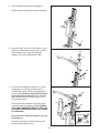
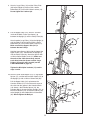
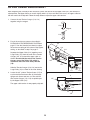
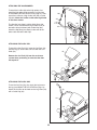
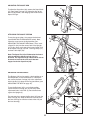
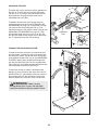
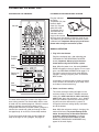
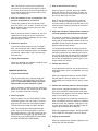
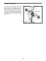
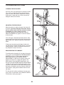
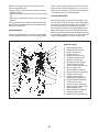
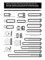
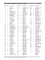
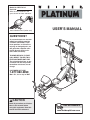
Model No. WESY78734
Serial No.
Write the serial number in the
space above for future reference.
Serial Number Decal (under seat)
USER’S MANUAL
QUESTIONS?
As a manufacturer, we are committed to providing complete
customer satisfaction. If you
have questions, or if there are
missing or damaged parts, we
will guarantee complete satisfaction through direct assistance from our factory.
TO AVOID DELAYS, PLEASE
CALL DIRECT TO OUR TOLLFREE CUSTOMER HOT LINE.
The trained technicians on our
customer hot line will provide
immediate assistance, free of
charge.
CUSTOMER HOT LINE:
1-877-992-5999
Mon.–Fri., 6 a.m.–6 p.m. MST
CAUTION
Read all precautions and instructions in this manual before
using this equipment. Save this
manual for future reference.
Visit our website at
www.weiderplatinum.com
TABLE OF CONTENTS
WARNING DECAL PLACEMENT . . . . . . . . . . . . . . . . . . . . . . . . . . . . . . . . . . . . . . . . . . . . . . . . . . . . . . . . . . . . . 3
IMPORTANT PRECAUTIONS . . . . . . . . . . . . . . . . . . . . . . . . . . . . . . . . . . . . . . . . . . . . . . . . . . . . . . . . . . . . . . . . 4
BEFORE YOU BEGIN . . . . . . . . . . . . . . . . . . . . . . . . . . . . . . . . . . . . . . . . . . . . . . . . . . . . . . . . . . . . . . . . . . . . . . 5
ASSEMBLY . . . . . . . . . . . . . . . . . . . . . . . . . . . . . . . . . . . . . . . . . . . . . . . . . . . . . . . . . . . . . . . . . . . . . . . . . . . . . . .6
UPPER CABLE ADJUSTMENT . . . . . . . . . . . . . . . . . . . . . . . . . . . . . . . . . . . . . . . . . . . . . . . . . . . . . . . . . . . . . .12
ADJUSTMENTS . . . . . . . . . . . . . . . . . . . . . . . . . . . . . . . . . . . . . . . . . . . . . . . . . . . . . . . . . . . . . . . . . . . . . . . . . . 13
CONSOLE OPERATION . . . . . . . . . . . . . . . . . . . . . . . . . . . . . . . . . . . . . . . . . . . . . . . . . . . . . . . . . . . . . . . . . . . .17
CABLE DIAGRAM . . . . . . . . . . . . . . . . . . . . . . . . . . . . . . . . . . . . . . . . . . . . . . . . . . . . . . . . . . . . . . . . . . . . . . . . .19
TROUBLESHOOTING . . . . . . . . . . . . . . . . . . . . . . . . . . . . . . . . . . . . . . . . . . . . . . . . . . . . . . . . . . . . . . . . . . . . .20
EXERCISE GUIDELINES . . . . . . . . . . . . . . . . . . . . . . . . . . . . . . . . . . . . . . . . . . . . . . . . . . . . . . . . . . . . . . . . . . 21
ORDERING REPLACEMENT PARTS . . . . . . . . . . . . . . . . . . . . . . . . . . . . . . . . . . . . . . . . . . . . . . . . . .Back Cover
LIMITED WARRANTY . . . . . . . . . . . . . . . . . . . . . . . . . . . . . . . . . . . . . . . . . . . . . . . . . . . . . . . . . . . . . . Back Cover
Note: A PART IDENTIFICATION CHART and a PART LIST/EXPLODED DRAWING are attached in the center of
this manual. Remove the PART IDENTIFICATION CHART and PART LIST/EXPLODED DRAWING before beginning assembly.
WEIDER is a registered trademark of ICON IP, Inc.
2
WARNING DECAL PLACEMENT
The decals shown here have been
placed on the resistance system. If a
decal is missing or illegible, please call
our Customer Service Department tollfree at 1-877-992-5999, Monday through
Friday, 6 a.m. until 6 p.m. Mountain
Time, to order a free replacement decal.
Apply the decal in the location shown.
Keep hands and
fingers clear of
this area.
3
IMPORTANT PRECAUTIONS
WARNING:
To reduce the risk of serious injury, read the following important precautions
before using the resistance system.
1. Read all instructions in this manual before
using the resistance system. Use the resistance system only as described in this manual.
11. The crossbar on the top frame is not
designed to be used for pull-up exercises. Do
not hang on the crossbar.
2. It is the responsibility of the owner to ensure
that all users of the resistance system are
adequately informed of all precautions.
12. Pull on the lower cable only while sitting on
the bench or standing on the base plate. Pull
on the high cables only while sitting on the
bench, with the seat in one of the three positions closest to the upright base, or while
standing on the base plate.
3. The resistance system is intended for home
use only. Do not use the resistance system in
any commercial, rental, or institutional setting.
13. The resistance system is designed to be
used with the included resistance. Do not
use the resistance system with any other
type of resistance.
4. Use the resistance system only on a level
surface. Cover the floor beneath the resistance system to protect the floor.
5. Keep the resistance system indoors, away
from moisture and dust. Do not put the
resistance system in a garage or covered
patio, or near water.
13. Always disconnect the lat bar from the high
cables when performing an exercise that
does not require it.
14. Make sure the storage knob is in place and
fully tightened each time the resistance system is used.
6. Make sure that all parts are properly tightened each time the resistance system is
used. Replace any worn parts immediately.
8. Keep hands and feet away from moving parts.
15. Make sure that the cables remain on the pulleys at all times. If the cables bind as you are
exercising, stop immediately and make sure
that the cables are on the pulleys. Replace all
cables at least every two years.
9. Always wear athletic shoes for foot protection while exercising.
16. Do not pull on the cables while the resistance level is being adjusted.
10. The resistance system is designed to support a maximum user weight of 300 pounds.
17. If you feel pain or dizziness while exercising,
stop immediately and begin cooling down.
7. Keep children under 12 and pets away from
the resistance system at all times.
WARNING:
Before beginning this or any exercise program, consult your physician. This
is especially important for persons over the age of 35 or persons with pre-existing health problems.
Read all instructions before using. ICON assumes no responsibility for personal injury or property
damage sustained by or through the use of this product.
4
BEFORE YOU BEGIN
Thank you for selecting the innovative WEIDER® PLATINUM resistance system. The resistance system offers
a selection of stations designed to develop every major
muscle group of the body. Whether your goal is to tone
your body, build dramatic muscle size and strength, or
improve your cardiovascular system, the resistance system will help you to achieve the specific results you
want.
after reading this manual, please call our Customer
Service Department toll-free at 1-877-992-5999,
Monday through Friday, 6 a.m. until 6 p.m. Mountain
Time (excluding holidays). To help us assist you, please
note the product model number and serial number
before calling. The model number is WESY78734. The
serial number can be found on a decal attached to the
resistance system (see the front cover of this manual).
For your benefit, read this manual carefully before
using the resistance system. If you have questions
Before reading further, please review the drawing below
and familiarize yourself with the parts that are labeled.
Crossbar
Top Frame
Lat Bar
Console
High Pulley
Resistance Bar
Squat Backrest
Squat Pin
Backrest
Storage Knob
Low Pulley
Curl Pad
Row Plate
Seat
Seat Knob
Curl Bar
Base Plate
ASSEMBLED
DIMENSIONS:
Height: 86 in.
Width: 50 in.
Depth: 85 in.
Leg Lever
5
ASSEMBLY
• Tighten all parts as you assemble them, unless
instructed to do otherwise.
Make Things Easier for Yourself
This manual is designed to ensure that the resistance system can be assembled successfully by
most people. However, it is important to realize
that the versatile resistance system has many
parts and that the assembly process will take
time. Most people find that by setting aside plenty
of time, assembly will go smoothly.
• As you assemble the resistance system, make
sure all parts are oriented as shown in the drawings.
The included Allen wrenches
and the following tools (not included) are required for
assembly:
Before beginning assembly, carefully read the
following information and instructions:
• Two adjustable wrenches
• Assembly requires two persons.
• One standard screwdriver
• One rubber mallet
• Place all parts in a cleared area and remove the
packing materials. Do not dispose of the packing
materials until assembly is completed.
• One Phillips screwdriver
• Lubricant, such as grease or petroleum jelly,
and soapy water.
• For help identifying small parts, use the PART
IDENTIFICATION CHART. Note: Some small
parts may have been pre-attached for shipping. If
a part is not in the parts bag, check to see if it
has been pre-attached.
1.
Assembly will be more convenient if you have a
socket set, a set of open-end or closed-end
wrenches, or a set of ratchet wrenches.
1
Before beginning assembly, make sure that
you have read and understand the information in the box above. Refer to the PART
IDENTIFICATION CHART for help identifying
small parts.
2
Pull the lower end of the Upper Wire Harness
(71) out of the hole in the back of the Upright (2).
71
Attach the Upright (2) to the Base Plate (1) with
an M10 x 25mm Button Screw (88), an M10
Washer (106), an M10 x 92mm Button Bolt (83),
and an M10 Nylon Locknut (103).
88
106
103
83
1
6
2. Insert the connector of the Upper Wire Harness
(71) into the socket of the Lower Wire Harness
(143). The connector should slide easily into
the socket and snap into place. If the connector
does not slide easily and snap into place, turn it
over and then insert it.
2
6
12
85
Make sure that the connector and wires appear
as shown in the inset drawing. IF THE CONNECTOR IS NOT INSERTED PROPERLY, THE CONSOLE MAY BE DAMAGED WHEN THE POWER
IS TURNED ON.
143
71
Insert the Mech Frame (6) into the Base Plate (1).
Attach the Mech Frame to the Upright (2) with a
1/2” x 25mm Screw (85) and a 1/2” Lock Washer
(12). Do not tighten the Screw yet.
103
Attach the Mech Frame (6) to the Base Plate (1)
with four M10 Nylon Locknuts (103).
Black
Wire
2
1
Tighten the 1/2” x 25mm Screw (85).
143
103
71
3. Press the Rail Cap (49) onto the Leg (5). Attach
the Leg to the Rail (4) with two M10 x 64mm
Button Bolts (80), four M10 Washers (106), and
two M10 Nylon Locknuts (103).
Red
Wire
3
103
106
4
Holes on
this side
106
49
80
5
4. Lubricate an M10 x 125mm Button Bolt (89) with
grease. Attach the Rail (4) to the Row Plate (28)
with the Bolt, two M10 Washers (106), two 31mm
Spacers (30), and an M10 Nylon Locknut (103).
Do not overtighten the Locknut; the Rail must
be able to pivot easily.
4
29
28
103 106
Tighten the Storage Knob (29) into the Row Plate
(28) and the Rail (4).
30
4
30
106
Lubricate
7
89
5. Insert the Squat Pin (66) into the Upright (2).
5
Slide the Squat Carriage (19) onto the Upright (2).
2
19
66
6. Attach the Top Frame (37) to the Upright (2) with
two M10 x 25mm Button Screws (88), an M10 x
75mm Button Screw (84), three M10 Lock
Washers (75), and an M10 Washer (106).
6
88
37
75
84
2
75
106
7. Pull the excess Upper Wire Harness (71) out of
the Upright (2). Insert the connector on the
Console (67) into the socket on the Upper Wire
Harness. The connector should slide easily into
the socket and snap into place. If the connector
does not slide easily and snap into place, turn it
over and then insert it.
7
114
71
2
67
Make sure that the connector and wires appear
as shown in the inset drawing. IF THE CONNECTOR IS NOT INSERTED PROPERLY, THE CONSOLE MAY BE DAMAGED WHEN THE POWER
IS TURNED ON.
114
Black
Wire
Push the excess Upper Wire Harness (71) into
the Upright (2).
143
Attach the Console (67) to the Upright (2) with
four M4 x 70mm Screws (114).
71
8
Red
Wire
8. Attach a Large Pulley (14) and the Pulley Plate
(68) to the Upright (2) with an M12 x 62mm
Button Bolt (81) and an M12 Nylon Locknut (13).
Do not tighten the Locknut yet.
8
68
13
14
2
81
9. Pull the Upper Cable (121), which is attached
inside of the Mech Frame (not shown), up
between the Upright (2) and the Pulley Plate (68).
9
Attach another Large Pulley (14) to the Upright (2)
and the Pulley Plate (68) with an M12 x 62mm
Button Bolt (81) and an M12 Nylon Locknut (13).
Make sure that the Upper Cable (121) is
between the two Pulleys.
11
90
121
13
68
81
Hold the 38mm Spacer (90) inside the loop of the
Upper Cable (121), and between the Upright (2)
and the Pulley Plate (68). Attach the Spacer with
an M10 x 58mm Button Screw (11). Make sure
the ends of the Cable do not wrap around
each other below the Spacer and the Large
Pulleys (14) used in steps 8 and 9 (see the
CABLE DIAGRAM on page 19).
14
2
Tighten the M12 Nylon Locknuts (13) used in
steps 8 and 9.
10. Attach a Small Guide Spacer (18), a Large Guide
Spacer (17), and the two Crossbar Guides (15) to
the Upright (2) with an M10 x 152mm Bolt (86).
10
Pull the Upper Cable (121) up between the
Crossbar Guides (15). Press the metal cover on
the cable into the groove in the Crossbar Block
(16). Attach a Small Guide Spacer (18), the
Crossbar Block, the two Crossbar Guides (15), an
M10 Thick Washer (54), and the two Tethers (70)
to the Upright (2) with another M10 x 152mm Bolt
(86). Do not tighten the Bolt yet.
17
18
86
15
2
121
Metal
Cover
54
86
70
18
9
16
Groove
11. Insert the Resistance Bar (9) between the
Crossbar Guides (15), and center it on the
Crossbar Block (not shown).
11
15
70
Press a Pulley Bracket (10) onto the Resistance
Bar (9). Screw a 3/8” x 38mm Tension Screw
(117) into the Pulley Bracket a couple of turns.
Make sure the hexagonal hole in the Screw is
on the outside of the Bracket.
54
103
9
Attach a Tether (70) to the Pulley Bracket (10) at
the upper hole with an M10 x 64mm Button Bolt
(80), an M10 Thick Washer (54), and an M10 Nylon
Locknut (103).
10
80
117
Repeat this step on the other side of the
Resistance Bar (9). Then, tighten the lower
M10 x 152mm Bolt (86) used in step 10.
12
13
12. Hold a Large Pulley (14) inside of the Upper
Cable (121). Attach the Pulley to a Pulley Bracket
(10) with an M12 x 58mm Button Bolt (87) and an
M12 Nylon Locknut (13). Make sure that the
cable is routed as shown in the CABLE DIAGRAM on page 19.
10
87
14
121
13. Hold a Large Pulley (14) inside the Upper Cable
(121). Attach the Pulley to the other Pulley
Bracket (10) with an M12 x 58mm Button Bolt
(87) and an M12 Nylon Locknut (13). Make sure
that the cable is routed as shown in the
CABLE DIAGRAM on page 19.
13
13
Tighten the two 3/8” x 38mm Tension Screws
(117) an equal number of turns.
117
121
10
87
14. Attach the Leg Lever (56) to the Leg (5) with a
Leg Station Pin (60). Slide a Cotter Pin (113) onto
the Leg Station Pin.
14
14
5
56
113
60
10
15. Slide a Pad Tube (50) into the Leg Lever (56).
Slide two Large Foam Pads (52) onto the Pad
Tube.
15
5
Attach the other two Pad Tubes (50) to the Leg
Lever (56) and the Leg (5) in the same manner.
50
56
52
50
52
50
16. Insert the rod on the Backrest Frame (32) into the
slot in the Seat Carriage (44). Hold the Backrest
Frame vertically over the Seat Carriage and
slide the rod into the slot, as shown in the
inset drawing.
16
32
Rod
Slot
44
32
44
17. Attach the Curl Pad (43) to the Curl Post (42) with
two M6 x 16mm Screws (41).
17
43
18. Adjust the tension on the upper cable (not shown)
as described in UPPER CABLE ADJUSTMENT
on page 12.
19. Make sure that all parts have been properly tightened. The use of the remaining parts will be
explained in ADJUSTMENTS, beginning on page
13.
42
Before using the resistance system, turn on
the console and change the resistance setting
as described in CONSOLE OPERATION on
page 17.
41
11
UPPER CABLE ADJUSTMENT
After completing the assembly of the resistance system, the tension on the Upper Cable (121) will need to be
adjusted. Also, the Upper Cable can stretch slightly when it is first used. When this occurs, the upper cable tension will need to be readjusted. Follow the steps below to adjust the upper cable tension.
1. Connect the two Tension Gauges (118, 119)
together using the magnet.
1
118
Magnet
119
2. Plug in the resistance system as described in
PLUGGING IN THE RESISTANCE SYSTEM on
page 17. Use the Console (not shown) to adjust
the resistance setting of the system to the highest
setting, as described in step 2 on page 17.
2
10
118
121
Squeeze the Upper Cable (121) together near a
Large Pulley (14). Hook the ends of the Tension
Gauges (118, 119) around the upper cable as
shown. Do not hook the ends of the Tension
Gauges around the Tether (70), which is
attached to the back of the Pulley Bracket
(10).
119
14
70
121
Slide the Tension Gauges (118, 119) next to the
Large Pulley (14) as shown in the inset drawing.
118
14
3. Locate the 3/8” x 38mm Tension Screw (117) on
each end of the Resistance Bar (9). Alternately
tighten each Screw one turn at a time until the
two Tension Gauges (118, 119) are pulled apart
by the Upper Cable (121).
3
9
117
The upper cable tension is now properly adjusted.
118
119
121
12
119 121
ADJUSTMENTS
This section explains how to adjust the resistance system. See the EXERCISE GUIDELINES on page 21 for
important information about how to get the most benefit from your exercise program. Also, see the accompanying exercise guide to see the correct form for each exercise.
Make sure all parts are properly tightened each time the resistance system is used. Replace worn parts immediately. The resistance system can be cleaned with a damp cloth and a mild, non-abrasive detergent. Do not use
solvents. The resistance bar can be cleaned with a vinyl and rubber protectant, available at an automotive or
department store.
ATTACHING THE HIGH PULLEYS
37
To use a high pulley, slide the hook on the Pulley
Housing (39) onto a hook on the Top Frame (37).
Attach the end of the High Cable (101) without the
ball to the end of the Lower Cable (120) with a Cable
Clip (94). Attach the other high pulley in the same
manner.
39
Ball
Remove the high pulleys when not in use.
101
USING THE LEG LEVER
To use the Leg Lever (56), attach it to the Leg (5) with
a Leg Station Pin (60). Slide a Cotter Pin (113) onto
the Leg Station Pin.
120
Route the hook end of the Leg Lever Cable (102)
under the 90mm Pulley (40) in the Leg (5), and attach
it to the Leg Lever (56). Make sure the hook is oriented as shown when attaching it to the Leg
Lever. Insert a Leg Station Pin (60) into the Leg,
under the Cable. Slide a Cotter Pin (113) onto the Leg
Station Pin.
94
50
56
52
113
55
See the inset drawing. Attach a long end of the Leg
Lever Cable (102) to one end of the Lower Cable
(120) with a Cable Clip (94). Attach the other long
end of the Leg Lever Cable to the other end of the
low cable in the same manner.
5
40
102
113
60
To perform the leg extension exercise, the indicated Pad Tube (50) should be inserted through the Leg
(5) as shown.
Hook
To perform the leg curl exercise, remove a Large
Foam Pad (52) from the indicated Pad Tube (50).
Remove the Pad Tube and insert it through the hole
in the Leg Lever Bumper (55).
102
94
120
13
60
ATTACHING THE ACCESSORIES
To attach the Lat Bar (82) to the high pulleys, first
attach the high pulley to the resistance system (see
ATTACHING THE HIGH PULLEYS on page 13). Then,
attach the Lat Bar to a High Cable (101) with a Cable
Clip (94). Attach the Lat Bar to the other High Cable
in the same manner.
101
94
101
The Handles (not shown) and the Ankle Strap (not
shown) can be attached to the High Cables (101) or
the lower cable (not shown) with Cable Clips (94).
Attach the Hip Strap (not shown) to the ends of the
lower cable with two Cable Clips.
82
ATTACHING THE CURL PAD
To attach the Curl Pad (43), insert the Curl Post (42)
into the Leg (5). Secure the Curl Post with the Curl
Knob (59).
43
Remove the Curl Pad (43) from the resistance
system when performing an exercise that does
not require it.
42
5
ATTACHING THE CURL BAR
To use the Curl Bar (53), first attach the leg lever to
the leg (see USING THE LEG LEVER on page 13).
Attach the Curl Bar to the hook on the Leg Lever (56)
with a Cable Clip (94).
53
94
56
14
59
ADJUSTING THE SQUAT ARM
27
To adjust the Squat Arm (20), remove the Squat Knob
(27) from Squat Carriage (19). Move the Arm to the
low or high position, and reengage the Knob into the
Squat Carriage.
19
20
ATTACHING THE SQUAT STATION
To use the squat station, first remove the backrest
(see ADJUSTING THE BACKREST below). Next,
adjust the squat arm to the high position (see
ADJUSTING THE SQUAT ARM above). Then, insert
a Squat Pin (66) into the correct hole in the Upright
(2). Finally, attach each end of the Lower Cable (121)
to the Squat Carriage (19) with a Carriage Strap (77)
and two Cable Clips (94).
20
94
Note: The Squat Pin (66) will determine the lowest
point to which the Squat Carriage (19) can
descend. The Squat Carriage should not be able to
descend so low that the user could become
trapped under the Squat Arm (20).
19
2
77
66
94
121
ADJUSTING THE BACKREST
35
The Backrest (35) can be used in a level position or an
inclined position. To use the Backrest in a level position, secure the Seat Carriage (44) at the adjustment
hole in the Rail (4) closest to the Leg (not shown) (see
ADJUSTING THE SEAT on page 16).
2
To use the Backrest (35) in an inclined position,
secure the Seat Carriage (44) at one of the other
adjustment holes in the Rail (4). Rest the Backrest
against the Upright (2).
For row exercises, remove the Backrest (35) from the
Seat Carriage (44). Hold the Backrest vertically over
the Seat Carriage and lift the rod out of the slot (see
the inset drawing).
4
Rod
32
44
Slot
44
15
ADJUSTING THE SEAT
45
The Seat (45) can be secured at various positions on
the Rail (4). To move the Seat, pull the Seat Knob
(48) out as far as it will go and slide the Seat to the
desired position. Engage the Seat Knob into an
adjustment hole in the Rail.
35
4
To perform row exercises, the hip strap must be
attached to the mech cable (see ATTACHING THE
ACCESSORIES on page 14), and the Seat Carriage
(44) must be able to roll along the Rail (4). First,
remove the Backrest (35) from the Seat Carriage (see
ADJUSTING THE BACKREST on page 15). Then,
pull the Seat Knob (48) out as far as it will go, and
turn the Seat Knob so that the pin rests at the end of
the “L”-shaped slot (see the inset drawing).
44
48
Adjustment
Hole
Pin
44
“L”-Slot
48
STORING THE RESISTANCE SYSTEM
37
To store the resistance system, first remove the Curl
Pad (not shown) and the Leg Lever (not shown) from
the resistance system. Secure the Seat Carriage (44)
at the position closest to the Leg (5) (see ADJUSTING
THE SEAT above). Next, remove the Storage Knob
(29) from the Row Plate (28). Lift the Leg toward the
Top Frame (37), and tighten the Storage Knob into the
side of the Row Plate and into the Rail (4).
Hold in
this area
5
44
To move the resistance system, stand behind the
Upright (2), place the toe of your shoe on the end of
the Base Plate (1), and hold the resistance system in
the indicated area. Tilt the resistance system back
onto the Wheels (65) and roll it to the new location.
2
WARNING:
Make sure that
Storage Knob (29) is in place and fully tightened each time the resistance system is used.
4
28
65
29
1
16
CONSOLE OPERATION
FEATURES OF THE CONSOLE
Console
PLUGGING IN THE RESISTANCE SYSTEM
Plug the indicated
end of the
Transformer (72) into
the Back Mech
Cover (8). Plug the
other end of the
Transformer into a
8
120-volt outlet. All
72
indicators and displays on the console
will flash once; the console will then be ready for use.
The motor may be heard while the resistance system
calibrates itself. Important: Always plug in the transformer when using the resistance system.
MANUAL OPERATION
1. Plug in the transformer.
Program
Buttons
Plug the transformer into a 120-volt outlet (see
PLUGGING IN THE RESISTANCE SYSTEM
above). Important: Always plug in the transformer when using the resistance system.
Main
Display
Note: When the power is on, the words MANUAL
MODE will appear in the main display. To use a program, see PROGRAM OPERATION on page 18. If
you want to return to the manual mode while the
console is running a program, press and hold the
NEXT button.
Resistance
Display
If no buttons are pressed and no cables are pulled
for ten minutes, the console will go to sleep. Press
any button to resume exercising.
Sets
Display
Reps
Display
2. Select a resistance setting.
The current resistance setting will appear in the
resistance display. To select a different resistance
setting, first make sure that no cables are being
pulled. Next, press the resistance + and – buttons.
Each time a button is pressed, the resistance setting will increase or decrease by 1 pound. To
change the resistance setting quickly, hold down
one of the buttons.
The heart of the resistance system is the digital resistance training console. The console offers both a manual mode and nine workout programs. When the manual
mode is selected, the resistance setting can be
changed with the touch of a button. When a program is
selected, the console will guide you through an effective upper body, ab and back, or lower body workout.
Note: While the resistance setting is changing, the
motor will be heard. To prevent damage to the
motor, do not pull any of the cables while the
resistance setting is changing. If a cable is
pulled, the words RELEASE HANDLES AND
READJUST RESISTANCE AS DESIRED may
appear in the main display.
To use the manual mode of the console, follow the
steps at the right. To use a program, see page 18.
17
Note: The resistance system uses progressive
resistance. As the resistance bar begins to bend,
the amount of resistance will increase gradually. As
the bar bends further, the resistance will increase
rapidly, up to 340 pounds.
3. Row for five minutes to warm up.
When a program is selected, the words CARDIO
ROW will appear in the main display. To warm up,
perform the cardio row exercise while the main display counts down from 5 minutes.
3. Enter the numbers of sets and repetitions that
you plan to complete for an exercise.
Note: To see the correct form for the cardio row
exercise, see the included exercise guide. If the
resistance setting is too high or too low, select a different resistance setting by pressing the resistance
+ and – buttons.
To enter the number of sets that you plan to do,
press the SETS + and – buttons. To enter the number of repetitions that you plan to do, press the
REPS + and – buttons.
Note: If you do not enter the numbers of sets and
repetitions that you plan to do, the console will
count the total number of repetitions that you complete during your workout.
4. Adjust the resistance setting and the numbers of
sets and repetitions for the exercise if desired.
The name of an exercise in the program will appear
in the main display. The recommended resistance
setting and the recommended numbers of sets and
repetitions for the exercise will appear in the three
displays below the main display.
4. Perform the exercise.
If you have entered numbers of sets and repetitions, the console will count down the repetitions
and sets you have completed. When you complete
the exercise, repeat steps 2 and 3 above for the
next exercises.
The recommended resistance setting and the recommended numbers of sets and repetitions may be
too high or too low for you, depending on such factors as your body size and your physical condition. If
desired, adjust the resistance setting and the numbers of sets and repetitions by pressing the + and –
buttons below each display.
5. Unplug the transformer.
When you complete your workout, unplug the transformer from the 120-volt outlet.
5. Perform the exercise.
As you perform the exercise, the console will count
down the numbers of sets and repetitions you have
completed.
PROGRAM OPERATION
1. Plug in the transformer.
When you complete the exercise, the word RESTING will appear in the main display. It is recommended that you rest while the main display counts
down.
Plug the transformer into a 120-volt outlet (see
PLUGGING IN THE RESISTANCE SYSTEM on
page 17). Important: Always plug in the transformer when using the resistance system.
6. Perform the remaining exercises in the program.
Note: If no buttons are pressed and no cables are
pulled for ten minutes, the console will go to sleep.
Press any button to resume exercising.
After you have completed an exercise in the program, press the NEXT button and the name of the
next exercise will appear in the main display. Repeat
steps 4 and 5 above for the exercise.
2. Select a program.
Note: The program may include the same exercise
twice, with different resistance settings and different
numbers of sets and repetitions. If you wish to skip
any part of the program, press the NEXT button to
advance to the next part of the program.
When the power is on, the words SELECT PROGRAM will appear in the main display. To select a
program, press one of the nine program buttons.
The indicator on the button you press will light.
Note: The console offers three upper body programs, three ab and back programs, and three
lower body programs. If you wish to exercise your
upper body and if your goal is to lose weight, for
example, press the LOSE WEIGHT button below
the words UPPER BODY PROGRAMS.
When you complete the program, the words WORKOUT COMPLETE will appear in the main display.
7. Unplug the transformer.
When you complete your workout, unplug the transformer from the 120-volt outlet.
18
CABLE DIAGRAM
The cable diagram shows the proper routing of the
Upper Cable (121). Use the diagram to make sure
that the cable has been assembled correctly. If the
cable has not been correctly routed, the resistance
system will not function properly and damage may
occur. The numbers show the correct route for the
cable. Make sure that the ends of the cable do not
wrap around each other between positions 1 and
2, and 5 and 6.
Upper Cable (121)
4
5
2
6
19
1
3
TROUBLESHOOTING
CLEANING THE BAR GUIDES
Over time, dust may build up on the Crossbar Guides
(15), causing a squeaking noise as the resistance
system is used. If this occurs, wipe off the Crossbar
Guides with a damp cloth and a mild, non-abrasive
detergent. Do not use solvents.
15
ADJUSTING THE RESISTANCE
When the resistance setting changes, the motor will
be heard. To prevent damage to the motor, do not
pull any of the cables while the resistance setting
is changing. If a cable is pulled, the words
RELEASE HANDLES AND READJUST RESISTANCE AS DESIRED may appear in the main display
on the console.
If this message is displayed repeatedly but no cable
is being pulled, there may be too much tension on the
Upper Cable (121). Adjust the tension as described
below.
To decrease the tension on the Upper Cable (121),
turn the two 3/8” x 38mm Tension Screws (117) twice,
counterclockwise. Select the desired resistance setting. Repeat this step if necessary.
121
RECALIBRATING THE CONSOLE
To recalibrate the Console (67), first plug in the resistance system (see PLUGGING IN THE RESISTANCE
SYSTEM on page 17). Then, press and hold the
NEXT button and the MOTORIZED WEIGHT
ADJUSTMENT + button for five seconds. When the
buttons are released, a number will appear in the
REPS display. Press the NEXT button again, and
then press the MOTORIZED WEIGHT ADJUSTMENT
+ button; this will start the recalibration process. This
may take a few minutes as the motor moves between
the lowest and highest resistance settings. When the
motor finishes, unplug the transformer from the 120volt outlet.
67
The Console (67) will be recalibrated. Use the resistance system as described in the CONSOLE OPERATION section, starting on page 17.
20
117
EXERCISE GUIDELINES
THE FOUR BASIC TYPES OF WORKOUTS
PERSONALIZING YOUR EXERCISE PROGRAM
Muscle Building
To increase the size and strength of your muscles,
push them close to their maximum capacity. Your muscles will continually adapt and grow as you progressively increase the intensity of your exercise. You can
adjust the intensity level of an individual exercise in
two ways:
• by changing the amount of resistance used
• by changing the number of repetitions or sets performed. (A “repetition” is one complete cycle of an
exercise, such as one sit-up. A “set” is a series of
repetitions.)
Determining the exact length of time for each workout,
as well as the number of repetitions or sets completed,
is an individual matter. It is important to avoid overdoing it during the first few months of your exercise program. You should progress at your own pace and be
sensitive to your body’s signals. If you experience pain
or dizziness at any time