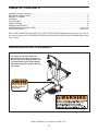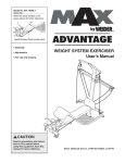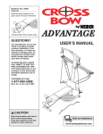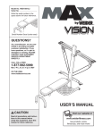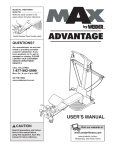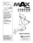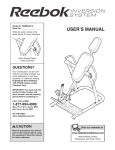
1
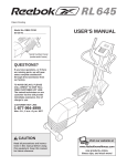
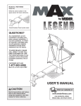
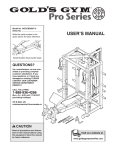
Model No. 15396.2
Serial No.
Visit our website at
www.proform.com
Write the serial number
in products,
the
new
prizes,
space above for future
reference.
fitness tips, and much more!
Visit our website at
www.weslo.com
new products, prizes,
fitness tips, and much more!
ADVANTAGE
Visit our website at
Serial Number Decal
(under seat)
www.healthrider.com
new products, prizes,
As a manufacturer,
we are
comfitness
tips,
and much more!
mitted to providing complete
customer satisfaction. If you
have questions, or if a part is
damaged or missing, PLEASE
CONTACT OUR CUSTOMER
SERVICE DEPARTMENT
Visit our website at
DIRECTLY.
CALL TOLL-FREE:
www.nordictrack.com
1-877-992-5999
new products, prizes,
Mon.–Fri., 6 a.m.–6
p.m.tips,
MSTand much more!
fitness
ON THE WEB:
www.weiderservice.com
Visit our website at
www.weiderfitness.com
new products, prizes,
fitness tips, and much more!
Visit our website at
www.freemotionfitness.com
CAUTION
Read all precautions and instrucVisit our
tions in this manual before
using this equipment. Save this
manual for future reference.
website at
www.weiderplatinum.com
Visit our website at
www.jumpking.com
new products, prizes,
fitness tips, and much more!
USER’S MANUAL
Visit our website at
www.imagefitness.com
new products, prizes,
fitness tips, and much more!
Visit our website at
www.reebokhomefitness.com
new products, prizes,
fitness tips, and much more!
Visit our website at
www.TheCrossBow.com
Visit our website at
www.weiderplatinum.com
TABLE OF CONTENTS
WARNING DECAL PLACEMENT . . . . . . . . . . . . . . . . . . . . . . . . . . . . . . . . . . . . . . . . . . . . . . . . . . . . . . . . . . . . . 2
IMPORTANT PRECAUTIONS . . . . . . . . . . . . . . . . . . . . . . . . . . . . . . . . . . . . . . . . . . . . . . . . . . . . . . . . . . . . . . . . 3
BEFORE YOU BEGIN . . . . . . . . . . . . . . . . . . . . . . . . . . . . . . . . . . . . . . . . . . . . . . . . . . . . . . . . . . . . . . . . . . . . . . 4
ASSEMBLY . . . . . . . . . . . . . . . . . . . . . . . . . . . . . . . . . . . . . . . . . . . . . . . . . . . . . . . . . . . . . . . . . . . . . . . . . . . . . . .5
ADJUSTMENTS . . . . . . . . . . . . . . . . . . . . . . . . . . . . . . . . . . . . . . . . . . . . . . . . . . . . . . . . . . . . . . . . . . . . . . . . . . 13
CABLE DIAGRAM . . . . . . . . . . . . . . . . . . . . . . . . . . . . . . . . . . . . . . . . . . . . . . . . . . . . . . . . . . . . . . . . . . . . . . . . .16
EXERCISE GUIDELINES . . . . . . . . . . . . . . . . . . . . . . . . . . . . . . . . . . . . . . . . . . . . . . . . . . . . . . . . . . . . . . . . . . 17
ORDERING REPLACEMENT PARTS . . . . . . . . . . . . . . . . . . . . . . . . . . . . . . . . . . . . . . . . . . . . . . . . . .Back Cover
LIMITED WARRANTY . . . . . . . . . . . . . . . . . . . . . . . . . . . . . . . . . . . . . . . . . . . . . . . . . . . . . . . . . . . . . . Back Cover
Note: A PART IDENTIFICATION CHART and a PART LIST/EXPLODED DRAWING are attached in the center of
this manual. Remove the PART IDENTIFICATION CHART and PART LIST/EXPLODED DRAWING before beginning assembly.
WARNING DECAL PLACEMENT
The decals shown here have been
placed on the resistance system. If a
decal is missing or illegible, please call
1-877-992-5999 to order a free replacement decal. Apply the decal in the location shown.
Keep hands and
fingers clear of
this area.
MAX by WEIDER is a trademark of ICON IP, Inc.
2
IMPORTANT PRECAUTIONS
WARNING:
To reduce the risk of serious injury, read the following important precautions
before using the resistance system.
1. Read all instructions in this manual and all
warnings on the resistance system before
using the resistance system. Use the resistance system only as described in this manual.
12. Make sure the storage knob is in place and
fully tightened each time the resistance system is used.
13. When adding resistance, both ends of the
resistance bars must rest under the two “U”channels. Add and remove resistance bars
from the “U”-channels one resistance bar at
a time.
2. It is the responsibility of the owner to ensure
that all users of the resistance system are
adequately informed of all precautions.
3. The resistance system is intended for home
use only. Do not use the resistance system in
any commercial, rental, or institutional setting.
14. Keep clear of the area around the “U”-channels while the resistance system is in use.
Do not add or remove resistance bars from
the “U”-channels while the end of the long
cable is pulled out.
4. Keep the resistance system indoors, away
from moisture and dust. Place the resistance
system on a level surface, with a mat
beneath it to protect the floor or carpet. Make
sure that there is enough clearance around
the resistance system to mount, dismount,
and use the resistance system.
15. Always adjust the resistance bar assembly to
the horizontal position and make sure the
fulcrum knob is secure before using the
resistance system.
16. Make sure the rings on the resistance bars
are pushed against the tray before using the
resistance system.
5. Inspect and properly tighten all parts regularly. Replace any worn parts immediately.
6. Keep children under 12 and pets away from
the resistance system at all times.
17. Always disconnect the lat bar from the short
cables when performing an exercise that
does not require it.
7. Keep hands and feet away from moving parts.
18. The resistance system is designed to be
used with the included resistance, and the
resistance included with a MAX by WEIDER
MAX PACK. Do not use the resistance system with any other type of resistance.
8. Always wear athletic shoes for foot protection while exercising.
9. The top frame is not designed to be used for
pull-up exercises. Do not hang on the top
frame.
19. Make sure that the cables remain on the pulleys at all times. If the cables bind as you are
exercising, stop immediately and make sure
that the cables are on the pulleys. Replace all
cables at least every two years.
10. The resistance system is designed to support a maximum user weight of 300 pounds.
11. Pull on the low pulley cable only while sitting
on the bench or standing on the base plate.
Pull on the high pulley cables only while sitting on the bench, with the seat in one of the
three positions closest to the upright base,
or while standing on the base plate.
20. If you feel pain or dizziness while exercising,
stop immediately and begin cooling down.
WARNING:
Before beginning this or any exercise program, consult your physician. This
is especially important for persons over the age of 35 or persons with pre-existing health problems.
Read all instructions before using. ICON assumes no responsibility for personal injury or property
damage sustained by or through the use of this product.
3
BEFORE YOU BEGIN
Thank you for selecting the innovative MAX by
WEIDER™ ADVANTAGE resistance system. The resistance system offers a selection of stations designed to
develop every major muscle group of the body. Whether
your goal is to tone your body, build dramatic muscle
size and strength, or improve your cardiovascular system, the resistance system will help you to achieve the
specific results you want.
Service Department toll-free at 1-877-992-5999,
Monday through Friday, 6 a.m. until 6 p.m. Mountain
Time (excluding holidays). To help us assist you, please
note the product model number and serial number
before calling. The model number is 15396.2. The serial
number can be found on a decal attached to the resistance system (see the front cover of this manual for the
location of the decal).
For your benefit, read this manual carefully before
using the resistance system. If you have questions
after reading this manual, please call our Customer
Before reading further, please review the drawing below
and familiarize yourself with the parts that are labeled.
ASSEMBLED DIMENSIONS:
Height: 82 in. / 208 cm
Width: 66 in. / 168 cm
Depth: 80 in. / 203 cm
Top Frame
Lat Tower
High Pulley
Fulcrum Knob
Resistance Bars
Upright
“U”-Channel
Storage Knob
Foot Plate
Backrest
Low Pulley
Seat Knob
Base Plate
Seat
Leg Lever
Lat Bar
4
ASSEMBLY
• Tighten all parts as you assemble them, unless
instructed to do otherwise.
Make Things Easier for Yourself
This manual is designed to ensure that the resistance system can be assembled successfully by
most people. However, it is important to realize
that the versatile resistance system has many
parts and that the assembly process will take
time. Most people find that by setting aside plenty
of time, assembly will go smoothly.
• As you assemble the resistance system, make
sure all parts are oriented as shown in the drawings.
The included Allen wrenches
and the following tools (not included) are required for assembly:
• Two adjustable wrenches
Before beginning assembly, carefully read the
following information and instructions:
• One rubber mallet
• Assembly requires two persons.
• One standard screwdriver
• Place all parts in a cleared area and remove the
packing materials. Do not dispose of the packing
materials until assembly is completed.
• One Phillips screwdriver
• Lubricant, such as grease or petroleum jelly,
and soapy water.
• For help identifying small parts, use the PART
IDENTIFICATION CHART. Note: Some small
parts may have been pre-attached for shipping. If
a part is not in the parts bag, check to see if it
has been pre-attached.
1.
Assembly will be more convenient if you have a
socket set, a set of open-end or closed-end
wrenches, or a set of ratchet wrenches.
1
Before beginning assembly, make sure that
you have read and understand the information in the box above.
3
Press two 2” Square Inner Caps (98) into the
Base (1).
Attach two Plastic Feet (53) and two Large Plastic
Feet (102) to the Base (1) with four #8 x 3/4” Tec
Screws (60).
Attach the Upright (3) to the Base (1) with two
3/8” x 2 3/4” Carriage Bolts (83), two 3/8” x 2 3/4”
Bolts (64), and four 3/8” Nylon Locknuts (76) as
shown. Note: This step will be easier to complete if the Upright and Base are tipped on
their sides.
76
53
60
5
53
64
76
1
98
76
102
60
83
98
102
60
2. Attach a Wheel (31) to the outside of the Base (1)
with a 3/8” x 4 1/4” Bolt (81), three 3/8” Washers
(75), and a 3/8” Nylon Locknut (76). Do not overtighten the Locknut; the Wheel must be able
to turn easily.
2
76
Attach the other Wheel (not shown) in the
same manner.
3. Press a 1 1/2” x 2 1/2” Inner Cap (41) into each
end of the Cross Tube (11).
3
23
41
Welded
Tube
5
105
46
5. See the inset drawing. Snap the Seat Knob (45)
into the Seat Carriage (12) and attach it with two
M6 x 16mm Screws (82) and two M6 Black Nylon
Locknuts (69). Make sure the slot in the Knob
is aligned with the slot in the Seat Carriage.
Holes
52
52
27
Orient the Front Leg (6) as shown. Attach the
Front Leg to the Bench Rail (5) with the Rail
Bracket (105), four 5/16” x 1” Button Screws (46),
and four 5/16” Split Washers (52).
46
27
6
5
13
Round
End
Orient the Seat (13) and the Seat Backing (9) as
shown. Attach the Seat and the Seat Backing to
the Seat Carriage (12) with four M6 x 16mm
Screws (82).
9
12
12
82
6
41
11
4
Orient the Bench Rail (5) as shown. Slide the Rail
Bracket (105) into the indicated end of the Bench
Rail, and align the holes in the Bracket with the
holes in the Bench Rail.
81
47
75
73
4. Press two 2 1/4” Round Outer Caps (27) onto the
ends of the Front Leg (6).
75
31
1
3
Orient the Cross Tube (11) as shown, with the
welded tubes at the bottom. Attach the Foot Plate
(23) and the Cross Tube to the Upright (3) with
two 3/8” x 5 1/2” Carriage Bolts (73), two 3/8”
Washers (75), and two 3/8” Nuts (47). Do not
insert a bolt into the top hole in the Foot Plate
yet.
75
Slot
82
82
45
69
6. Pull the Seat Knob (45, not shown) out as far as
it will go, and slide the Seat Carriage (12) onto
the Bench Rail (5). Engage the Seat Knob into
the third hole from the end of the Bench Rail.
6
Third
Hole
45
See the inset drawing. Thread the Hook (104)
into the bottom of the Bench Rail (5). Do not
overtighten the Hook, or the Bench Rail will
be difficult to assemble in step 7.
99
5
62
Wide
End
Press the two Rail Inner Caps (99), with the wide
ends on the top or bottom (as indicated), into the
ends of the Bench Rail (5). Attach the Caps with
four #8 x 3/4” Screws (62).
6
76
Locate the Leg Lever Cable (32), which has three
ends connected in the middle with a bracket.
Route the end of the Cable with the eyebolt under
a “V”-pulley (92). Attach the “V”-pulley to the
Front Leg (6) with a 3/8” x 4 1/4” Bolt (81) and a
3/8” Nylon Locknut (76). Slide the other two
ends of the Cable onto the Hook (104).
62
92
12
32
81
Eyebolt
62
5
Wide
End
99
104
7
7. Attach the Bench Rail (5) to the Upright (3) with a
3/8” x 5 1/2” Bolt (66), a 3/4” Spacer (17), a 7/8”
Spacer (106), and a 3/8” Nylon Locknut (76).
Fully tighten the Storage Knob (30) into the
Upright and the Bench Rail.
30
5
8. Attach the Lat Tower (4) to the Upright (3) with
four 3/8” x 1” Button Screws (87) and four 3/8”
Split Washers (103).
17
76
3
66
106
8
Attach the Name Plate (89) to the Lat Tower (4)
with two #8 x 3/4” Screws (62).
4
62
87
89
62
3
7
103
87
62
9. Press two 1 1/2” Round Inner Caps (38) into the
ends of the Top Frame (10).
9
70
65
Attach two Eyebolts (34) to the Top Frame (10)
with two 5/16” Washers (59) and two 5/16” Nylon
Locknuts (65). Do not overtighten the Locknuts;
the Eyebolts must be able to rotate freely.
59
38
Attach the Top Frame (10) to the Lat Tower (4)
with two 3/8” x 3” Button Screws (70), two 3/8”
Washers (75), and the Top Frame Cover (93).
Make sure that the Eyebolts (34) are oriented
as shown in the inset drawing. If they are not,
turn the Top Frame around and reattach it.
10
10. Attach the two 10-pound Short Caps (20) to the
10-pound Center Resistance Bar (44) with two
M4 x 12mm Flat Head Screws (85).
10
75
93
34
Side View
4
36
72
4
18
85
85
11
Rings on
this side
96
95
101
20
85
8
4
34
44
Attach the Cover Plate (72), with the edges up, to
the Tray (35) with two 5/16” x 3/4” Button Screws
(86).
38
34
67
Set the resistance bars into the Tray (35) in the
following order: the 10-pound Removable
Resistance Bar (67), the 20-pound Removable
Resistance Bar (36), an 80-pound Resistance Bar
(95), the 10-pound Center Resistance Bar (44), an
80-pound Resistance Bar (95), and the 40-pound
Resistance Bar (96). Make sure the indicated
rings are on the side shown and the arrows
point toward the Tray.
65
59
Using ten M4 x 12mm Flat Head Screws (85),
attach the two 10-pound Caps (101) to the 10pound Removable Resistance Bar (67), the two
20-pound Caps (88) to the 20-pound Removable
Resistance Bar (36), the four 80-pound Caps
(100) to the two 80-pound Resistance Bars (95),
and the two 40-pound Caps (79) to the 40-pound
Resistance Bar (96).
11. Locate the Fulcrum (18) on the Lat Tower (4) (see
the inset drawing). Slide the Tray (35) onto the
rods on the Fulcrum. Make sure the Tray is oriented as shown in the drawing.
10
86
79
85
85
100
88
Edges
up
96
44
35
18
Rods
67
95
95
36
12. Press two 1” Square Inner Caps (54) into the indicated end of the Backrest Frame (15).
12
Attach a Plastic Foot (53) to the Backrest Frame
(15) with a #8 x 3/4” Screw (62).
14
Orient the Backrest (14) and the Backrest
Backing (8) as shown. Attach the Backrest and
the Backrest Backing to the Backrest Frame (15)
with four M6 x 45mm Screws (58).
8
53
15
58
54
13. Insert the rod on the Backrest Frame (15) into the
slot in the Seat Carriage (12). Hold the Backrest
Frame vertically over the Seat Carriage and
slide the rod into the slot, as shown in the
inset drawing.
62
58
13
Rod
15
15
Rod
Slot
12
14. Press two 2” Round Inner Caps (57) into the top
and bottom of the Leg Developer (19). Press two
1 3/4” Round Inner Caps (56) into the top and
bottom of the Leg Lever (7).
12
14
Lubricate a 3/8” x 2 3/4” Bolt (64) with grease.
Attach the Leg Lever (7) to the Leg Developer
(19) with the Bolt and a 3/8” Nylon Locknut (76).
Do not overtighten the Locknut; the Leg Lever
must be able to pivot easily.
78
56
Tube
26
Slide two Foam Pads (26) onto the tubes on the
Leg Lever (7). Press two 1 1/4” Round Inner
Caps (78) into the tubes. Repeat with the tube
on the Leg Developer (19).
56
9
Tube 57
76
7
19
64
Lubricate
57
78
15. Slide the Leg Developer (19) into the Bench Rail
(5). Align the hole in the Leg Developer with a
hole in the Front Leg (6). Tighten the Bench Knob
(42) into the hole in the Leg Developer.
15
7
Connect the eyebolt on the Leg Lever Cable (32)
to the indicated side of the Leg Lever (7) with a
5/16” Nylon Locknut (65).
19
65
Eyebolt
5
6
16. Locate the Long Cable (80). Insert one end of
the Cable through the welded tube on the indicated end of the Cross Tube (11) and then through a
Swivel Arm (22). If necessary, use the tip of a
screwdriver to pull the end of the Cable out of the
Swivel Arm. Make sure the Cable is on the indicated side of the welded rod in the Swivel Arm.
32
42
16
80
11
Insert the Swivel Arm (22) into the welded tube
on the Cross Tube (11). Secure the Swivel Arm
with a #8 x 3/8” Screw (107).
71
107
22
28
76
Wrap the Long Cable (80) around a 90mm Pulley
(28). Attach the Pulley inside of the Swivel Arm
(22) with a 3/8” x 1 1/2” Button Bolt (71) and a
3/8” Nylon Locknut (76).
17. Wrap the Long Cable (80) around a 90mm Pulley
(28). Attach the Pulley and a Pulley Guard (29) to
the indicated 3/8” x 5 1/2” Carriage Bolt (73) with
a 3/8” Nylon Locknut (76). Make sure the flat
edge of the Pulley Guard is on the side shown.
17
18. Attach a Pulley Housing (94) to the indicated “U”channel on the 10-pound Center Resistance Bar
(44) with a 3/8” x 4” Button Bolt (24), two Pivot
Bushings (74), and a 3/8” Nylon Locknut (76).
18
Flat
Edge
29 76
80
73
Wrap the Long Cable (80) around a 90mm Pulley
(28). Attach the Pulley inside of the Pulley
Housing (94) with a 3/8” x 1 1/2” Button Bolt (71)
and a 3/8” Nylon Locknut (76).
28
44
74
76
“U”-Channel
71
28
10
Rod
80
74
94
24
76
19. Wrap the Long Cable (80) under a 90mm Pulley
(28) as shown. Attach the Pulley and a Pulley
Guard (29) to the Upright (3) with a 3/8” x 4 1/2”
Button Bolt (40) and a 3/8” Nylon Locknut (76).
Make sure the flat edge of the Pulley Guard is
on the bottom.
19
40
3
28
29
76
Flat
Edge
20. Attach a Pulley Housing (94) to the indicated “U”channel on the 10-pound Center Resistance Bar
(44) with a 3/8” x 4” Button Bolt (24), two Pivot
Bushings (74), and a 3/8” Nylon Locknut (76).
20
44
Wrap the Long Cable (80) around a 90mm Pulley
(28). Attach the Pulley inside of the Pulley
Housing (94) with a 3/8” x 1 1/2” Button Bolt (71)
and a 3/8 Nylon Locknut (76).
74
74
94
24
76
71
28
80
21. Wrap the Long Cable (80) around a 90mm Pulley
(28). Attach the Pulley and a Pulley Guard (29) to
the indicated 3/8” x 5 1/2” Carriage Bolt (73) with
a 3/8” Nylon Locknut (76). Make sure the flat
edge of the Pulley Guard is on the side
shown.
21
80
22. Make sure there are no resistance bars under the
“U”-channels on the 10-pound Center Resistance
Bar (not shown). Have a second person pull on
the Long Cable (80) to create slack in the Cable.
29
Flat
Edge
76
73
22
Insert the end of the Long Cable (80) through the
welded tube on the indicated end of the Cross
Tube (11) and then through the remaining Swivel
Arm (22). Make sure the Cable is on the indicated side of the welded rod in the Swivel Arm.
80
Insert the Swivel Arm (22) into the welded tube
on the Cross Tube (11). Secure the Swivel Arm
with a #8 x 3/8” Screw (107).
Wrap the Long Cable (80) around a 90mm Pulley
(28). Attach the Pulley inside of the Swivel Arm
(22) with a 3/8” x 1 1/2” Button Bolt (71) and a
3/8” Nylon Locknut (76).
28
11
Rod
28
22
76
71
107
11
76
80
23. Locate the two Short Cables (33). Wrap one of
the Cables around a 90mm Pulley (28). Attach
the Pulley to a High Pulley Housing (21) with a
3/8” x 1 1/2” Button Bolt (71) and a 3/8” Nylon
Locknut (76).
23
Repeat this step with the other Short Cable
(33).
76
21
28
71
33
24. Make sure that all parts have been properly tightened. The use of the remaining parts will be explained in
ADJUSTMENTS, beginning on the following page.
Before using the resistance system, pull the long cable a few times to be sure that it moves smoothly over
the pulleys. If the cable does not move smoothly, find and correct the problem. IMPORTANT: If the cables
are not properly installed, they may be damaged when heavy resistance is used. See the CABLE
DIAGRAM on page 16 for proper cable routing.
12
ADJUSTMENTS
This section explains how to adjust the resistance system. See the EXERCISE GUIDELINES on page 17 for
important information about how to get the most benefit from your exercise program. Also, refer to the accompanying exercise guide to see the correct form for each exercise.
Make sure all parts are properly tightened each time the resistance system is used. Replace worn parts immediately. The resistance system can be cleaned with a damp cloth and a mild, non-abrasive detergent. Do not use
solvents. The resistance bars can be cleaned with a vinyl and rubber protectant, available at an automotive or
department store.
ATTACHING THE HIGH PULLEYS AND LEG LEVER
To use a high pulley, slide the hook on the High
Pulley Housing (21) onto an Eyebolt (34). Attach the
end of the Short Cable (33) without the ball to the end
of the Long Cable (80) with a Cable Clip (51). Attach
the other high pulley in the same manner.
Ball
To use the Leg Lever (not shown), attach the two
ends of the Leg Lever Cable (32) to the ends of the
Long Cable (80) with two Cable Clips (51).
34
21
33
Remove the high pulleys, and detach the Leg Lever
Cable (32), when not in use. Store the ends of the
Leg Lever Cable on the Hook (104) under the Bench
Rail (not shown).
80
32
51
104
ADJUSTING THE SEAT
The Seat (13) can be secured in any of five positions
on the Bench Rail (5). To move the Seat, pull the
Seat Knob (45) out as far as it will go, and slide the
Seat to the desired position. Engage the Seat Knob
into an adjustment hole in the Bench Rail.
14
13
To perform row exercises, the leg press strap must be
attached to the long cable (see ATTACHING THE
ACCESSORIES, on page 14), and the Seat Carriage
(12) must be able to roll along the Bench Rail (5).
First, remove the Backrest (14) from the Seat
Carriage (see ADJUSTING THE BACKREST on page
15). Then, pull the Seat Knob (45) out as far as it will
go, and turn the Knob so that the pin rests at the end
of the “L”-shaped slot (see the inset drawing).
5
12
Pin
12
13
51
45 “L”-Slot
ATTACHING THE ACCESSORIES
33
To attach a Short Handle (49) to a high pulley, first
attach the high pulley to the resistance system (see
ATTACHING THE HIGH PULLEYS AND LEG LEVER
on page 13). Then, attach the Short Handle to the
Short Cable (33) with a Cable Clip (51).
51
49
The Long Handles (not shown) and the Ankle Strap
(not shown) can be attached to the Long Cable (80)
with Cable Clips (51). Attach the Leg Press Strap (not
shown) to both ends of the Long Cable, or the Lat Bar
(not shown) to the Short Cables (33), with two Cable
Clips.
80
ADJUSTING THE RESISTANCE
To add resistance, hold a “U”-channel on the 10pound Center Resistance Bar (44) firmly and push
the end of a resistance bar under it. Repeat with the
other end of the resistance bar. If more resistance is
needed, add one resistance bar at a time.
“U”-Channel
Note: When adding resistance, always start with the
heaviest resistance bar to be used, and finish with the
lightest resistance bar. When removing resistance
bars from the “U”-channels, start with the lightest
resistance bar and finish with the heaviest.
35
67
36
WARNING:
When adding resistance, make sure that both ends of the resistance bar rest under the two “U”-channels. The
rings on the Removable Resistance Bars (36,
67) must be pushed against the Tray (35). Do
not add or remove resistance bars from the
“U”-channels while an end of the Long Cable
(80) is pulled out.
44
Resistance
Bars
“U”-Channel
80
Note: The resistance system uses progressive resistance. As the resistance bars begin to bend, the
amount of resistance will increase gradually. As the
resistance bars bend further, the resistance will
increase rapidly.
Additional resistance can be added to the resistance
system. To purchase more resistance, please call the
toll-free number on the front cover of this manual and
ask for model number WEMC0642 (100-Pound MAX
PACK) or WEMC0942 (200-Pound MAX PACK).
14
ADJUSTING THE BACKREST
Rod
The Backrest (14) can be used in a level position or
one of three inclined positions. To use the Backrest in a
level position, secure the Seat Carriage (12) at the hole
in the Bench Rail (5) closest to the Leg Developer (19)
(see ADJUSTING THE SEAT on page 13).
15
Slot
12
13
To use the Backrest (14) in an inclined position,
secure the Seat Frame (12) at one of the three
adjustment holes on the Upright (3) side of the Bench
Rail (5). Rest the Backrest against the Upright (3).
For row exercises and for using the Leg Lever (7),
remove the Backrest (14) from the Seat Carriage
(12). Hold the Backrest vertically over the Seat (13)
and lift the rod out of the slot in the Seat Carriage
(see the inset drawing). To use the Leg Lever (7),
secure the Seat Carriage (12) at the second hole
from the Leg Developer.
3
14
19
7
12
5
STORING THE RESISTANCE SYSTEM
To store the resistance system, slide the ends of the
Leg Lever Cable (32) onto the Hook (104). Make sure
the Seat (13) is in the position closest to the Front
Leg (6) (see ADJUSTING THE SEAT on page 13).
Next, remove the Storage Knob (30) from the Upright
(3). Lift the Front Leg toward the Top Frame (10), and
tighten the Storage Knob into the side of the Upright
and the Bench Rail. Remove all of the resistance
bars from the “U”-channels on the 10-pound Center
Resistance Bar (44) (see ADJUSTING THE
RESISTANCE on page 14). Finally, loosen the
Fulcrum Knob (43) and pull it out as far as it will go.
Turn the resistance bar assembly vertically and
engage the Fulcrum Knob into the fulcrum on the Lat
Tower (4). Note: Storing the resistance bars vertically will prolong the life of the resistance bars.
Resistance
Bars
“U”-Channel
“U”-Channel
44
3
6
13
104
15
31
Stored Position
Hold in
this area
Make sure that all of
the resistance bars are removed from the “U”channels before moving the resistance bar
assembly to the stored position.
80
1
32
WARNING:
43
30
7
To move the resistance system, place the toe of your
shoe on the end of the Base (1) and hold the resistance system in the indicated area. Tilt the resistance
system back onto the Wheels (31) and roll it to the
new location. Be careful not to let the Front Leg (6)
or Leg Lever (7) pinch your hands when you tilt
the system back.
Make sure that the resistance bar assembly is
in the horizontal position and that the Storage
Knob (30) is in place and fully tightened each
time the resistance system is used.
10
USING THE REMOVABLE RESISTANCE BARS
The Removable Resistance Bars (36, 67) can be used
to exercise apart from the resistance system, as shown
in the video or on the exercise guide. To remove a
Resistance Bar, pull it out of the Tray (35).
67 36
To replace the Removable Resistance Bars (36, 67),
slide them into the Tray (35) from the side shown, so
that the arrows on the rings point toward the Tray.
Make sure the rings are pushed against the Tray.
35
Rings
ADJUSTING THE LEG DEVELOPER
To adjust the height of the Leg Developer (19),
remove the Bench Knob (42) from the Front Leg (6).
Align the hole in the Leg Developer with one of the
holes in the Front Leg. Retighten the Knob into the
Front Leg and Leg Developer.
19
5
42
6
CABLE DIAGRAM
The cable diagram shows the proper routing of the
Long Cable (80). Use the diagram to make sure that
the cable has been assembled correctly. If the cable
has not been correctly routed, the resistance system
will not function properly and damage may occur. The
numbers show the correct route for the cable.
Long Cable (80)
5
7
6
4
2
16
3
1
EXERCISE GUIDELINES
THE FOUR BASIC TYPES OF WORKOUTS
PERSONALIZING YOUR EXERCISE PROGRAM
Muscle Building
To increase the size and strength of your muscles,
push them close to their maximum capacity. Your muscles will continually adapt and grow as you progressively increase the intensity of your exercise. You can
adjust the intensity level of an individual exercise in
two ways:
• by changing the amount of resistance used
• by changing the number of repetitions or sets performed. (A “repetition” is one complete cycle of an
exercise, such as one sit-up. A “set” is a series of
repetitions.)
Determining the exact length of time for each workout,
as well as the number of repetitions or sets completed,
is an individual matter. It is important to avoid overdoing it during the first few months of your exercise program. You should progress at your own pace and be
sensitive to your body’s signals. If you experience pain
or dizziness at any time while exercising, stop immediately and begin cooling down. Find out what is wrong
before continuing. Remember that adequate rest and a
proper diet are important factors in any exercise program.
WARMING UP
The proper amount of resistance for each exercise
depends upon the individual user. You must gauge
your limits and select the amount of resistance that is
right for you. Begin with 3 sets of 8 repetitions for each
exercise you perform. Rest for 3 minutes after each
set. When you can complete 3 sets of 12 repetitions
without difficulty, increase the amount of resistance.
Begin each workout with 5 to 10 minutes of stretching
and light exercise to warm up. Warming up prepares
your body for more strenuous exercise by increasing
circulation, raising your body temperature and delivering more oxygen to your muscles.
WORKING OUT
Toning
You can tone your muscles by pushing them to a moderate percentage of their capacity. Select a moderate
amount of resistance and increase the number of repetitions in each set. Complete as many sets of 15 to
20 repetitions as possible without discomfort. Rest for
1 minute after each set. Work your muscles by completing more sets rather than by using high amounts of
resistance.
Each workout should include 6 to 10 different exercises. Select exercises for every major muscle group,
emphasizing areas that you want to develop most. To
give balance and variety to your workouts, vary the
exercises from session to session.
Schedule your workouts for the time of day when your
energy level is the highest. Each workout should be
followed by at least one day of rest. Once you find the
schedule that is right for you, stick with it.
Weight Loss
To lose weight, use a low amount of resistance and
increase the number of repetitions in each set.
Exercise for 20 to 30 minutes, resting for a maximum
of 30 seconds between sets.
EXERCISE FORM
Cross Training
Cross training is an efficient way to get a complete and
well-balanced fitness program. An example of a balanced program is:
• Plan strength training workouts on Monday,
Wednesday, and Friday.
• Plan 20 to 30 minutes of aerobic exercise, such as
running on a treadmill or riding on an elliptical or
exercise cycle, on Tuesday and Thursday.
• Rest from both strength training and aerobic exercise
for at least one full day each week to give your body
time to regenerate.
The combination of strength training and aerobic exercise will reshape and strengthen your body, plus develop your heart and lungs.
Maintaining proper form is an essential part of an
effective exercise program. This requires moving
through the full range of motion for each exercise, and
moving only the appropriate parts of the body.
Exercising in an uncontrolled manner will leave you
feeling exhausted. On the exercise guide accompanying this manual you will find photographs showing the
correct form for several exercises, and a list of the
muscles affected. Refer to the muscle chart on page
18 to find the names of the muscles.
The repetitions in each set should be performed
smoothly and without pausing. The exertion stage of
each repetition should last about half as long as the
return stage. Proper breathing is important. Exhale
during the exertion stage of each repetition and inhale
during the return stroke. Never hold your breath.
17
slowly as you stretch and do not bounce. Ease into
each stretch gradually and go only as far as you can
without strain. Stretching at the end of each workout
is an effective way to increase flexibility.
Rest for a short period of time after each set. The
ideal resting periods are:
• Rest for three minutes after each set for a muscle
building workout.
• Rest for one minute after each set for a toning workout.
• Rest for 30 seconds after each set for a weight loss
workout.
Plan to spend the first couple of weeks familiarizing
yourself with the equipment and learning the proper
form for each exercise.
STAYING MOTIVATED
For motivation, keep a record of each workout. The
chart on page 19 of this manual can be photocopied
and used to schedule and record your workouts. List
the date, the exercises performed, the resistance
used, and the numbers of sets and repetitions completed. Record your weight and key body measurements at the end of every month. Remember, the key
to achieving the greatest results is to make exercise a
regular and enjoyable part of your everyday life.
COOLING DOWN
End each workout with 5 to 10 minutes of stretching.
Include stretches for both your arms and legs. Move
N
A
O
B
P
C
Q
D
R
E
H
G
F
L
M
T
S
U
I
V
J
W
K
18
MUSCLE CHART
A.
B.
C.
D.
E.
F.
G.
H.
I.
J.
K.
L.
M.
N.
O.
P.
Q.
R.
S.
T.
U.
V.
W.
Sternomastoid (neck)
Pectoralis Major (chest)
Biceps (front of arm)
Obliques (waist)
Brachioradials (forearm)
Hip Flexors (upper thigh)
Abductor (outer thigh)
Quadriceps (front of thigh)
Sartorius (front of thigh)
Tibialis Anterior (front of calf)
Soleus (front of calf)
Rectus Abdominus (stomach)
Adductor (inner thigh)
Trapezius (upper back)
Rhomboideus (upper back)
Deltoid (shoulder)
Triceps (back of arm)
Latissimus Dorsi (mid back)
Spinae Erectors (lower back)
Gluteus Medius (hip)
Gluteus Maximus (buttocks)
Hamstring (back of leg)
Gastrocnemius (back of calf)
MONDAY
Date:
/
TUESDAY
Date:
/
/
/
/
/
WEDNESDAY
Date:
THURSDAY
Date:
/
/
/
/
FRIDAY
Date:
EXERCISE
RESISTANCE
SETS
REPS
RESISTANCE
SETS
REPS
RESISTANCE
SETS
REPS
AEROBIC EXERCISE
EXERCISE
AEROBIC EXERCISE
EXERCISE
Make photocopies of this page for scheduling and recording your workouts.
19
PART IDENTIFICATION CHART
Refer to the drawings below to identify small parts used in assembly. The number in parentheses below each
drawing is the key number of the part, from the PART LIST on the reverse side of this page. Important: Some
parts may have been pre-assembled for shipping purposes. If you cannot find a part in the parts bags,
check to see if it has been pre-assembled.
3/4” Spacer (17)
7/8” Spacer (106)
2 1/4” Round Outer Cap (27)
1” Square Inner Cap (54)
1 1/4” Round Inner Cap (78)
2” Square Inner Cap (54)
1 1/2” x 2 1/2” Inner Cap (41)
1 1/2” Round Inner Cap (38)
1 3/4” Round
Inner Cap (56)
2” Round Inner Cap (57)
5/16” x 1” Button Bolt (46)
#8 x 3/4” Tec Screw (60)
3/8” Nylon Locknut (76)
#8 x 3/4” Screw (62)
3/8” x 1” Button Bolt (87)
3/8” x 1 1/2” Button Bolt (71)
M6 x 45mm Screw (58)
M6 x 16mm Screw (82)
M4 x 12mm Flat
Head Screw (85)
#8 x 3/8” Screw (107)
3/8” Nut (47)
5/16” Nylon Locknut (65)
M6 Black Nylon
Locknut (69)
3/8” x 2 3/4” Bolt (64)
3/8” x 2 3/4” Carriage Bolt (83)
5/16” Washer (59)
3/8” Washer (75)
3/8” x 3” Button Screw (70)
3/8” x 4” Button Bolt (24)
3/8” x 4 1/4” Bolt (81)
3/8” x 4 1/2” Button Bolt (40)
3/8” x 5 1/2” Bolt (66)
3/8” x 5 1/2” Carriage Bolt (73)
3/8” Split Washer (103)
5/16” Split Washer (52)
PART LIST—Model No. 15396.2
Key No.
1
2
3
4
5
6
7
8
9
10
11
12
13
14
15
16
17
18
19
20
21
22
23
24
25
26
27
28
29
30
31
32
33
34
35
36
37
38
39
40
41
42
43
44
45
46
47
48
49
50
51
52
53
54
55
56
57
Qty.
1
1
1
1
1
1
1
1
1
1
1
1
1
1
1
1
1
1
1
2
2
2
1
2
4
4
2
9
3
1
2
1
2
2
1
1
2
2
1
1
2
1
1
1
1
4
2
1
2
1
4
4
3
2
1
2
2
Description
Base
Base Plate
Upright
Lat Tower
Bench Rail
Front Leg
Leg Lever
Backrest Backing
Seat Backing
Top Frame
Cross Tube
Seat Carriage
Seat
Backrest
Backrest Frame
Backrest Cap
3/4” Spacer
Fulcrum
Leg Developer
10-pound Short Cap
High Pulley Housing
Swivel Arm
Foot Plate
3/8” x 4” Button Bolt
Arm Bushing
Foam Pad
2 1/4” Round Outer Cap
90mm Pulley
Pulley Guard
Storage Knob
Wheel
Leg Lever Cable
Short Cable
Eyebolt
Tray
20-pound Removable Resistance
Bar
Fulcrum Bushing
1 1/2” Round Inner Cap
Bench Rail Bracket
3/8” x 4 1/2” Button Bolt
1 1/2” x 2 1/2” Inner Cap
Bench Knob
Fulcrum Knob
10-pound Center Resistance Bar
Seat Knob
5/16” x 1” Button Screw
3/8” Nut
Leg Press Strap
Short Handle
Ankle Strap
Cable Clip
5/16” Split Washer
Plastic Foot
1” Square Inner Cap
45mm Round Inner Bushing
1 3/4” Round Inner Cap
2” Round Inner Cap
Key No. Qty.
58
59
60
61
62
63
64
65
66
67
68
69
70
71
72
73
74
75
76
77
78
79
80
81
82
83
84
85
86
87
88
89
90
91
92
93
94
95
96
97
98
99
100
101
102
103
104
105
106
107
108
109
#
#
#
#
#
4
2
4
6
11
6
3
3
1
1
2
2
2
6
1
2
4
10
20
6
4
2
1
3
12
2
1
12
2
4
2
1
6
1
1
1
2
2
1
1
2
2
4
2
2
4
1
1
1
2
1
2
1
1
1
1
1
Description
R1005A
M6 x 45mm Screw
5/16” Washer
#8 x 3/4” Tec Screw
Seat Wheel
#8 x 3/4” Screw
M6 Zinc Nylon Locknut
3/8” x 2 3/4” Bolt
5/16” Nylon Locknut
3/8” x 5 1/2” Bolt
10-pound Removable Resistance
Bar
Long Handle
M6 Black Nylon Locknut
3/8” x 3” Button Screw
3/8” x 1 1/2” Button Bolt
Cover Plate
3/8” x 5 1/2” Carriage Bolt
Pivot Bushing
3/8” Washer
3/8” Nylon Locknut
M6 Shoulder Bolt
1 1/4” Round Inner Cap
40-pound Cap
Long Cable
3/8” x 4 1/4” Bolt
M6 x 16mm Screw
3/8” x 2 3/4” Carriage Bolt
Fulcrum Endcap
M4 x 12mm Flat Head Screw
5/16” x 3/4” Button Screw
3/8” x 1” Button Screw
20-pound Cap
Name Plate
11mm Spacer
Retainer Ring
“V”-pulley
Top Frame Cover
Pulley Housing
80-pound Resistance Bar
40-pound Resistance Bar
Storage Knob Bracket
2” Square Inner Cap
Rail Inner Cap
80-pound Cap
10-pound Cap
Large Plastic Foot
3/8” Split Washer
Hook
Rail Bracket
7/8” Spacer
#8 x 3/8” Screw
Lat Bar
Hand Grip
User’s Manual
Exercise Guide
Exercise Decal
Large Allen Wrench
Small Allen Wrench
Note: “#” indicates a non-illustrated part. Specifications are subject to change without notice. See the back cover
of the user’s manual for information about ordering replacement parts.
EXPLODED DRAWING—Model No. 15396.2
14
38
65
59
58 62
54
58
78
56 76
78 26
99
27
76
105
46
6
85
101
76
28
33
13
19
65
59
21
26
78
62
46
5
52 1
53
42 92
60
27
81
81
31
75
62
98
102
53
60
83
75
60
62
76
75
102
83 60
2
28
103
29
66
81
68
71
41
88
35
18
37
87
28
76
51
22
20
76
85
74
101
24
28
107
25
24
43
28
37 91
84
74 94 74
76
64
76
85
85
94
29 109
75
31
28
79
100
103 87
80 28
76
98
76
74
71
4
76
99
30 97
73
39
78 82 62
17
82 106
76
82 62
104
76
32
44
36
96
67
38
34
71
64
57
55
52
71
85
88
86
72
95
100
26
65
62
93
79
85
20
9
33
82
61
63
90
77
12
45
63
82
63
62
90
77
63
63
61
61
77 61
63
90
77
89 62
77
90
61
69
3
23
26
82
82
57
40
7
56
58
10 21
16
62
53
15
70
34
8
75
100
85
R1005A
76
71
29
76
28
49
108
109
48
11 25
75
47
50
75
41
80
28
25
71
107
76
22
ORDERING REPLACEMENT PARTS
To order replacement parts, see the front cover of this manual. To help us assist you, please be prepared to give
the following information:
• te MODEL NUMBER of the product (15396.2)
• the NAME of the product (MAX by WEIDER ADVANTAGE resistance system)
• the SERIAL NUMBER of the product (see the front cover of this manual)
• the KEY NUMBER and DESCRIPTION of the part(s) (see the PART LIST and EXPLODED DRAWING in the
center of this manual)
LIMITED WARRANTY
ICON Health & Fitness, Inc. (ICON), warrants this product to be free from defects in workmanship and
material, under normal use and service conditions. ICON warrants the resistance bars for the lifetime of
the product, and all other parts for five (5) years from the date of purchase. Labor is covered for one (1)
year. This warranty extends only to the original purchaser. ICON's obligation under this warranty is limited to replacing or repairing, at ICON's option, the product through one of its authorized service centers.
All repairs for which warranty claims are made must be pre-authorized by ICON. If the product is shipped
to a service center, freight charges to and from the service center will be the customer’s responsibility. For
in-home service, the customer will be responsible for a minimal trip charge. This warranty does not extend
to any product or damage to a product caused by or attributable to freight damage, abuse, misuse,
improper or abnormal usage or repairs not provided by an ICON authorized service center; products used
for commercial or rental purposes; or products used as store display models. No other warranty beyond
that specifically set forth above is authorized by ICON.
ICON is not responsible or liable for indirect, special or consequential damages arising out of or in connection with the use or performance of the product or damages with respect to any economic loss, loss
of property, loss of revenues or profits, loss of enjoyment or use, costs of removal or installation or other
consequential damages of whatsoever nature. Some states do not allow the exclusion or limitation of incidental or consequential damages. Accordingly, the above limitation may not apply to you.
The warranty extended hereunder is in lieu of any and all other warranties and any implied warranties of
merchantability or fitness for a particular purpose is limited in its scope and duration to the terms set forth
herein. Some states do not allow limitations on how long an implied warranty lasts. Accordingly, the above
limitation may not apply to you.
This warranty gives you specific legal rights. You may also have other rights which vary from state to state.
ICON HEALTH & FITNESS, INC., 1500 S. 1000 W., LOGAN, UT 84321-9813
Part No. 221088 R1104A
Printed in USA © 2004 ICON IP, Inc.